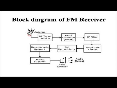
43 fm receiver block diagram
FM Receiver - ProjectFpga.com FM receiver Multiplier circuit Loop circuit NCO circuit FIR circuit The Design Reference. FM Receiver. Block diagram of first order loop filter . LIBRARY ieee; USE ieee.std_logic_1164.all; USE IEEE.numeric_std.ALL; ENTITY loop_filter IS-- Declarations port ... Design of All Digital FM Receiver Circuit - OpenCores The system of All Digital FM Receiver consists of a digital PLL cascaded with digital low pass filter. The block diagram of system is shown in Fig. 1. θ oθ ω i± ω o f ω± ω Fig. 1 Block diagram of All Digital FM Receiver circuit 2.1 Phase Detector Phase Detector (PD) detects phase error between input signal and output signal from NCO.
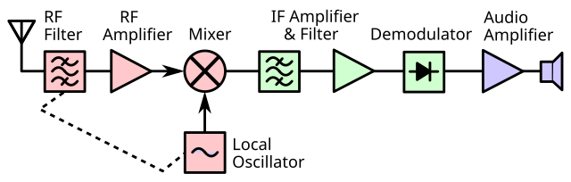
F.M. Receiver Tutorial - Block Diagrams - Electronics ... Block Diagrams F.M. Receiver Tutorial Most of these blocks are discussed individually, and in more detail, on other pages. See filters, mixers, frequency changers, am modulation and amplifiers. The f.m. band covers 88-108 MHz. There are signals from many radio transmitters in this band inducing signal voltages in the aerial.

Fm receiver block diagram
Principles of Communication - FM Radio - Tutorialspoint Let us take a look at the structure of FM transmitter and FM receiver along with their block diagrams and working. FM Transmitter. FM transmitter is the whole unit which takes the audio signal as an input and delivers FM modulated waves to the antenna as an output to be transmitted. FM transmitter consists of 6 main stages. Block Diagram of FM Receiver youtube - YouTube Introduction,functions of receiver and its block diagram PDF DSP and Digital Filters (2017-10178) FM Radio: 14 - 1 / 12 FM Radio Block Diagram 14: FM Radio Receiver •FM Radio Block Diagram •Aliased ADC •Channel Selection •Channel Selection (1) •Channel Selection (2) •Channel Selection (3) •FM Demodulator •Differentiation Filter •Pilot tone extraction + •Polyphase Pilot tone •Summary DSP and Digital Filters (2017-10178) FM Radio: 14 - 2 / 12 FM spectrum: 87.5 to 108MHz
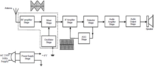
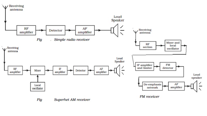
Fm receiver block diagram. Tuned Radio Frequency (TRF) Receiver Block Diagram ... The TRF receiver is the simplest type of AM radio receiver. The block diagram of a Tuned Radio Frequency (TRF) receiver is shown in the figure. Infinite number of transmitters installed throughout the world radiates radio waves in space. In general, these transmitters radiate different frequencies. FM Receiver Block diagram | Block diagram, Diagram ... Oct 4, 2019 - Hey, we are going to know about FM Receiver Block Diagram and Working Principle. Here, you will find the block diagram of FM Receiver which will help you to understand the working principle of FM Receiver. Superheterodyne FM Receiver - D&E Notes The block diagram of an FM receiver is illustrated in Figure (a). The RF amplifier amplifies the received signal intercepted by the antenna. The amplified signal is then applied to the mixer stage. The second input of the mixer comes from the local oscillator. The two input frequencies of the mixer generate an IF signal of 10.7 MHz. Block diagram of radio - BrainKart FM Transmitter Block diagram of an FM (frequency modulated) transmitter is given on Pic.2.4. Information being transferred, i.e. the modulating signal, is a signal from some LF source. it is being amplified in LF amplifier and then led into the HF oscillator, where the carrier signal is being created.
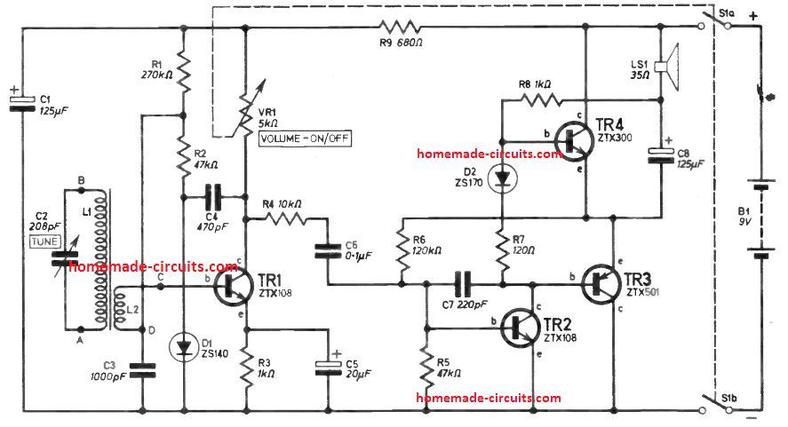
FM Receiver | Electronics Circuit with Full Explanation FM Receiver Circuit E xplanation. Here's a simple FM receiver with minimum components for local FM reception. Transistor BF495 (T2), together with a 10k resistor (R1), coil L, 22pF variable capacitor (VC), and internal capacitances of transistor BF494 (T1), comprises the Colpitts oscillator.. The resonance frequency of this oscillator is set by trimmer VC to the frequency of the transmitting ... Stereo FM Receiver - Mono Mode, Stereo Mode, Block Diagram ... Stereo FM Receiver Block Diagram The stereo section is more complicated. It uses three filters to extract (L + R) and (L – R) signals and the pilot-carrier from the discriminator output. The (L + R) signal is obtained from the low-pass filter, which contains frequencies between 50 Hz and 15 kHz. FM Receiver Block Diagram, Working Principle Understand ... Here you can see a simple block diagram of FM Receiver. FM Receiver Working Principle To easily understand the working principle of FM Receiver, see the block diagram. The first block is the Antenna. The antenna is used to receive the radio signals and intercepted it. The next block is Radio Frequency Amplifier or RF amplifier. FM Receiver Block Diagram - ELECTROPEDIA a. Mono FM Receiver Block Diagram b. Blok Diagram Penerima FM stereo Each Function Block a. Antenna: work to catch signals from the antenna bersal bermodulasi the transmitter. b. RF Amplifier: fatherly function strengthens the signal captured by the antenna before forwarded to block Mixer (mixer). c. OSC (Local Oscillator): mebangkitkan fatherly function of vibration…
Fm Transmitter Block Diagram And Explanation Of Each Block You can see in the block diagram of the FM Transmitter the first block. Information Source – Input Transducer – Transmitter – The Channel and The Noise – Receiver – Destination. This block diagram of a radio transmitter in a communication system is very simple and basic. FM broadcast the maximum modulating frequency is 15 kHz. FM Transmitter Block Diagram with Explanation ... Sreejith Hrishikesan May 13, 2021 FM Transmitter Block Diagram with Explanation of Each Block Block diagram of a low level FM broadcast transmitter is shown in figure. The master oscillator generates the RF signal (carrier) required for modulation. Master oscillator is generally a well defined LC oscillator. Fm Transmitter Block Diagram And Explanation Of Each Block ... Aug 24, 2021 · The block diagram of an FM receiver is illustrated in Figure a. AM Transmitter Block Diagram and explanation of each block. The low-level AM transmitter shown in the figure b is similar to a high-level transmitter except that the powers of the carrier and audio signals are not amplified. Superheterodyne FM receiver Block diagram and working ... Topics Covered:In this lecture I had explained the block diagram of Superheterodyne FM receiver and its working. The functions of two extra block which is re...
Double & Triple Conversion Superhet Radio Receiver ...
What is FM Receiver, How to build an Arduino FM Radio with ... Simplified FM receiver block diagram. To easily understand how an FM receiver work, let's explain a simplified FM receiver block diagram! 1. RF amplifier. The rf amplifier receives the desired signal from the antenna and provides tuning to remove the image signal alongside all unwanted signals on other frequencies. It then amplifies the ...
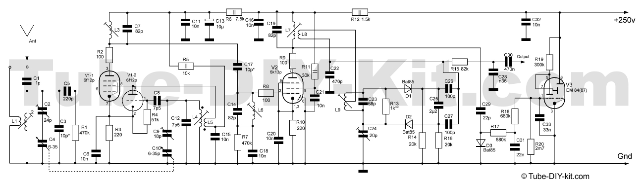
Radio-frequency unit FM superheterodyne receiver on 3 vacuum ...
Superheterodyne AM Receiver - Working with Block Diagram ... Superheterodyne AM Receiver - Working with Block Diagram and Schematics. A superheterodyne receiver uses signal mixing to convert the input radio signal into a steady intermediate frequency (IF) that can be worked with more easily than the original radio signal that has a different frequency, depending on the broadcasting station. The IF signal ...

Block Diagram of FM Receiver FM receiver comprises of RF ...
Superheterodyne Radio Receiver Block Diagram - Peter Vis Superheterodyne Radio Receiver Block Diagram. Here is a block diagram of a typical superheterodyne (superhet) radio receiver, together with theory and notes explaining each block. I have kept the theory very simple and at introductory level for beginners, however at some point there will be another article taking it further.

FM receivers with PLL
Fm receiver - SlideShare Telescopic Aerial It is an Antenna used in FM, AM and wireless phones to receive the signals. It convert the receiving signal in tiny Alternating Currents which are applied to receiver and the receiver extract the desired information. 13. Block Diagram. 14. Sections of Block Diagram of FM Receiver 15.

FM Receiver Block Diagram | ELECTROPEDIA
Simplified block diagram of an AM/FM radio with digital ... Fig. 1 shows a block diagram of an AM/FM radio receiver using digital audio signal processing. Depending on the continent, the FM input signal may be between 65-108 MHz. AM signals, including LW ...

File:Crystal radio receiver block diagram.svg - Wikimedia Commons
Draw the block diagram of an FM receiver and explain its ... Draw the block diagram of an FM receiver and explain its working. modulation; demodulation; class-12; Share It On Facebook Twitter Email. 1 Answer +1 vote . answered Mar 14, 2020 by Richa01 (53.5k points) selected Mar 15, 2020 by Mohit01 . Best answer. RF amplifier: ...

FM Receiver Block Diagram, Working Principle Understand ...
Radio Transmitter and Receiver | Working | Block Diagram ... A block diagram of a simple continuous wave (CW) transmitter is shown in Figure 6. The first block is the conventional crystal oscillator and then the final power amplifier. A power supply is provided for the oscillator and the final power amplifier. Figure 6. A block diagram representing various stages of a basic continuous wave radio transmitter.
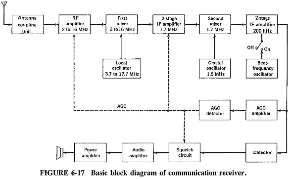
Communication Receiver Block Diagram | Extensions of ...
PDF Chapter 9: FM Receivers - N0GSG compared to an AM receiver are in blue. • Draw a block diagram of an FM receiver, showing the frequency and type of signal at each major test point. • Explain the operation and alignment of Foster-Seeley/Ratio, PLL, and quadrature FM detector circuits. • Describe the features of noise-suppressing circuits in an FM receiver.
Superheterodyne AM Receiver - Working with Block Diagram and ...
Block diagram of FM transmitter and receiver and its ... February 07, 2017 Block diagram of FM transmitter and receiver and its explanation FM transmitter Frequency Modulation is the process in which the frequency of the carrier signal is varied by the modulating signal while the amplitude remains constant Using Reactance modulator direct method The FM transmitter has three basic sections.
Fm receiver - How To Discuss
FM Radio Block Diagram - Peter Vis This superheterodyne FM radio block diagram shows all the main stages of a modern radio. The first three stages are very similar to an AM radio block diagram; however, the main difference is in the limiter and FM detector stages, which are crucial to FM reception.These stages are responsible for decoding the frequency-modulated signal.
Simple Radio Receiver Block Diagram
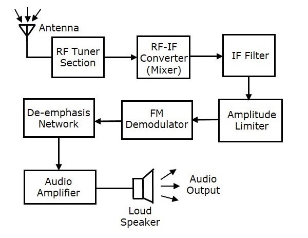
Analog Communication - Receivers - Tutorialspoint FM Receiver The block diagram of FM receiver is shown in the following figure. This block diagram of FM receiver is similar to the block diagram of AM receiver. The two blocks Amplitude limiter and De-emphasis network are included before and after FM demodulator. The operation of the remaining blocks is the same as that of AM receiver.

File:Block diagram of reflectional radio receiver (English ...
PDF DSP and Digital Filters (2017-10178) FM Radio: 14 - 1 / 12 FM Radio Block Diagram 14: FM Radio Receiver •FM Radio Block Diagram •Aliased ADC •Channel Selection •Channel Selection (1) •Channel Selection (2) •Channel Selection (3) •FM Demodulator •Differentiation Filter •Pilot tone extraction + •Polyphase Pilot tone •Summary DSP and Digital Filters (2017-10178) FM Radio: 14 - 2 / 12 FM spectrum: 87.5 to 108MHz

FM Radio Receiver
Block Diagram of FM Receiver youtube - YouTube Introduction,functions of receiver and its block diagram
Radio Transmitter and Receiver | Working | Block Diagram ...
Principles of Communication - FM Radio - Tutorialspoint Let us take a look at the structure of FM transmitter and FM receiver along with their block diagrams and working. FM Transmitter. FM transmitter is the whole unit which takes the audio signal as an input and delivers FM modulated waves to the antenna as an output to be transmitted. FM transmitter consists of 6 main stages.
reflex radio receivers

File:Superheterodyne receiver block diagram 2.svg - Wikipedia
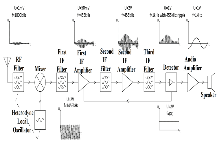
FM Receiver Block Diagram | Intermediate Frequency and IF ...

Block Diagram of superheterodyne radio receiver ...
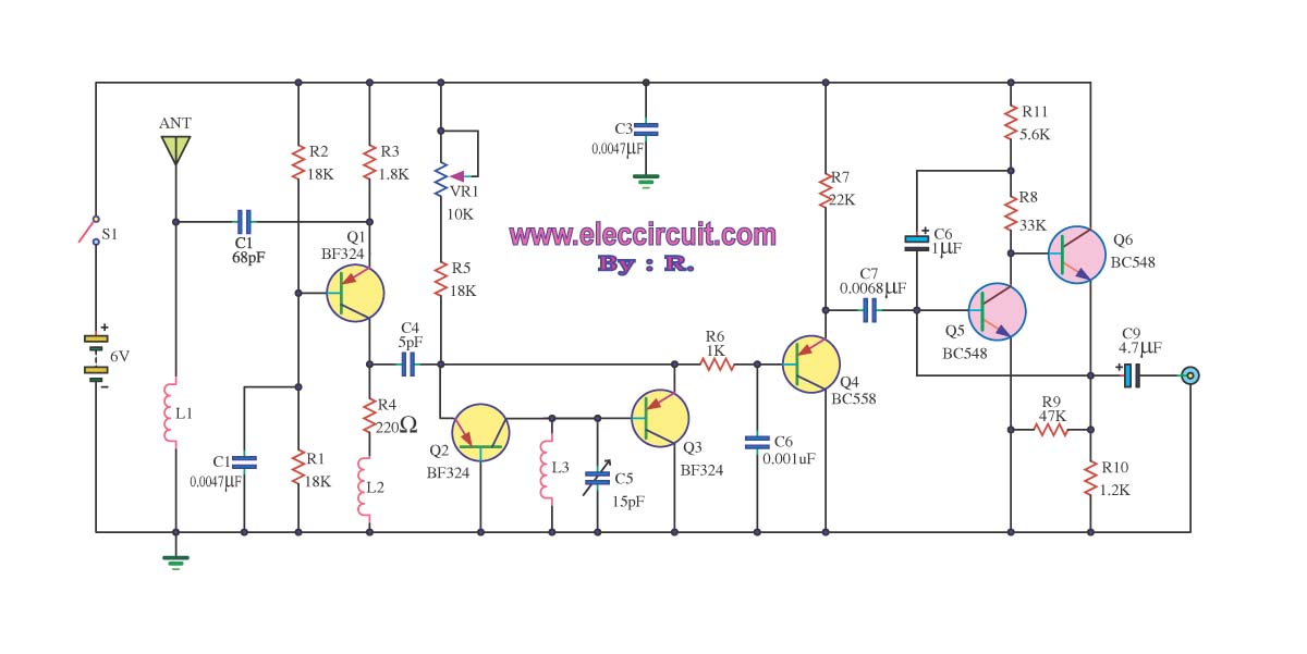
FM receiver circuit with PCB - Simple circuit - Eleccircuit.com

Superheterodyne Receiver: Block Diagram » Electronics Notes

EQUIPMENT. Radio Transceiver (and Amplifier) Transceiver ...

Wireless FM Radio Receiver Working with Circuit
File:Superheterodyne receiver block diagram 2.svg - Wikipedia

Advantages of Superheterodyne Receiver
The Ham Radio Receiver Of Tomorrow Is Here
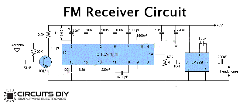
FM Receiver Circuit using TDA7021 & LM386

Sensitive FM Radio Tuner Circuit
AM Radio Receiver | Electrical Engineering | Homework Help
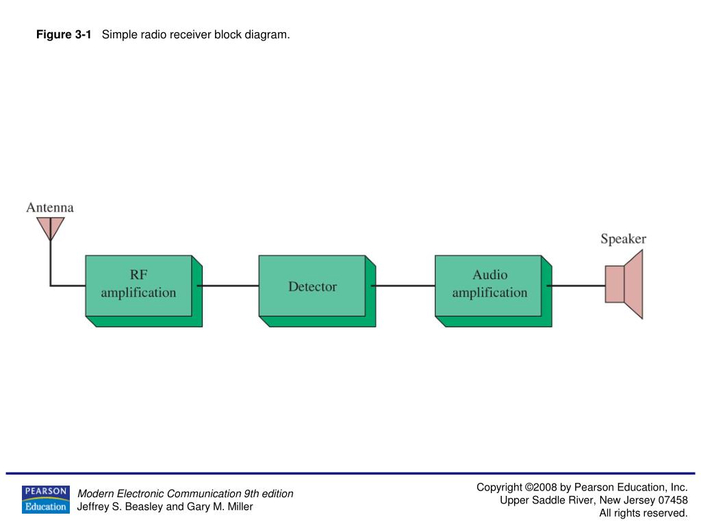
PPT - Figure 3-1 Simple radio receiver block diagram ...
Simplest AM Radio Circuit - Homemade Circuit Projects

Navy Electricity and Electronics Training Series (NEETS ...

A.M. Receiver Tutorial & Circuits - A.M. Receivers - Block ...
Analog Communication - Receivers

Functional block diagram of a radio receiver. A conventional ...
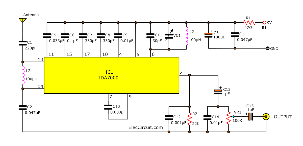
FM receiver circuit with PCB - Simple circuit - Eleccircuit.com

FM Radio Receiver Circuit

Draw the block diagram of an FM receiver and explain its ...
Radio reception: simple, AM and FM receiver

Block diagram of the VHF receiver for receiving FM radio ...
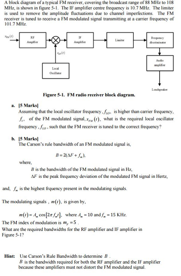
Solved A block diagram of a typical FM receiver, covering ...
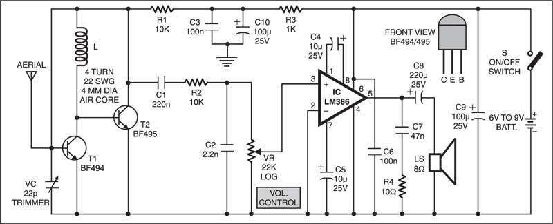
FM Receiver | Electronics Circuit with Full Explanation

Figure 7. RTL2832U block diagram : FM Receiver Based on ...
Superheterodyne AM Receiver - Working with Block Diagram and ...
Comments
Post a Comment