42 split phase motor diagram
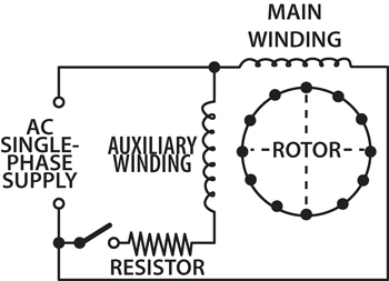
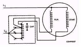
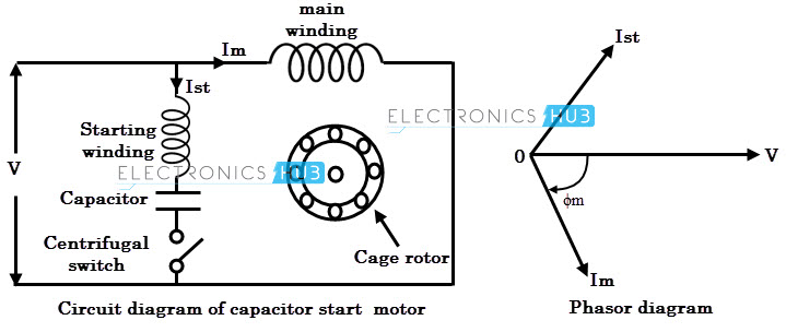
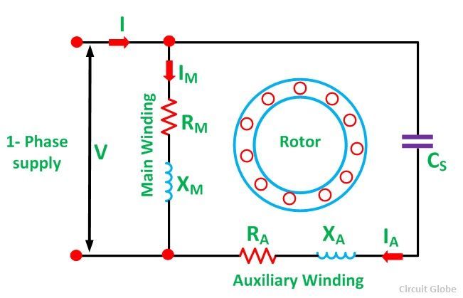
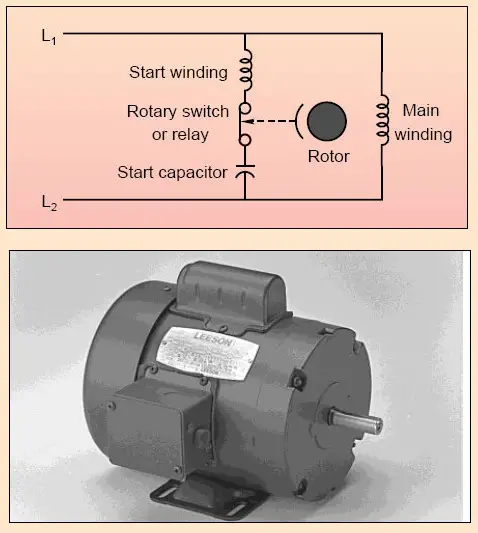
Single Phase Electric Motor Diagrams A Split Phase Capacitor Run type of electric motor has a running capacitor permanently connected in series with the auxiliary winding. The starting capacitor is in parallel with the running capacitor only during the starting period. The motor starts with the centrifugal switch closed. CLICK HERE for Electric Motors and Accessories on Amazon Split Phase Induction Motor | Working & Applications ... A Split Phase Induction Motor is a single phase motor consists of a stator and a single-cage rotor. The stator has two windings i.e. main winding and an auxiliary winding. The auxiliary winding is also known as starting winding. In construction, these two windings are placed 90° apart in space.
Split Phase Induction Motor : Theory, Working, Types & Its ... The split-phase induction motor diagram is portrayed as below: Working of Split Phase Induction Motor Because of the non-uniform rotating field, the current across both the windings is not similar. So, starting torque is minimal which is almost 1.5 - 2 times more than initial running torque. Working of Split Phase Induction Motor

Split phase motor diagram
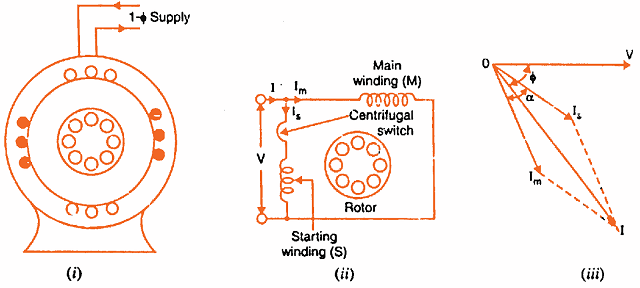
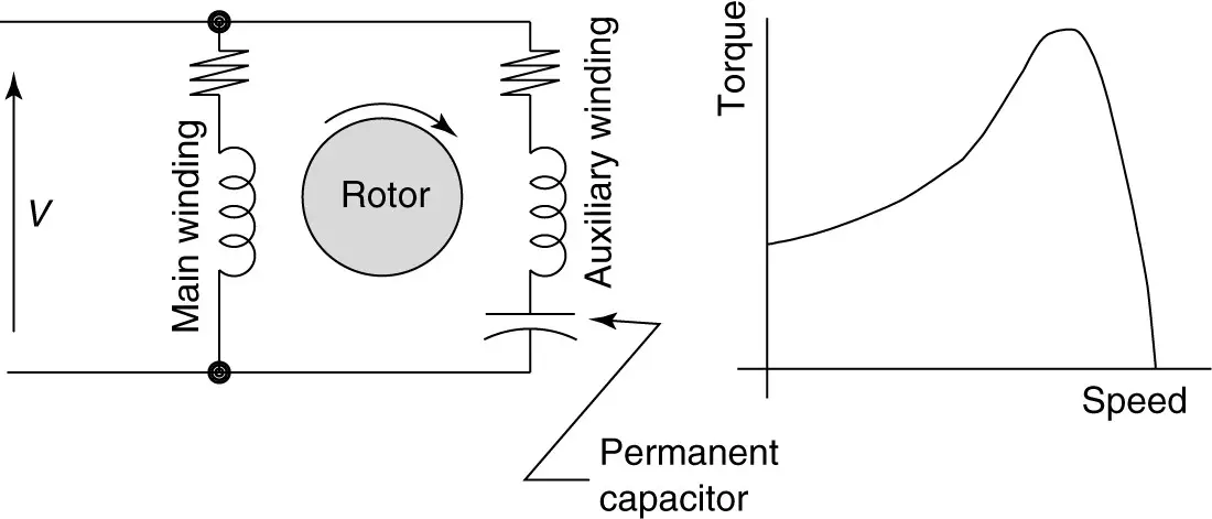
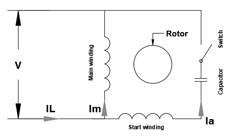
Split-Phase Induction Motor - Operation and Characteristics Operation of Split-Phase Induction Motor When the starting winding of the motor is connected to the source of single-phase AC supply, the starting winding carries a current Is while the main winding carries a current Im as shown in the connection diagram. As the starting winding is made highly resistive whereas the main winding highly inductive. Permanent Split Capacitor (PSC) Induction Motor A permanent split capacitor (PSC) motor is a type of single-phase induction motor. The circuit diagram of a permanent split-phase motor is shown in the figure below. The permanent split-phase induction motor consists of a squirrel cage rotor and the stator has two windings, viz. starting or auxiliary winding and main or running winding. Split Phase Motor - Construction, Diagram, Working ... Fig. 1 : (a) Schematic representation of a split-phase type single-phase induction motor, (b) Connection diagram, (c) Phasor diagram The auxiliary winding along with the series resistor (R) is connected across the main winding.
Split phase motor diagram. Types of Single Phase Induction Motors (Split Phase ... In a split-phase induction motor, the starting and main current get split from each other by some angle, so this motor got its name as a split-phase induction motor.. Applications of Split Phase Induction Motor. Split phase induction motors have low starting current and moderate starting torque. These motors are used in fans, blowers, centrifugal pumps, washing machines, grinders, lathes, air ... What is a PSC motor | ASPINA Sep. 14, 2020. A Permanent Split Capacitor (PSC) Motor is a type of single-phase AC motor; more specifically, a type of split-phase induction motor in which the capacitor is permanently connected (as opposed to only being connected when starting). AC motors can be divided into single- and three-phase motors depending on whether they are driven ... PDF 120 / 240 Vac Single Split Phase & Multi-wire Branch Circuits fig. 1 below illustrates the residential 120 / 240 vac, single split phase, 3- pole, 4 wire grounding system, which was inherited from edison's early dc distribution networks. 120 / 240 vac split phase electrical power from the utility (called service)is fed through an electrical power meter to a load center / breaker panel for further … Motor Connection Diagrams - Electric Motor Warehouse Electric Motor Wire Marking & Connections. For specific Leeson Motor Connections go to their website and input the Leeson catalog # in the "review" box, you will find connection data, dimensions, name plate data, etc. Single Phase Connections: (Three Phase--see below) Single Voltage:
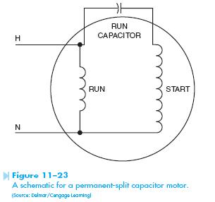
Split-phase electric power - Wikipedia A split-phase or single-phase three-wire system is a type of single-phase electric power distribution. It is the alternating current (AC) equivalent of the original Edison Machine Works three-wire direct-current system. Its primary advantage is that, for a given capacity of a distribution system, it saves conductor material over a single-ended single-phase system, while only requiring a single ... Capacitor Start Motors: Diagram & Explanation of How a ... Thus a capacitor-start induction-run motor produces a better rotating magnetic field than the split-phase motors. It is evident from the phasor diagram that the current through the starter winding Is leads the voltage V by a small angle and the current through the main winding Im lags the applied voltage. Dayton Split Phase Motor Wiring Diagram - Wiring Diagram ... Dayton Split Phase Motor Wiring Diagram November 30, 2020 1 Margaret Byrd 0 Dayton general purpose motor open 4 hp split phase 1725 rpm 120v belt drive 3 practical machinist largest drum switch wiring 2 sd need a 1 voltage 115v ac 48z frame Dayton General Purpose Motor Open Dripproof Rigid Base Mount 1 3 Hp 725 Nameplate Rpm 115v Ac 6xh45 Grainger Permanent Split Capacitor Motor Wiring Diagram The Permanent Split Capacitor motor also has a cage rotor and the two The connection diagram of a Permanent Split Capacitor Motor is shown below. The permanent split capacitor motor is a simple, reliable design, because it has no starting switch nor a starting capacitor. A run type capacitor is connected in.
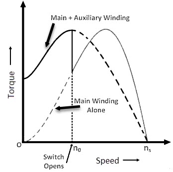
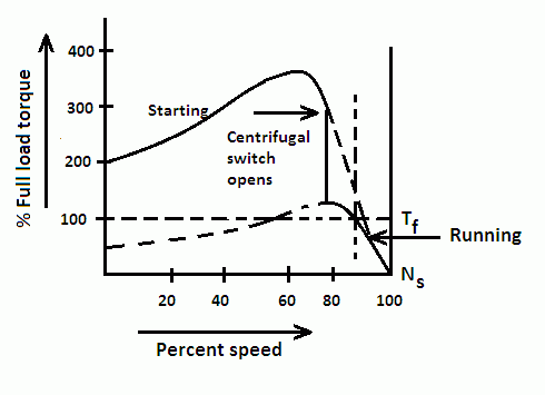
Split phase motor wiring - Learn how single phase motors ... The split-phase machine has two windings from a single phase arranged in the stator. One is the main winding and other is starting winding, which is used only for starting purpose. The main winding has characteristics of low resistance but high reactance. The starting winding has high resistance but low reactance. Split Phase Motor - your electrical guide A typical torque speed characteristics of a split phase induction motor are shown in the figure. The starting torque is about twice the full load torque. The current at starting is about 6 to 8 times. Speed falls with the increase in load with only about 5% to 7% otherwise it is constant speed motor. Speed is governed by the relation Split Phase Motor connection diagram. Split Phase Motor ... Slit Phase Motor Connection Wiring Diagram The split phase motor has no starting capacitor, only a start winding that is disconnected from the line, once the motor reaches about 75% speed. This motor has limited applications due to its low starting torque, and high starting current characteristics. Loads that require Need help wiring a 120 volt AC split phase motor - The ... A "split phase" relies on the start winding resistance to shift phase. Just to be sure you have things right, you might try connecting to the run terminals, giving the motor a good spin, and turning it on right away. If you are correct, it will then run, and will not draw too much current. You should hear a "snick" as the start switch cuts out.

Split Phase Motor - Electrical Engineering Centre
Split Phase Motor Wiring Diagram - Collection - Wiring ... Split Phase Motor Wiring Diagram Source: static-cdn.imageservice.cloud Before reading the schematic, get acquainted and understand all of the symbols. Read typically the schematic like a new roadmap. I print the schematic in addition to highlight the signal I'm diagnosing to make sure I am staying on the path.

Centrifugal Switch: What is it? (And How Does it Work ...
(PDF) Split-phase motor running as capacitor starts motor ... Split-phase motor running as capacitor starts motor and as capacitor run motor Yahaya A. ENESI, Jacob TSADO, Mark NWOHU, Usm an A. USMAN, Odu A. IMORU 400 600 800 1000 1200 1400 1600
AC Motors Part 3-Single Phase Operation | Pumps & Systems
How Split-Phase AC Induction Motor Works - Simple Circuit ... Good application for split-phase motors include small fans, small grinders and blower and the other low starting torque applications with power needs from 1/20 to 1/3 hp. For any applications requiring high on/off cycle or high torque, we have to avoid using this type motor. [Circuit's schematic diagram source: Microchip Application Note]

Split Phase and Capacitor Start Induction Motors
Re-wiring a Dunlap 1/3 HP Thermotron Model #115.5454 Split ... The motor is split-phase. Has a centrifugal switch & a thermal reset switch. Also had an On/Off switch in the motor base. At some point, dad had apparently changed the wiring in the drill press. He installed an On/Off switch on the press itself in order to more easily turn the drill press on and off, rather than reaching all the way back on the ...
Split Phase Motor - your electrical guide
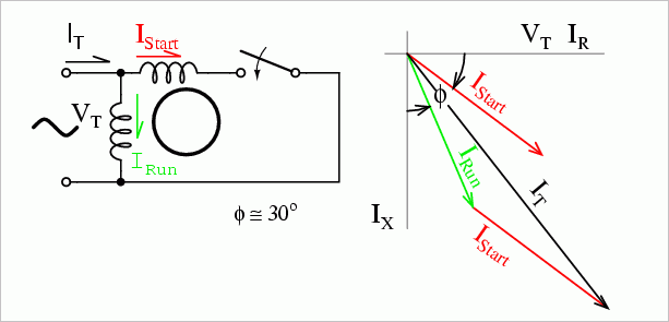
Split Phase Induction Motor : Working, Advantages & Its ... The split phase induction motor phasor diagram is shown below. The flow of current within the IM (main winding) can be lagged after the voltage supply approximately through the 90 degrees angle. Here, IA is the flow of current within the auxiliary winding can be around in phase through the line voltage.
ECN Electrical Forums
Split Phase Induction Motor - Operation and Characteristics Consequently, the currents flowing in the two windings have a reasonable phase difference (25° to 30°) as shown in the phasor diagram in the figure given above. Hence the motor behaves like a two-phase motor. These two currents produce a revolving flux and hence make the motor self-starting.
Does a split phase electric motor require a split phase ...
Split phase Motor | Mike Holt's Forum The so called "split phase motor" is one way. By adding a second winding to the motor, positioning it 90 degrees from the main winding, and feeding a current shifted in phase from the main winding you can create a somewhat rotating magnetic field that will start the motor. This start winding is dropped out when the motor reaches a sufficient speed.
Split phase motor wiring - Learn how single phase motors are ...
[Newbie] - Wiring split phase motor to drum switch | The ... In one of schneiders attachments I was able to find a wiring diagram for a 110V split phase motor, but I am a little perplexed on how to do this. Page 4 shows the wiring diagram I am talking about. Here are some photos from the motor, as well as a distribution block I plan to use.

Types of Single Phase Induction Motors
What is a Split Phase Induction Motor? - Circuit Globe The phasor diagram of the Split Phase Induction Motor is shown below: The current in the main winding (I M) lags behind the supply voltage V almost by the 90-degree angle. The current in the auxiliary winding I A is approximately in phase with the line voltage. Thus, there exists a time difference between the currents of the two windings.

STANDARD SPLIT PHASE MOTORS - ENGINEERING ARTICLES
Types of Single Phase Induction Motors | Single Phase ... Split Phase Induction Motor . Figure 1 illustrates the split-phase induction motor. The split-phase motor relies solely on differences in the resistance and reactance of the windings to produce a phase shift. There is a centrifugal switch in the auxiliary winding circuit that opens as the motor approaches full speed.
Single-phase Induction Motors | AC Motors | Electronics Textbook
Types of Single Phase Induction Motors | Single Phase ... Fig.6: Split Phase Motor Wiring Diagram The split phase motor can be found in applications requiring 1/20 HP up to 1/3 HP, meaning it can turn anything from blades on a ceiling fan, washing machines tubs, blower motors for oil furnaces, and small pumps. The centrifugal switch is a normally close control device that is wired into the start winding.

Split phase motor wiring - Learn how single phase motors are ...
Split Phase Motor - Construction, Diagram, Working ... Fig. 1 : (a) Schematic representation of a split-phase type single-phase induction motor, (b) Connection diagram, (c) Phasor diagram The auxiliary winding along with the series resistor (R) is connected across the main winding.

Split phase motor wiring - Learn how single phase motors are ...
Permanent Split Capacitor (PSC) Induction Motor A permanent split capacitor (PSC) motor is a type of single-phase induction motor. The circuit diagram of a permanent split-phase motor is shown in the figure below. The permanent split-phase induction motor consists of a squirrel cage rotor and the stator has two windings, viz. starting or auxiliary winding and main or running winding.
Split Phase Induction Motor - Operation and Characteristics
Split-Phase Induction Motor - Operation and Characteristics Operation of Split-Phase Induction Motor When the starting winding of the motor is connected to the source of single-phase AC supply, the starting winding carries a current Is while the main winding carries a current Im as shown in the connection diagram. As the starting winding is made highly resistive whereas the main winding highly inductive.

Internal Wiring Configuration for Dual Voltage Dual Rotation ...
Types of Single Phase Induction Motors | Single Phase ...

Single Phase Capacitor Start and Capacitor Run Electric Motor ...

The capacitor-start, split-phase motor
Speed Control of Split-Phase and Capacitor Motors

Types of Single Phase Induction Motors (Split Phase ...
Types of Single Phase Induction Motors
Split Phase Induction Motor | Working & Applications ...
Single Phase Motor Starting – Voltage Disturbance

Electrical Revolution: Split Phase Motor : Construction & Working

This is a Split Phase Capacitor Run Electric Motor Diagram ...

Split Phase Ac Induction Motor Diagram And Symbol Ac - Wiring ...

Resistance split phase induction motor
Permanent Split Capacitor Motor – HVAC Troubleshooting
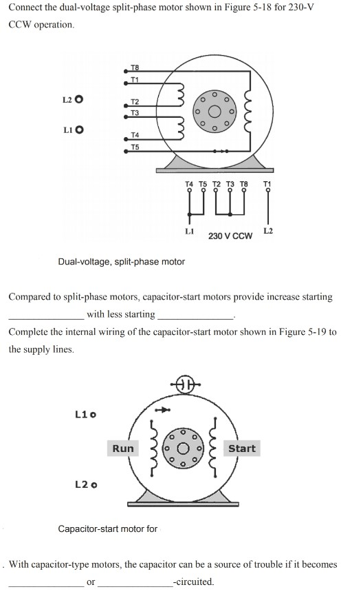
Solved Connect the dual-voltage split-phase motor shown in ...

Split-Phase Motors

Split Phase Induction Motor (with Animation in Hindi)
Split Phase Motor - your electrical guide

Electrical Revolution: Split Phase Motor : Construction & Working
1 Phase Motor Drawings #1 - ECN Electrical Forums

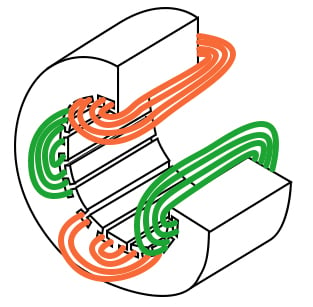
Split Phase AC induction motor winding arrangement diagram ...
Working of SPLIT PHASE, CAPACITOR, SHADED POLE Induction Motor - Basic Electrical Engineering
Split Phase Motor connection diagram. Split Phase Motor ...

Split Phase and Capacitor Start Induction Motors

MrElectrician.TV - A Reactor Start, Split Phase, Induction ...
Permanent Split Capacitor Motor - its Advantages Applications ...
Split Phase and Capacitor Start Induction Motors
Few Words About Capacitor-Start (CS) Motors
Comments
Post a Comment