40 mercury stator wiring diagram
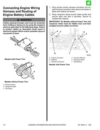
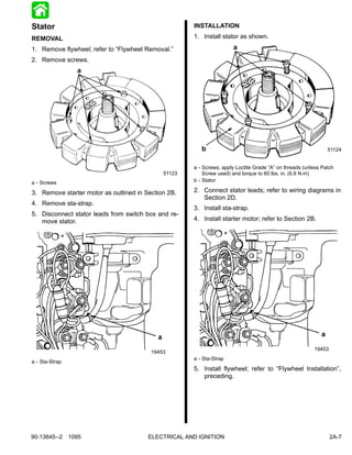
Mercury Mariner Outboard 75 HP Service Repair Manual - Issuu 2. Connect stator leads; refer to wiring diagrams in Section 2D. 3. Install sta-strap. 5. Disconnect stator leads from switch box and remove stator. 4. Install starter motor; refer to Section 2B ... PDF Mercury - Outboard Stators Mercury DVA (Peak Reading) Voltage and Resistance Chart HP Model Year or Serial# Ignition Part Number Stator Trigger Read Ohms DVA Low Spd High Spd Low Spd High Spd Low Spd High Spd Read Ohms DVA 90-350 9-16 Amp 6 CYL Blue to 1976- 1994 4301235- OG201874 Red to 332-7778 114-7778* Gnd Blue/Wht to Gnd Gnd Red/Wht to Gnd 5000-7000 2200- 2400*
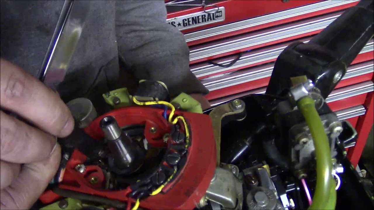
Normal Older Mercury Outboard Wiring - YouTube ..Here we go again- another older Mercury motor with electrical issues. This one is slightly different because it has been in use and running flawlessly. THE...
Mercury stator wiring diagram
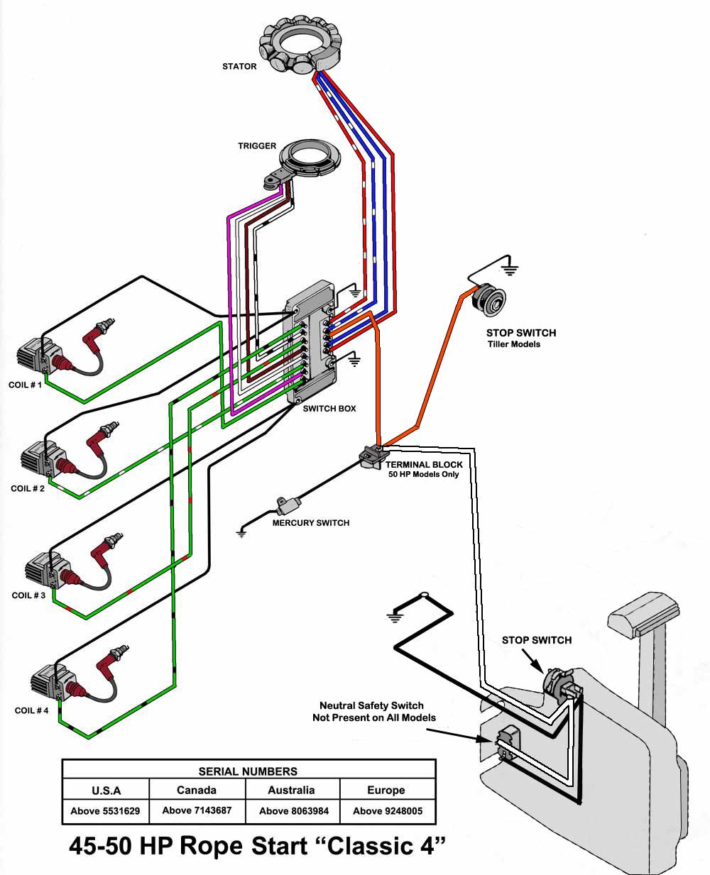
PDF ELECTRICAL AND IGNITION - Motorka.org 200-300 volts Low speed stator is O.K.: Go to Testing Trig-ger Less than 200 volts or intermittent Go to next step. If stator tests O.K., replace switch box. 3. Stator high-speed input to switch box. Connect red meter lead to red stator lead. Connect black meter lead to a good ground. Set meter to 400 DVA scale. 4. Crank motor while reading ... Wiring Color Codes for Mercury & Mariner Outboard Motors. wiring color codes Here is a listing of common color codes for Mercury and Mariner (US-made) outboard motors. These codes apply to later-model motors (approximately early 80's to present) Mercury B398453 Classic Fifty 45 Wiring Diagram Wiring Diagram (PDF) Mercury 4 Cylinder (Magneto). Merc (4-cyl).Mercury & Mariner 45 HP Ignition Parts. Save on stators, switch boxes, triggers, rectifiers, voltage regulators and internal wiring harnesses for Mercury and Mariner 45 HP outboards. Parts manufactured by CDI Electronics meet or exceed OEM specifications.
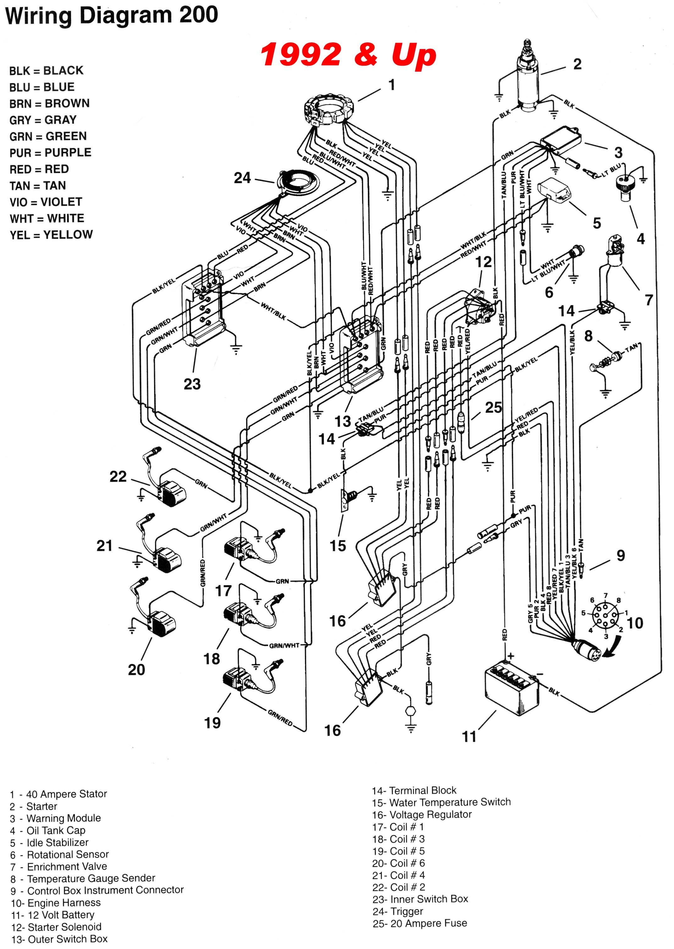
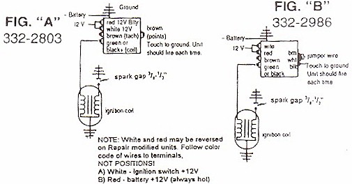
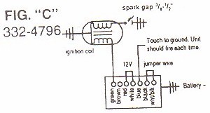
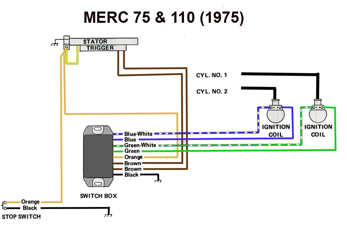
Mercury stator wiring diagram. Mercury 90 Hp Wiring Diagram - Free Wiring Diagram Online Mercury 90 hp wiring diagram. Feb 17, 2013 #2 re: Mercury outboard wiring diagram ignition switch wiring diagram is a simplified tolerable pictorial representation. Models Ser # 4301235 To 5129480. Randy (tuesday, 11 may 2021 01:17) im looking for any and all service manuals for a 2000 mercury 60 hp elpto, outboard. PDF MERCURY/MARINER ★ Precise lead lengths eliminate the concern of excess wire getting in the way of moving parts. ★ Best warranty in the industry. 18-5864 STATOR & KIT Replaces: 86617A20 For: 6-25 HP APPLICATION BEGINS ON PAGE 256 MERCURY/MARINER 8 Pole Stator Wiring Diagram Xrm This is the 6 coil stator common on most 50cc scooter but also can be found on a cc too. The wire colors 8 coil stator. 11 coil stator Here is a wiring diagram of the typical 5-wire CDI system on a lot of scooters which in most instances is. 7/8/ Dan's Motorcycle Flywheel Magnetos High Tension Magnetos have the ignition coil on the stator plate under the Flywheel. Mercury Stator Wiring Diagram - autocardesign Mercury Stator Wiring Diagram- wiring diagram is a simplified standard pictorial representation of an electrical circuit.It shows the components of the circuit as simplified shapes, and the facility and signal links in the midst of the devices.
1989 Force 35hp Wiring Diagram - schematron.org Mercury/Force CDM Ignitions Troubleshooting. 2, 3 and 4 OMC Stern Drive Electronic Shift Assist Applications and Wiring Diagrams. Ignition. Lookup Force 35 hp () outboard motor parts by serial number range and buy discount parts from our large online inventory.Apr 18, · I got a 35 hp Force that needs some wiring work on the engine, and I am ... Mercury Stator Wiring Diagram - easywiring Mercury outboard rectifier wiring diagram mercury outboard rectifier wiring diagram every electric structure is made up of various unique pieces. 88 results for 25 hp mercury stator save 25 hp mercury stator to get e mail alerts and updates on your ebay feed. Mercury Outboard Wiring Diagram Schematic - Wirings Diagram Mercury Outboard Wiring Diagram Schematic - mercury outboard wiring diagram schematic, Every electric arrangement consists of various unique pieces. Each component should be placed and connected with different parts in particular manner. If not, the arrangement will not work as it should be. Wiring Diagram 40 Hp Mercury Outboard - 4K Wallpapers Review Wiring Diagram 40 Hp Mercury Outboard Untitled. Previous Next. Suggested Wallpapers: 2002 40 Hp Mercury Outboard Wiring Diagram, Related Gallery: Home Electrical Wiring Blueprint And Layout Pdf | Raspberry Pi 3b Schematic Diagram | Pull Wire Tool | 2021 Nissan Sentra Fuse Box Location | 240v Light Switch Wiring Diagram Australia | Panel Wiring Diagram Pdf | Range Rover Sport Wiring Diagram ...
Mercury Outboard Wiring diagrams -- Mastertech Marin Mercury Outboard Rectifier Wiring Diagram - Wirings Diagram Mercury Outboard Rectifier Wiring Diagram - mercury outboard rectifier wiring diagram, Every electric structure is made up of various unique pieces. Each component ought to be set and linked to different parts in particular manner. If not, the structure will not work as it should be. Mercury 40 Elpto Wiring Diagram 40/50 EHPTO Wiring Diagram a - Trigger m - Fuel Enrichment Solenoid b - Stator n - Trim Pump c - Key. I have a Mercury 40 ELPTO 2 Stroke on a Sport, I have ordered the and they do seem to be connected in the block wiring harness. Stator Wiring Problem | Boating Forum - iboats Boating Forums Re: Stator Wiring Problem Yes the 174-5454-K1 is the stator for your engine, what you have is part of a red stator kit for a mercury engine I can't tell from the picture what it is for sure, I think that they all come with a regulator. I can't tell you for sure as we don't use the junk stators that merc builds.
Print Out This Guide: Mercury Outboard Troubleshooting ...
PDF Mercury Mariner Wiring Diagram - Discount Marine 472 WIRING DIAGRAMS Engine wire harness connector plugs 1 4 Charging coil 2 5 Charging coil Shift interrupt switch Throttle position sensor Plug cap Oil pressure switch Crankshaft position sensor(s) Engine temp. sensor Adapter harness (S.N. OT320116 & prior) ECU 75 AND 90 HP MODELS. WIRING DIAGRAMS 473 13 Diagram Key Connectors Ground Frame ground

Tachometer Wiring
Page 39 - Mercury Mariner outboard ignition test specs The charts on this page provide specs for testing your Mercury Mariner outboard ignition components. Outboard ignition parts for Mercury Mariner outboard motors. Power pack, stator, timerbase, regulator. ... Stator Wire to wire. Trigger (ohms) Trigger (DVA) Trigger Wire to wire. Ignition Coil (ohms) Primary | Output. 4. 1972-1975. 3296137 ...
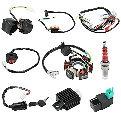
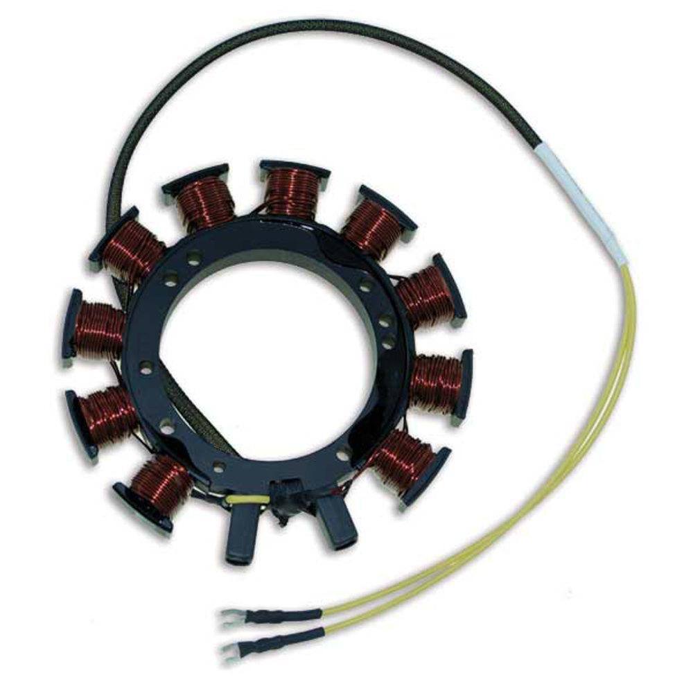
Buying Guide | TUELETFU, CDI Electronics Stator for Mercury 6 ...
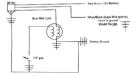
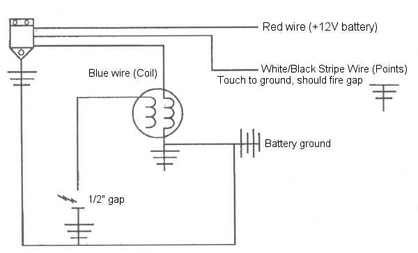
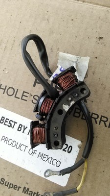
Mercury Tech Wiring diagram of mercury "black" stator ... Black stator, pg 83, appears that red wire and red whote wire are connected, as are blue and blue white, neither run to ground. I would use the cdi resistance values, mike the existing wire dameter, use the chart of magnet wire i posted link to.
SERVICE INFO – Inland Marine | Sales and Service
Mercury Tech Wiring diagram of mercury "black" stator ... I need a wiring diagram for mercury red stator. By Forced in forum Technical Discussion Replies: 0 Last Post: 06-03-2005, 10:16 AM. Wiring diagram Red Stator. By Forced in forum Posting Questions and Suggestions Replies: 1 Last Post: 06-01-2005, 07:20 PM. Tags for this Thread ...
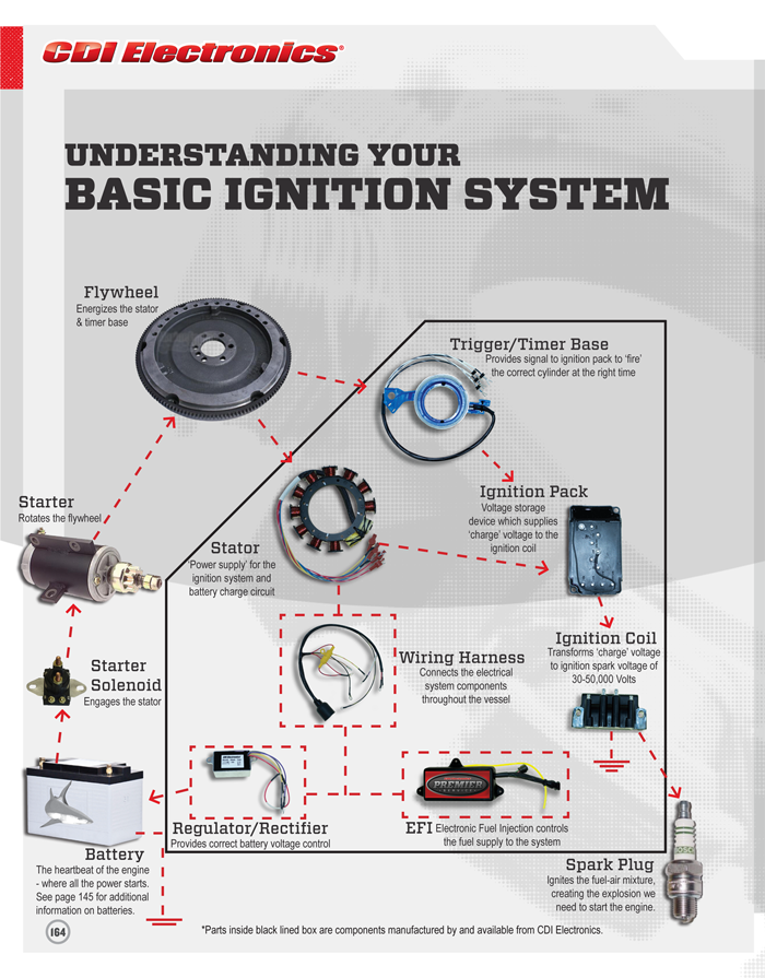
ELECTRICAL AND IGNITION
Mercury B398453 Classic Fifty 45 Wiring Diagram Wiring Diagram (PDF) Mercury 4 Cylinder (Magneto). Merc (4-cyl).Mercury & Mariner 45 HP Ignition Parts. Save on stators, switch boxes, triggers, rectifiers, voltage regulators and internal wiring harnesses for Mercury and Mariner 45 HP outboards. Parts manufactured by CDI Electronics meet or exceed OEM specifications.
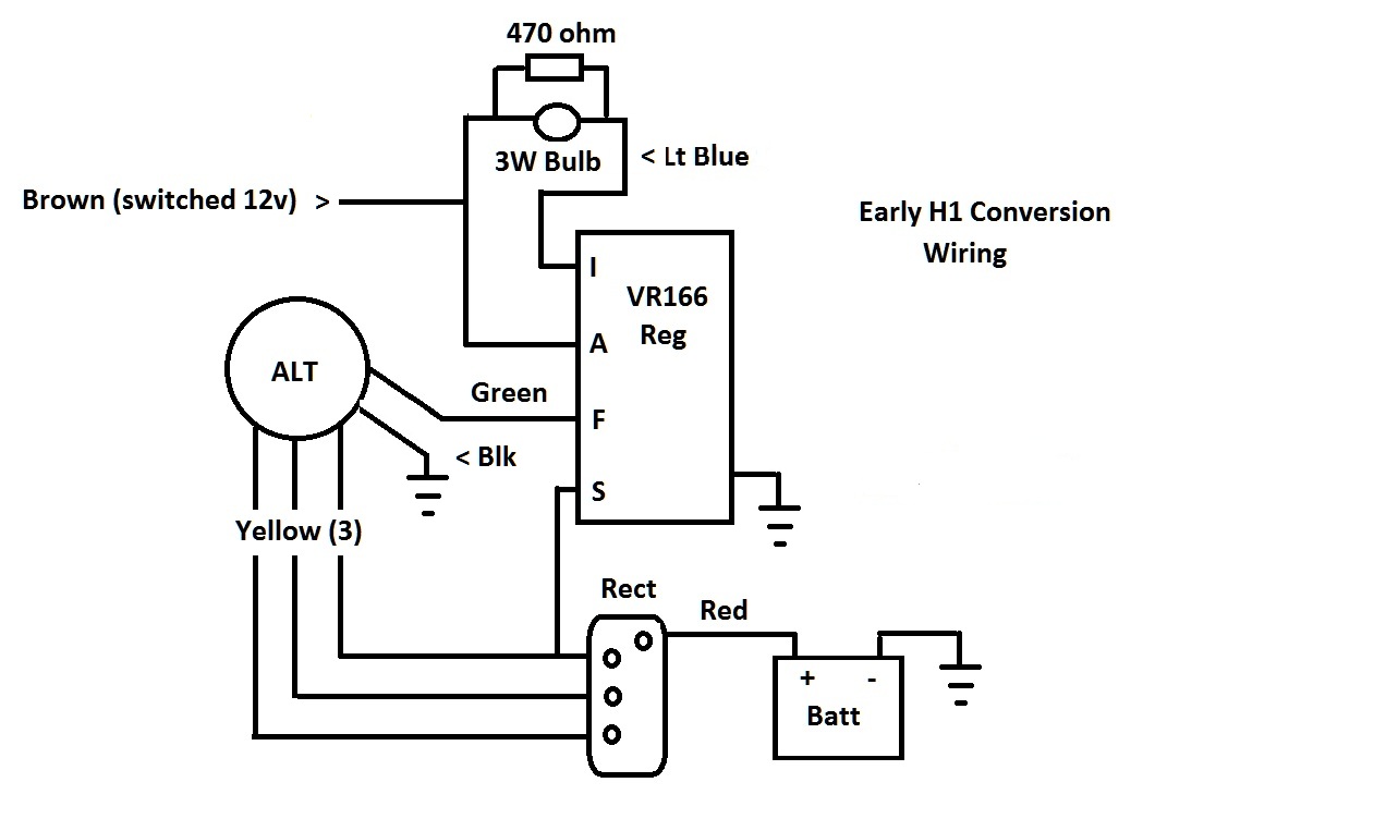
Regulator/Rectifier Conversion
Wiring Color Codes for Mercury & Mariner Outboard Motors. wiring color codes Here is a listing of common color codes for Mercury and Mariner (US-made) outboard motors. These codes apply to later-model motors (approximately early 80's to present)
Mercury Outboard Wiring diagrams -- Mastertech Marin
PDF ELECTRICAL AND IGNITION - Motorka.org 200-300 volts Low speed stator is O.K.: Go to Testing Trig-ger Less than 200 volts or intermittent Go to next step. If stator tests O.K., replace switch box. 3. Stator high-speed input to switch box. Connect red meter lead to red stator lead. Connect black meter lead to a good ground. Set meter to 400 DVA scale. 4. Crank motor while reading ...
Mercury mariner outboard 90 hp service repair manual
Mercury 7.5hp and 9.8hp 2-Stroke Twins, Fixing Old Ignitions & Setting Points
Mercury Outboard 2.5 and 3.0L V6 and Gearcase FAQ
Mercury mariner outboard 90 hp service repair manual

mercury 120hp force straight4 trigger question | Antique ...
Battery or stator? SOLVED Im Dumb :-p -
Print Out This Guide: Mercury Outboard Troubleshooting ...

New Basic Engine Wiring #diagram #wiringdiagram #diagramming ...
1994 Mercury 175 Voltage Regulator Wires - The Hull Truth ...

Kill cord wiring for Mercury Inline 6 -
Print Out This Guide: Mercury Outboard Troubleshooting ...
Wisonsin Motors Canada - Identifying Wisconsin Charging Sytems
Mercury Outboard Wiring diagrams -- Mastertech Marin
1996 Mariner - Voltage regulator replacement

FLYWHEEL AND STATOR PLATE ASSEMBLY - Serial Range Outboard ...
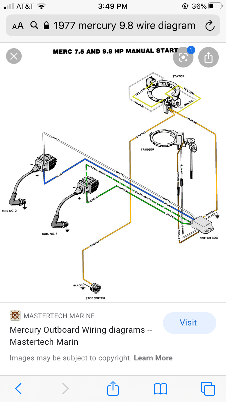
1977 Mercury 9.8 - The Hull Truth - Boating and Fishing Forum
1985 Johnson V4 ignition wiring | Boating Forum - iboats ...
Mercury Outboard Wiring diagrams -- Mastertech Marin

Sport Jet 90 Black to Red Stator Conversion - With Pics ...
Mercury Outboard Wiring diagrams -- Mastertech Marin
Untitled
1998 Mercury Mariner 6, 8, 9.9 15 hp STATOR ASSEMBLY 86704A10 LIGHTING COILS | eBay
XS500 Custom Harness Help | DO THE TON
Untitled
Untitled

Amazon.com: CDI Electronics 414-2770 Mercury/Mariner Wiring ...

Mercury Force Outboard Parts 50 H.P. (1987) 507Y7C looking ...

I have. 1988 mercury Marine. 9.9hp I need the wiring diagram ...
CDI Electronics Stator - 4/6 Cyl. 10 Amp for Mercury/Mariner (1969-1979) 174-4793

FLYWHEEL, STARTER MOTOR AND STATOR - 1980 Outboard 115 [ELPT ...
alternator stator testing--what's up with the 6 wires? - Ford ...

Mercury | MERCURY | 1150 | 3525441 THRU 4855152 | FLYWHEEL ...
Outboard Spares Blog - Troubleshooting 2 Stroke Ignition Problems
Comments
Post a Comment