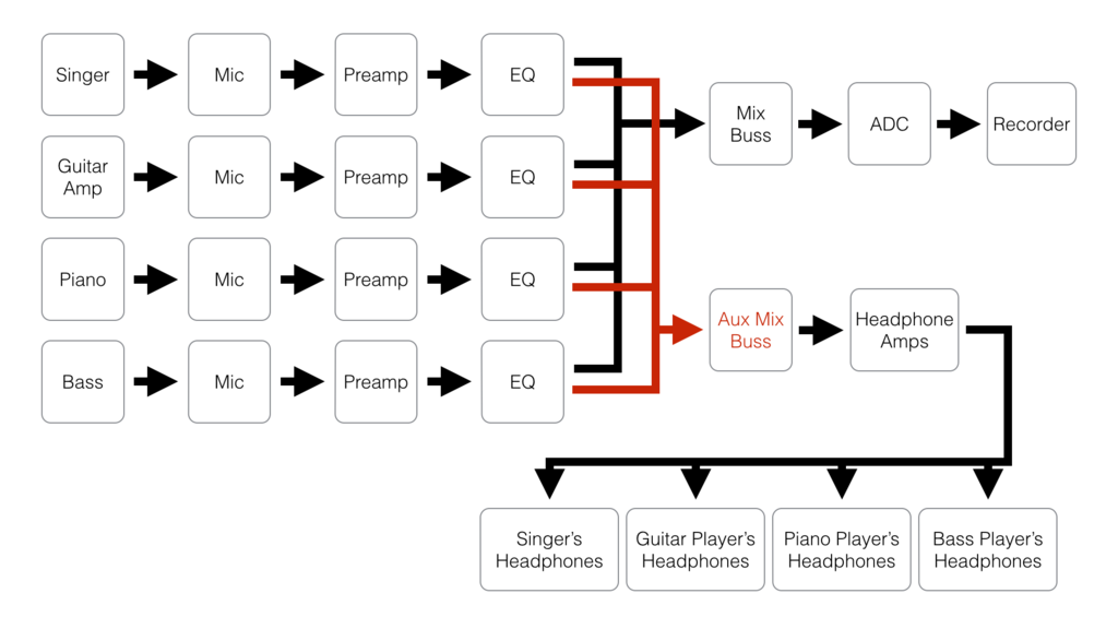
39 audio signal flow diagram
Basic Crystal Oscillator Circuit - crystal oscillator ... Basic Crystal Oscillator Circuit - 16 images - colpitts oscillator what is it circuit diagram how to, resistor parallel oscillator, 24 hr digital clock only with basic cmos chips 5 steps, vco voltage controlled oscillator basic circuit, Electronic Circuits and Diagrams-Electronic Projects and ... We feature 2000+ electronic circuits, circuit diagrams, electronic projects, hobby circuits and tutorials, all for FREE! Since 2008 we have been providing simple to understand educational materials on electronics for engineering students and hobbyists alike.
Getting Started with Stateflow Video - MATLAB & Simulink Later, we'll make the usage rate an output signal and use its value to adjust the battery level of charge in Simulink. There's no cost for using the battery since its energy comes from the sun. On the other hand, when using the grid, the energy price is $0.20 per kilowatt hour, meaning the energy cost will go up by $10 every 15 minutes.

Audio signal flow diagram
Best Stereo Amplifier Reviews (APR. 2022) - AudioJudge The factors of the amplifiers' specs include distortion levels, power rating, signal to noise ratio, and dynamic headroom of the amp.The signal to noise ratio is a major factor which tells you about the capability of the amplifier to convey the listeners with the sufficient audio power at the required time, and also the sound quality level. How to build a Simple Solar Powered Automatic Garden Light N-Channel MOSFET Q2, IRF540N is used for charge controlling operation. Potentiometer R1 is used to set the battery voltage level by controlling the gate voltage across the N Channel MOSFET Q2. The Schottky rectifier diode D1 is SR160, a 1A 60V Schottky diode that is used to protect the battery from reverse polarity as well as to block the reverse flow during discharging conditions. Manual: AudioGroup Inspector - Unity This meter shows the audio signal levels at that point in the signal chain (just after attenuation is applied). This means that if you have DSP effects or Receives after the Attenuation Unit, the metering information seen in the AudioGroup strip for that AudioGroup will be different to the metering information at the Attenuation Unit.
Audio signal flow diagram. CDi 1000 | Crown Audio - Professional Power Amplifiers Features. Extremely versatile; rated for 2-, 4-, 8-ohm loads and 70V and 140V outputs. Switch-mode universal power supply. Intuitive front-panel LCD screen for quick, easy configuration. Onboard digital signal processing includes crossovers, EQ filters, delay, and output limiting. Up to 20 user defined DSP presets are available. 24 Volt 5 Ampere Power Supply Circuit 24 Volt 5 Ampere Power Supply Circuit. In this project, we will demonstrate a 24V 5A power supply circuit utilizing the LM7824 voltage controller IC and TIP2955 transistor. The purpose of a power supply is to provide electric power to an electric load. This is an ideal circuit to utilize where you have the necessities of 24V with high current flow. Potentiometer Connection, Circuit Diagram, Wiring Guide ... 27/01/2021 · This means that the signal starts with the second terminal, then backs to terminal three. Consequently, the second terminal should be connected to the part that sends the basic signal out of the system. This would mean the wired terminal two like an output jack on a guitar and similar to the speaker output terminal on an integrated audio ... Digital Signal Processing - Complete Guide With Examples Music or audio is recorded and the Analog signals are captured. ADC converts the signal to a digital signal. The digital processor receives the digitized signal as input, processes it, and stores it. During playback, the digital processor decodes the stored data. DAC converter converts the signal to analog for human hearing.
Recognition Algorithm of Piano Playing Music in ... The traditional autocorrelation method is used to extract the fundamental frequency of an audio signal. The experimental results are shown in Figure 3. Figure 3(a) is a short-time energy waveform diagram of an audio signal. The horizontal axis is the time axis, and the vertical axis is the normalized short-term energy amplitude. Recording Studio Setup Diagram - audio patchbays patch ... Recording Studio Setup Diagram - 16 images - home recording studio project things needed to setup a, 32 best images about recording studio designs on pinterest, ssl 4000 patch bay politusic, 32 best images about recording studio designs on pinterest, Best Computer microphones of 2022 | VentureBeat The polar diagram can be defined as the focal length of the sound. This is the pickup angle that the microphone is estimated to have. This factor depends, among others, on the level, direction ... Emitting Audio Frequencies on Command with NI DAQ Devices Follow the diagram on your phone jack to connect the terminals to the analog output channel and ground. Software Instructions Map Your Program Flow and Start With an Example. For our application, we want to emit an audio frequency on command.
Sequence Diagram Tutorial - Complete Guide with Examples The message flow of the sequence diagram is based on the narrative of the particular use case. Then, before you start drawing the sequence diagram or decide what interactions should be included in it, you need to draw the use case diagram and ready a comprehensive description of what the particular use case does. Computer Sc IT & Management - Blogger Audio digitizer. Most computers have a microphone jack, where you can connect an analog microphone. The analog input (the audio signal) is processed in the computer by a discrete sound card, or by audio hardware on the motherboard itself. This data can then be used by software running on the computer. Systems engineering - Wikipedia Systems engineering is an interdisciplinary field of engineering and engineering management that focuses on how to design, integrate, and manage complex systems over their life cycles.At its core, systems engineering utilizes systems thinking principles to organize this body of knowledge. The individual outcome of such efforts, an engineered system, can be defined as a combination of ... EarLevel Engineering Tremolo: First, simulate a musical signal with three harmonics by setting A1 to 100 Hz at 60%, A2 to 200 Hz at 50%, A3 to 300 Hz at 40%. With all B amplitudes at 0%, the result is zero. Reveal the signal by setting B1 to 0 Hz at 100%. Now set B2 to 10 Hz, and bring up its amplitude—you'll see the sidebands, responsible for the richness of the tremolo effect, created around each signal ...
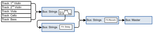
Cubase Signal Routing
The best new free music-making software: essential ... Higher Hz have provided a conveniently labelled signal flow diagram to illuminate the internal workings of the plugin and help you achieve the sound you're after - or discover a sound you weren't expecting.
Signal Flow | SoundGirls.org
Wiring Expert Group: Ford F150 Radio Wiring Diagram 1997 ford f150 radio wiring diagram. Knowing your 2020 ford f150 radio wire colors makes it easy to change your car stereo. Source: . It's a 6 cd, am/fm with 6 speaker unit. If not, the structure won't work as it. Source: . 2018 f150 stereo wiring diagram.

STAGE TUTORIAL Basic Signal Flow Sound System Setup.mp4 - YouTube
Two-stage amplification of an ultrasensitive MXene-based ... Although the center frequency of our eardrum is around 3 kHz, the resistance response to a different word is well synchronous to original audio signals, as shown in Fig. 4A and fig. S6. The characteristic peaks of each word recorded by our device are retained and reflected with fidelity.

Analog Recording Signal Flow (Diagrams + How Does It Work?)
Subaru Forester (2013-2018) Fuse Diagram - FuseCheck.com Fuse box diagram (fuse layout), location, and assignment of fuses and relays Subaru Forester mk4 / SJ (2012, 2013, 2014, 2015, 2016, 2017, 2018).
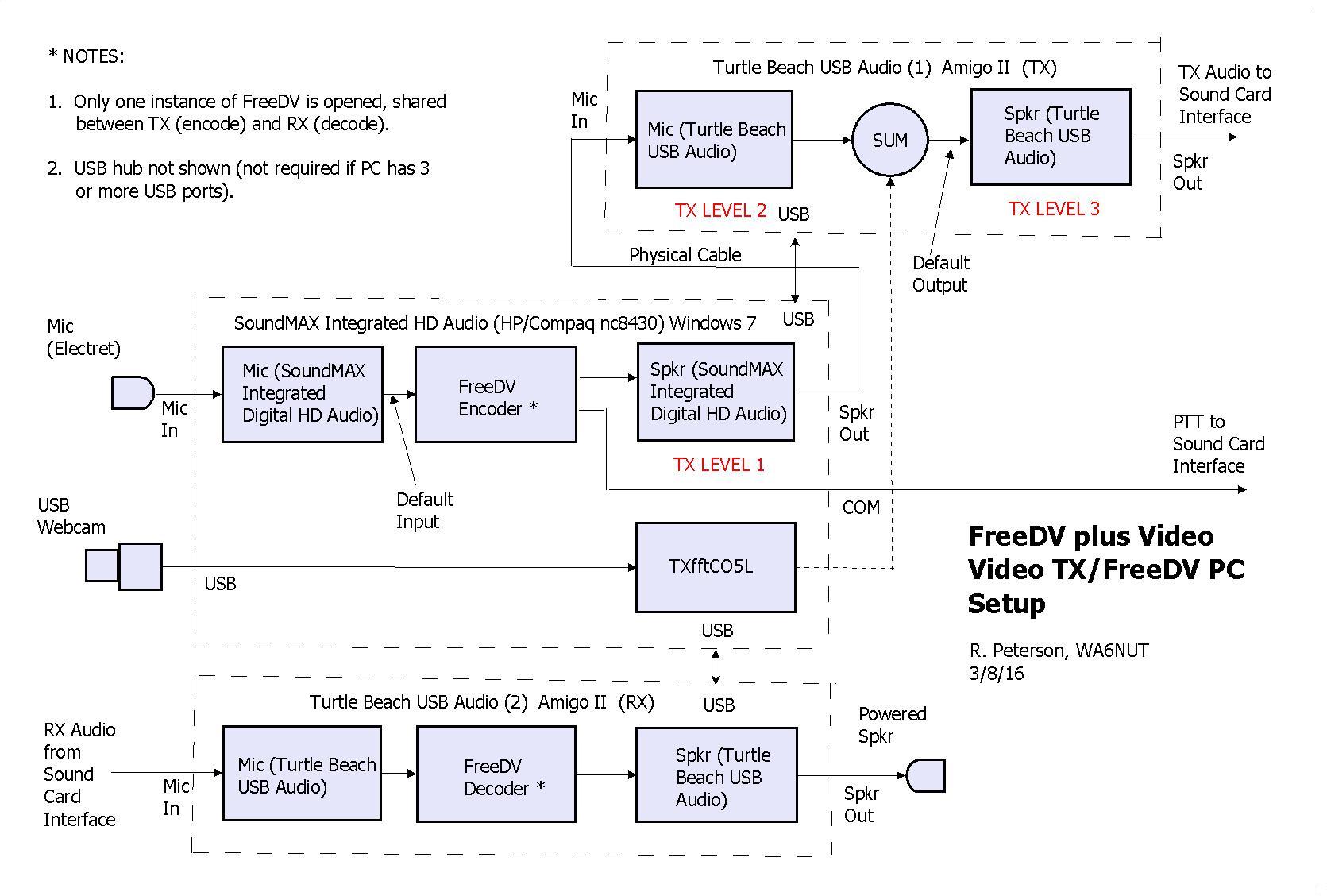
FreeDV plus Video
Chevrolet Malibu (2008-2012) Fuse Diagram - FuseCheck.com Fuse box diagram (fuse layout), location and assignment of fuses and relays Chevrolet Malibu (LS, LT, LTZ, 1LT, 2LT) (2008, 2009, 2010, 2011, 2012).

7. signal flow synths - Beat Lab
TesiraFORTÉ X - Biamp Cornerstone TesiraFORTÉ X is designed to be used primarily with Biamp's beam-forming microphones, PoE amplifiers and speakers. A system including these elements and a UC-room system, display and camera will provide a complete technology solution for a UC-enabled conference room.
Signal flow for volume/panning in general and for multi ...
Michael S. McCorquodale, Ph.D. Fig. 1: Direction of electron and current flow in a basic vacuum tube relative to the cathode and anode. Current will flow only if the voltage on the plate is positive relative to the cathode. If this is not the case, then current does not flow.
Printable Audio Signal Flow Chart - Cockos Incorporated Forums
PreSonus Forums | Studiolive AR16 Usb as an audio ... I've looked at the signal flow diagram and it's been helpful. I only wish we could control the DAW faders with the AR16's ones but that would be too much to ask for the price. If anyone knows the latency and how solid the ASIO drivers are, I'd be grateful.

PreSonus Studio One DAW signal flow diagram. It's important ...
AN5027 Application note - STMicroelectronics digital signal. The STM32 MCUs and MPUs acquire digital data from the microphone(s) through particular pe ripherals to be pr ocessed and transformed into data standard for aud io. The audio data is then handled by the microcontroller according to the targeted audio application. Figure 1. Example of sound acquisition in audio application. a. Arm ...

PreSonus Studio One DAW signal flow diagram. It's important ...
Low Latency Audio - Windows drivers | Microsoft Docs 14/12/2021 · Delay between the time that a user taps the screen until the time that the signal is sent to the application. Touch-to-sound latency: Delay between the time that a user taps the screen, the event goes to the application and a sound is heard via the speakers. It is equal to render latency + touch-to-app latency. Windows Audio Stack. The following diagram shows …

Signal Flow Diagram | Vegas Pro
SIP Tutorial | Explanation on the basics of Session ... Diagram of a request, acceptance, setup and termination of a call. SIP typically sends these messages in UDP (User Datagram Protocol) on port 5060, with 5061 used for a second line on a two line ATA* (see below). Included in the invitation, when setting up a call, are parameters describing exactly what form the audio or video will use.
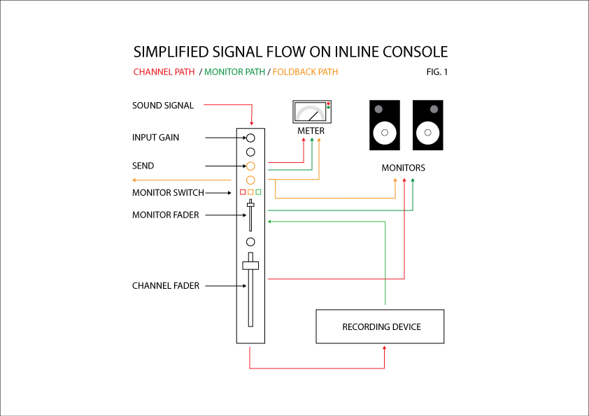
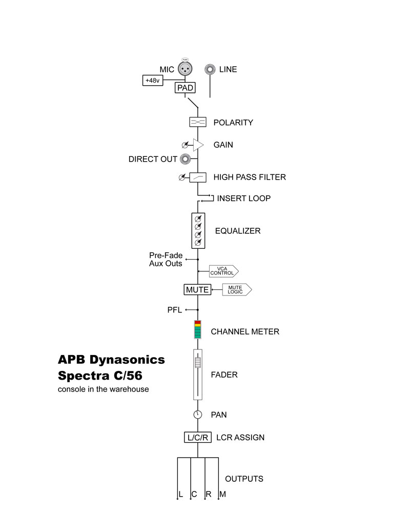
How to Follow Signal Flow on a Large Format Mixing Console ...
How Astable Multivibrator using Logic Gates work | Example ... We enter the signal as the input of each gate. It has a little delay time before appearing at that output. Here is a step-by-step process. Look at the circuit diagram again. Suppose that the input of IC1a is "0", output at pin 3 will is "1". This signal "1" will come to the input of IC1b and provide the output is "0".

Miniclone - Eurorack Signal Flow Transparent PNG - 1024x912 ...
Signal flow chart questions - Gearspace.com Signal flow chart questions. Hello. Is the diagram below accurate? Is the Headphone Amp and Monitor Management necessary? And I have an Apollo UAD2 Duo interface.

Illustration of signal flow in proposed system. Please refer ...
DDSP: Differentiable Digital Signal Processing - Magenta 15/01/2020 · The signal from each synth is combined and run through a reverberation module to produce the final audio waveform. The loss is then computed by comparing spectrograms of the generated audio and source audio across six different frame sizes. Since all the components are differentiable, including the spectrograms, we can train the network end-to using …

Downloadable Charts to Understand Audio Signal Flow in a DAW
Audio Amplifier Circuit - The Engineering Knowledge PIN 2 is input conversion and ground connection A fixed Pin 3 connected to the audio signal PIN 4 is GND Pin 5 is a result that gives an output signal PIN 6 is Vcc where the input is given Pin 7 is a pass where the decoupling capacitor is the connector Component of Circuit The components used for this project are listed here. Battery Capacitor disc

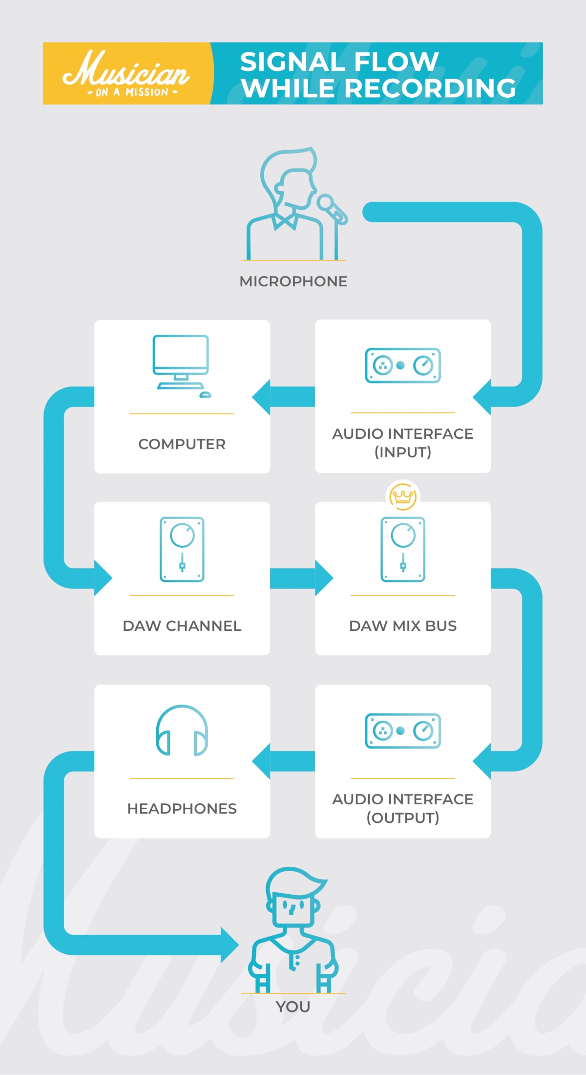
Setting Up a Simple Home Music Recording Studio - PEDAL POINT ...
Very simple amplifier circuit using transistor 2N3904 When there is an input signal, it will pass through C1. To filter out only the sound signal, then feed to Q1 at lead B. It is the first expansion (preamplifier). Which designers organize the amplifier circuit in the common-emitter form. And, there are R1 and R2 to connect in the voltage divider circuit for the Q1.

Detailed Signal Flow Diagram for "ES E" plugin - Gearspace.com
Manual: AudioGroup Inspector - Unity This meter shows the audio signal levels at that point in the signal chain (just after attenuation is applied). This means that if you have DSP effects or Receives after the Attenuation Unit, the metering information seen in the AudioGroup strip for that AudioGroup will be different to the metering information at the Attenuation Unit.

Encyclopedia of Home Recording: Signal Flow
How to build a Simple Solar Powered Automatic Garden Light N-Channel MOSFET Q2, IRF540N is used for charge controlling operation. Potentiometer R1 is used to set the battery voltage level by controlling the gate voltage across the N Channel MOSFET Q2. The Schottky rectifier diode D1 is SR160, a 1A 60V Schottky diode that is used to protect the battery from reverse polarity as well as to block the reverse flow during discharging conditions.

Signal Flow
Best Stereo Amplifier Reviews (APR. 2022) - AudioJudge The factors of the amplifiers' specs include distortion levels, power rating, signal to noise ratio, and dynamic headroom of the amp.The signal to noise ratio is a major factor which tells you about the capability of the amplifier to convey the listeners with the sufficient audio power at the required time, and also the sound quality level.

Signal Path | Douglas Anderson Electronic Music I and II
5.1.4 Signal Path in an Audio Recording System – Digital ...
Downloadable Charts to Understand Audio Signal Flow in a DAW
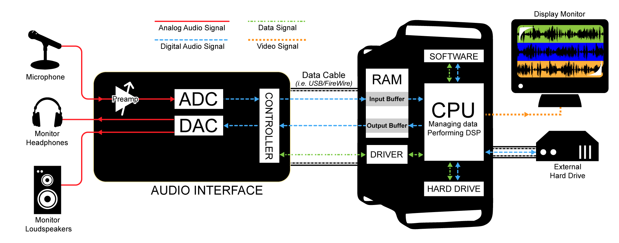
Audio signal flow - Wikipedia

Signal Flow Diagrams | Acid Pro
Csound Journal

SKRATCHWORX™ v2 - Sends and Returns
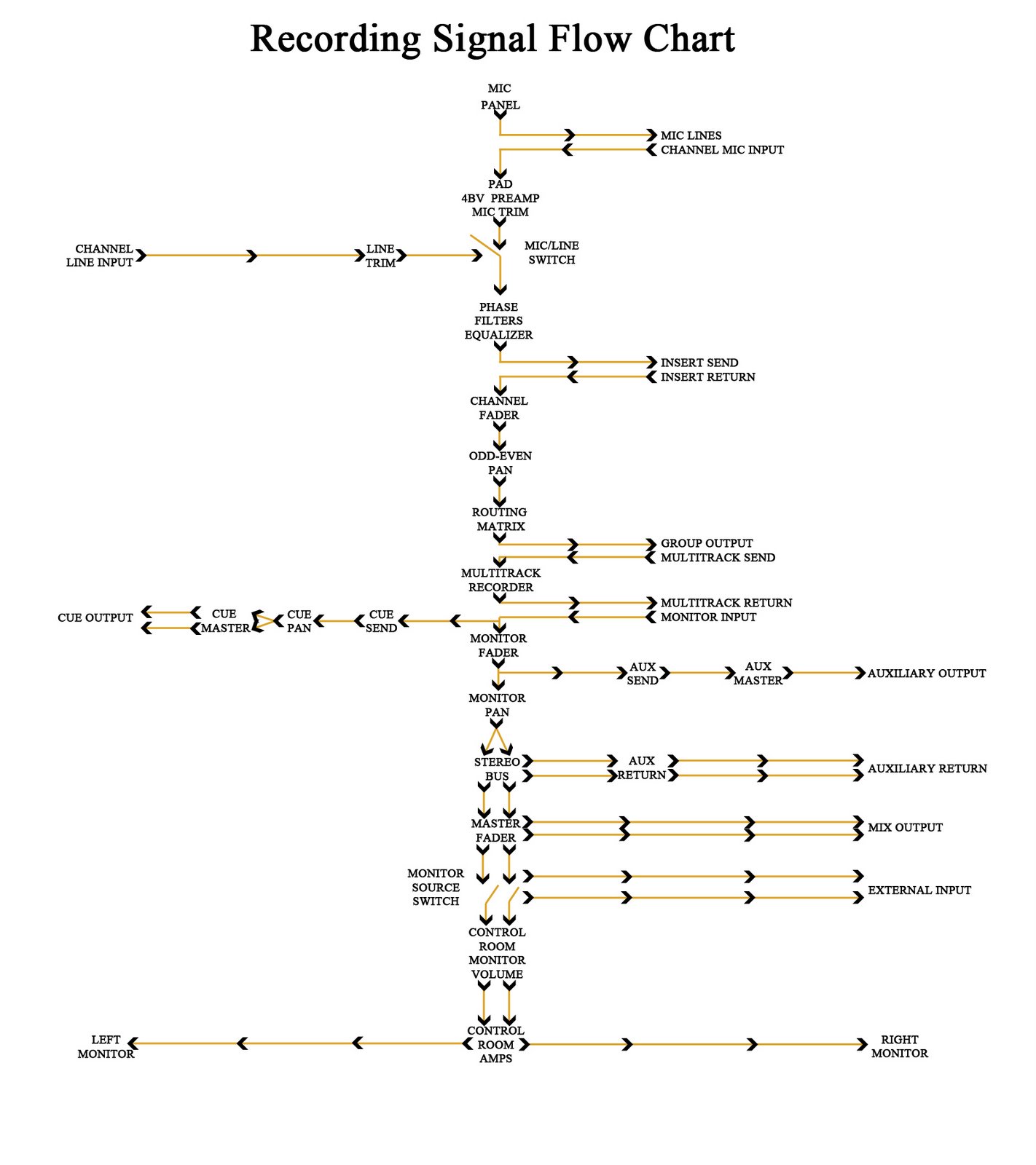
Recording Signal Flow Chart | freqmix
OT: Audio Signal Flow diagram standards?

From Source to Output: Audio Signal Flow for Videographers ...

EETimes - Understanding superior professional audio design: A ...
Church Sound: Signal Flow & Console Operation - ProSoundWeb
Audio Signal Flow: What It Is and How to Use It
Revelation Signal Flow Pt.1- Integrity vs. Fidelity ...

Using An Audio Analogy To Breakdown the Marketing Funnel

Getting Started with Gain Staging | PreSonus

Analog Recording Signal Flow (Diagrams + How Does It Work ...

Signal Flow - Signature Sound

MUX-8258-4C (-8C) 3G / HD / SD SDI Analog Audio Embedder ...

Audio Signal Flow: What It Is and How to Use It
Comments
Post a Comment