39 24 volt alternator wiring diagram
4 Wire Alternator Wiring Diagram - Collection - Wiring ... 4 Wire Alternator Wiring Diagram from infinitybox.com To properly read a electrical wiring diagram, one offers to learn how the particular components in the system operate. For instance , if a module is usually powered up and it sends out a new signal of half the voltage and the technician will not know this, he would think he has a challenge ... 24SI & 28SI ALTERNATOR INSTALLATION INSTRUCTIONS Note ... 24SI: 12 Volt- 100, 130, 145, 160 24 Volt- 70, 100 Ampere Ratings Connections: Three options Mounting Options: Pad & standard Delco Remy® Hinge 198mm (7.8 inch) 28SI: 12 Volt- 130, 145, 160, 180, 200 24 Volt- 100 Ampere Ratings Connections: Three options Mounting Options:
› 2013/12/05 › wiring-101Wiring 101: Basic Tips, Tricks & Tools for Wiring Your Vehicle Dec 05, 2013 · This is a diagram of a high-end audio system. While it might not be typical of the wiring you will encounter in your street rod or race car, it does illustrate how a well laid-out wiring diagram should look. All of the components are clearly marked, as are the paths for power, ground, and accessory wiring and locations for all grounds and fuses.

24 volt alternator wiring diagram
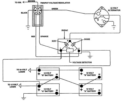
Prestolite 8rg3008 24 Volt Alternator Wiring Diagram, Hd ... PRESTOLITE 8RG3008 24 VOLT ALTERNATOR WIRING DIAGRAM PDF. Should the voltage raise or decrease drastically, the regulator will increase or decrease the output of the alternator to maintain a steady flow of voltage to the battery. Cooper Wiring 4409-BOX Armored Yellow 3 Wire 20 Amp 5 on Wiring Amp 5. We are promise you will like the 2290317527 ... How to Troubleshoot a 24-Volt Alternator Wire - It Still Runs Step 4. Follow the red, 24-volt cable from the positive battery terminal. It leads to the alternator and connects to the terminal labeled "B" or "Bat." Place the sensor on the end of the red wire from the multimeter onto the metal alternator terminal. If you have a two-wired alternator, place the metal sensor on the end of the black wire onto ... The John Deere 24 Volt Electrical System Explained The 24 Volt Electrical System. The electrical system used on John Deere diesel tractors with electric start is a 24 volt split load system. Basically there are 3 separate electrical systems within the one main system. 1. 24 volt starting system 2. 12 volt system controlling one side of the tractor 3. 12 volt system controlling the opposite side ...
24 volt alternator wiring diagram. Wiring Diagram 24 Volt Alternator - Wiring Diagram Line 24 volt alternator installation operation manual introduction 2h questions identifying a 24v vs 12v externally regulated ih8mud forum 3 wire regulator diagram ... PDF Bosch 24v Alternator Wiring Diagram Bosch alternator wiring diagram 24v 55amp type 24 volt installation d wire on my car s ... 12 Volt Alternator Wiring Diagram ¦ Wiring Diagram Wiring a Lucas alternator is a fairly straightforward process, but some car manufacturers do position alternators in hard to access places. Wiring Diagram How An Alternator Works - Wiring Diagram Wiring diagram how an alternator works. 12 volt alternator installation operation manual introduction thank you for choosing a balmarr high output alternator. The alternator has a rotor that spins when the engine cranks. Alternators that have one positive wire connected to the alternator has the ground connected to its case. › peugeot-fault-codesPEUGEOT Fault Codes DTC - Car PDF Manual, Wiring Diagram ... Hello nice to meet you I got problem with my R300 BT (Radio), and need R300 BT wiring diagram for opel astra K 2017 sport tourer to repair it, can you plaeas send the diagram or pins info from R300 BT wiring diagram opel. Thnx ikramidis@hotmail.com #159. Ghaly (Saturday, 12 September 2020 16:36)
24 v wiring - The Diesel Stop That might have fried the gen an reg. thanks for all your help I have a wiring diagram if anyone needs on for 3010,4010 24 volt system sure spins the starter alot better now. Mine : 1999 F-250SD supercab 4x4 7.3L ,airaid intake,5 in. exhaust, BTS Tranny , TS 6 POS. chip, 6inch lift, 35 inch Nitto Trail Grapplers H2E pro-comp traction bars ... › ldr-circuitLDR Circuit Diagram - Build Electronic Circuits Nov 01, 2013 · How The LDR Circuit Diagram Works. The LDR circuit diagram works like this: When it’s dark, the LDR has high resistance. This makes the voltage at the base of the transistor too low to turn the transistor ON. Therefore, no current will go from the collector to the emitter of the transistor. John Deere 3020 Diesel 24V Electrical ... - Green Tractor Talk Since the 24 volt system is actually two 12 volt systems joined together, the two circuit breakers at the starter were designed to protect the two circuits. I don't want to alarm you, but quite a few of the early 24 volt tractors burned up wiring harnesses due to the lack of these circuit breakers and fused ground lead. WIRING DIAGRAM 24 VOLT SYSTEM Caterpillar DIESEL WIRING DIAGRAM 24 VOLT SYSTEM Caterpillar DIESEL is a free worksheet for you. This wallpaper was uploaded at January 13, 2022 by tamble in Cat 5.. Here is one of the 24 Volt Alternator Wiring Diagram D5 Cat that you can use for your needs.
balmar.net › 2016/02/24V-Alternator-Manual24 -Volt Alternator Installation & Operation Manual Introduction Feb 24, 2016 · (tach) wire if needed and other necessary wiring. Connect alternator to Balmar regulator wiring harness as indicated in wiring diagram included on Page 12. The alternator’s positive and ground cables should be sized according to the chart on Page 3. 7. If a new regulator is being installed along with the alternator, complete its wiring ... 24 Volt Starter Wiring Diagram - Wirings Diagram February 17, 2019. · Wiring Diagram. by Hadir. 24 Volt Wiring Diagram - 24 volt alternator wiring diagram, 24 volt contactor wiring diagram, 24 volt relay wiring diagram, Every electric arrangement is made up of various unique components. Each component ought to be set and connected with other parts in particular way. 12 Volt Car Starter Wiring Diagram - U Wiring Accuspark wiring diagrams to help you understand 1929 a 6v 12v diagram ignition system basics matt dubanoski systems short course 9n key needed the cj2a page 12 volt alternator conversion farmall cub converting 3 typical car starting t x how wire motorcycle basic for ford 2n 8n read relay an electrical circuit vincent electrics please ballast ... daviescraig.com.au › thermatic-electric-fansDavies Craig Pty Ltd Thermatic Electric Fans The Davies, Craig Universal Fan Fitting Kit includes all parts necessary for mounting and wiring any 12- and 24-volt electric fans – all Davies, Craig Thermatic ® Fans and other electric fan models.
ME08
24 Volt Battery Wiring Diagram - Wiring Diagram Trolling Motor Wiring Diagram 12 Volt Inspirationa Trolling Motor - 24 Volt Battery Wiring Diagram. Wiring Diagram comes with numerous easy to stick to Wiring Diagram Instructions. It's intended to assist all of the average consumer in creating a proper system. These instructions will likely be easy to understand and implement.

Amazon.com: New 24 Volt Alternator for TCM with Isuzu Engines ...
Bosch Alternator Al9963sb Wiring Diagram - schematron.org Bosch Alternator Al9963sb Wiring Diagram. BOSCH. Bus Alternators. N. Alternator - Bosch IR/EF. 24 Volt, Amp, w/o Pulley Bosch , ALSB 12 Volt, Amp, 1-Wire. faulty repair, improper adjustment, installation, lubrication, or wiring, neglect, misuse; or is caused by failure of a part not supplied by alternator installation instrUCtions.
Understanding Alternators : How-To Library : VW Corrado World
24 Volt Alternator Wiring Diagram - Wiring Diagram Alternator Delco Remy Dra3553. 24 volt alternator installation 12v externally regulated leece neville 24v 175a j advanced regulator 3 wire diagram 9l1841 assembly 12 62 contents quick reference in an output test under load question on gm wiring system serial voltage regulation 101 with jd 4020 paginated for pdf qxd the old again d8k delco remy dra3553 to conversion boat 4n3986 group charging ...
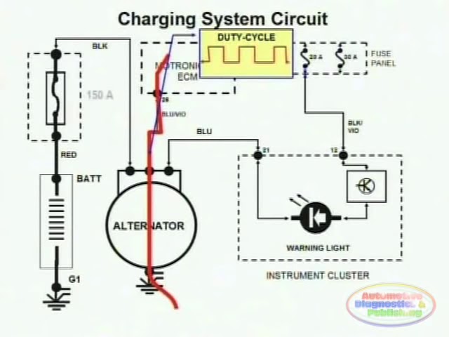
Charging System & Wiring Diagram - YouTube
Wiring diagram for 24 volt starter - Tractor Talk Forum ... Posted: Sat Jul 14, 2018 9:38 am Post subject: Re: Wiring diagram for 24 volt starter: My diagram shows the starter AND the negative side of the battery grounded to the frame/chassis. Unless you have an "isolated" ground alternator, the alternator is already grounded to the chassis thorough it's "frame", and keeping the 24 Volt system isolated from the chassis isn't possible.

12147N – WPS, Alternator – Bosch IR/EF 45 Amp/24 Volt, w/o ...
John Deere 4020 24v Wiring Diagram - schematron.org John Deere 4020 24v Wiring Diagram. John Deere 24v to 12v Conversion: I am going to start off this instructable ground and negative ground with an isolated 24v starting/charging system. both batteries. Does anyone have a wiring diagram for this. Re: JD 24v alternator wiring in reply to quake, The 24v JD system is not a true 24v system.
ELECTRICAL SYSTEM - TM-9-2320-303-10_29
JD 4020 24v alternator wiring - John Deere Forum ... Posted: Mon Jan 25, 2010 5:27 am Post subject: Re: JD 4020 24v alternator wiring. Tom43 On a 4020 24 volt system, the starter generator and regulator are NOT positive ground to the frame. The starter generator and regulator ALL have positive and negative connections and are isolated from the frame, thus they all have a "floating" ground.

Identify diagram: Alternator Wiring Pic2
Lucas Alternator Wiring Diagram Pdf - Irish Connections Elctrial Diagram For A Ford 3000 1970 Sel Lucas 5 Inch Starter Tractor Forum. Lucas 17acr alternator diagram 1969 mgc 16 acr 24 volt installation wiring mgb gt forum mg generator to conversion te20 and paginated for pdf qxd how the voltage regulator works electrical instruments by lotuselan net properly wire your marine 1971 tr6 5 switch a 2008 12 manual st series alternators instructions tvs ...
New 50 Amp 24 Volt Alternator Fits Delco 10Si 1 Wire Self Energizing Hookup
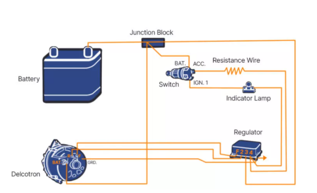
Alternator Voltage Regulation 101 (with Wiring Diagrams ... A typical 3-wire alternator wiring diagram with an internal voltage regulator. Computer-Controlled Voltage Regulation Many late-model vehicles use the engine computer, which is often referred to as the powertrain control module (PCM), to control alternator output.
24 -Volt Alternator Installation & Operation Manual ...
12 Volt Alternator Wiring Diagram - Wiring Diagram Alt Wire Diagram Alternator Wiring And Out The Dash Warning Light - 12 Volt Alternator Wiring Diagram. Wiring Diagram arrives with several easy to stick to Wiring Diagram Directions. It's supposed to assist all the typical user in developing a suitable method. These guidelines will likely be easy to grasp and apply.
WIRING DIAGRAM--24 Volt, 15 Ampere System 977H TRACK LOADER ...
Valeo Alternator Wiring Diagram Pdf - Wiring Diagram Line 24 Volt Alternator Installation Operation Manual Introduction. Instruction Sheet 10500196 24ap17 Cn02146 Rev8 33si 34si 35si 36si Alternator Installation Instructions Inc. Alpha Alternator. Valeo Alternator Diagram Wiring Manufacturers In Lulusoso Com Page 1. Jd Alternators Starter Motors Technical Manual Pdf Ctm77. A3375 Valeo Alternators.
Alternator Wiring Diagram: A Complete Tutorial | EdrawMax
› cgi-bin › viewitMF 135 updated wiring diagram? - Yesterday's Tractors With a wiring harness that has been worked on and repaired over the years the colors and wire sizes may not be right by the diagrams. The best one can do is use the diagram and volt/ohm meters to see if wires are connected between the correct points. Electricity doesn't care about the color wire one uses between points. You say you are in Canada.

4020 Rewire Help | Green Tractor Talk
1005047 Alternator Group Charging 24 Volt 50 Ampere ... 1005047 ALTERNATOR GROUP CHARGING 24 VOLT 50 AMPERE is a free worksheet for you. This wallpaper was uploaded at January 13, 2022 by tamble in . Here is one of the 24 Volt Alternator Wiring Diagram D5 Cat that you can use for your needs. You can also see other wiring diagram below.
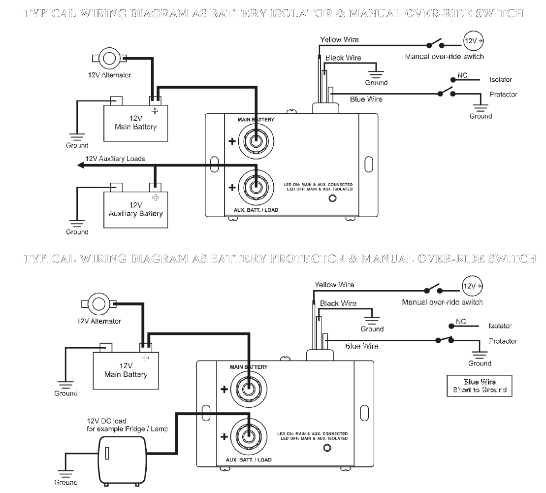
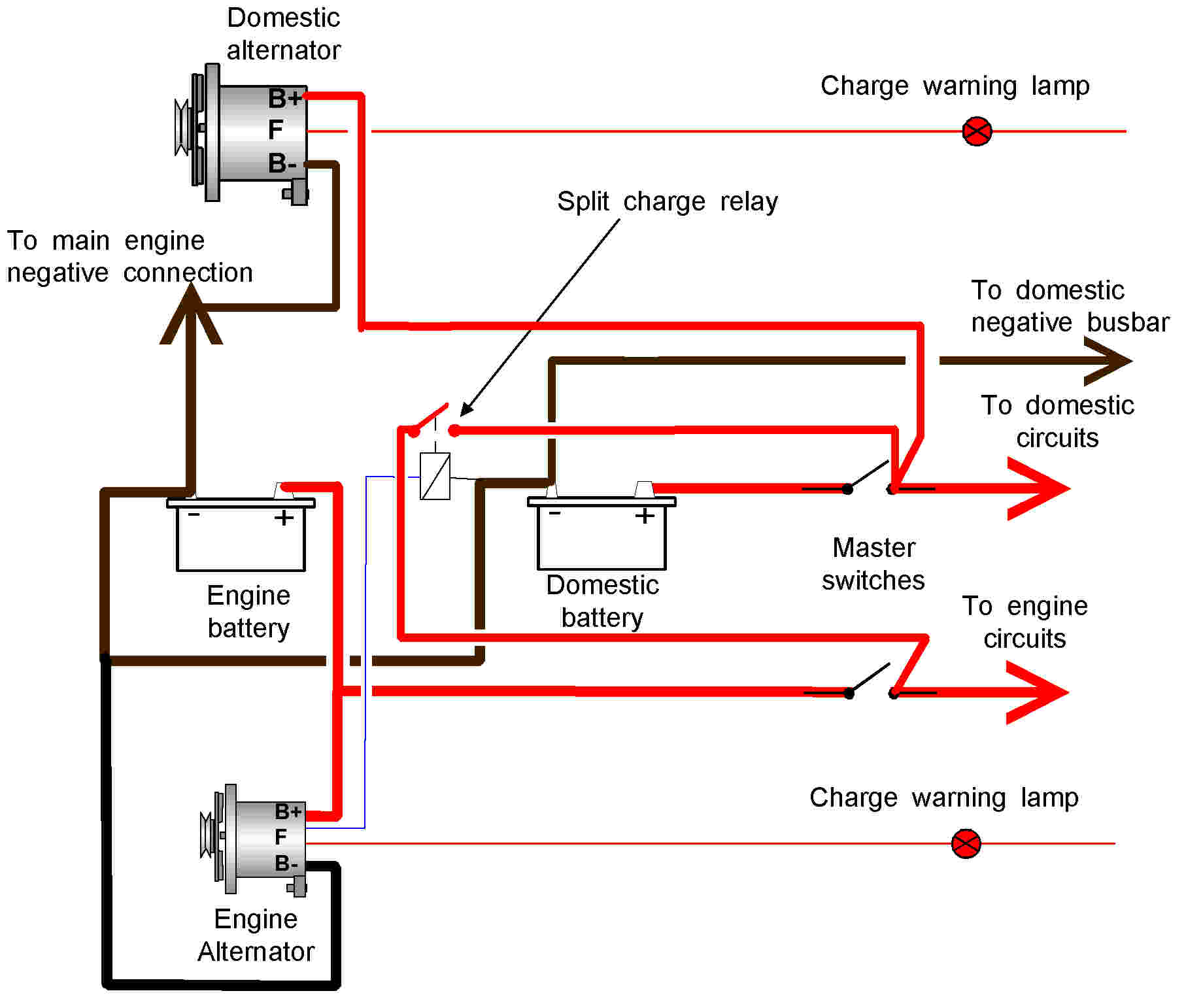
12 volt and 24 volt 80 amp DC battery isolator and split ...
24 Volt Wiring Diagram - Wirings Diagram 24 Volt Wiring Diagram - 24 volt alternator wiring diagram, 24 volt contactor wiring diagram, 24 volt relay wiring diagram, Every electric arrangement is made up of various unique components. Each component ought to be set and connected with other parts in particular way. If not, the structure will not function as it ought to be.
www.lrfaq.org: Land Rover FAQ: Series - electrics Series III ...
24v Dc Alternator Wiring Diagram - Wiring Diagram Alternator Voltage Regulation 101 With Wiring Diagrams In The Garage Carparts Com. 24 volt alternator installation 3 wire regulator diagram advanced self build adjule controler 12v externally regulated voltage regulation 101 with wiring my ih8mud forum battery combiner for victron lithium in an output test under load 15a dc charger by energy minn kota 100 amp to alpha 12 24v conversion boat ...

4N3986 ALTERNATOR GROUP-CHARGING (24-VOLT, 60-AMPERE)(24-VOLT ...
› 2020 › 04How to Wire a GFCI Circuit Breaker? 1, 2, 3 & 4 Poles GFCI Wiring This way, this 24 amp, 120V ordinary outlet is protected by the 30 amp GFCI circuit breaker. In case of 230V and 240V, the same wiring diagram should be follow expect only one line (L 1 or L 2) should be connected as hot to the input terminal of GFCI.
11-620 GoodAll Start-All 12 - 24 Volt Gasoline Engine Powered ...
The John Deere 24 Volt Electrical System Explained The 24 Volt Electrical System. The electrical system used on John Deere diesel tractors with electric start is a 24 volt split load system. Basically there are 3 separate electrical systems within the one main system. 1. 24 volt starting system 2. 12 volt system controlling one side of the tractor 3. 12 volt system controlling the opposite side ...
Alternator for Diesel Delco Style 27SI Series 24 Volt 80 Amp ...
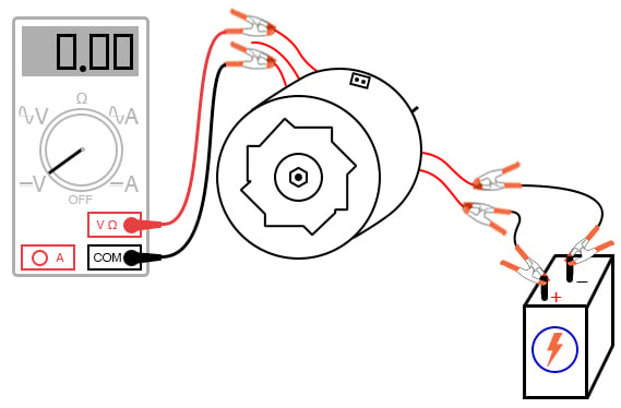
How to Troubleshoot a 24-Volt Alternator Wire - It Still Runs Step 4. Follow the red, 24-volt cable from the positive battery terminal. It leads to the alternator and connects to the terminal labeled "B" or "Bat." Place the sensor on the end of the red wire from the multimeter onto the metal alternator terminal. If you have a two-wired alternator, place the metal sensor on the end of the black wire onto ...

Balmar 621-VUP-24-70-DV Alternator and regulator kit -24 Volt 70 Amp Dual Pulley
Prestolite 8rg3008 24 Volt Alternator Wiring Diagram, Hd ... PRESTOLITE 8RG3008 24 VOLT ALTERNATOR WIRING DIAGRAM PDF. Should the voltage raise or decrease drastically, the regulator will increase or decrease the output of the alternator to maintain a steady flow of voltage to the battery. Cooper Wiring 4409-BOX Armored Yellow 3 Wire 20 Amp 5 on Wiring Amp 5. We are promise you will like the 2290317527 ...
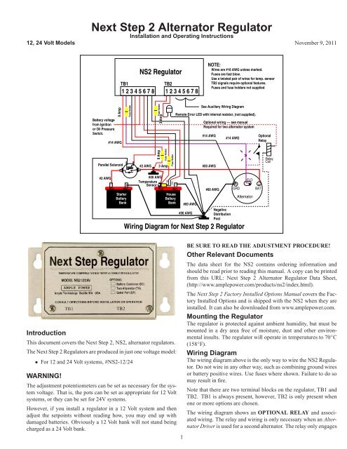
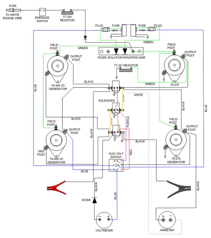
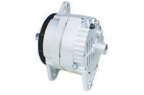
Next Step 2 Alternator Regulator - Ample Power

12V or 24V Alternator Open Circuit Protection Device

24V ALTERNATOR COMPATIBLE WITH JOHN DEERE LOGGER 2054 2554 3554 0-120-488-206 TY6774

Delco 10SI 12SI 15SI Alternator 24 Volt Voltage Regulator 1 Wire Self Exciting | eBay
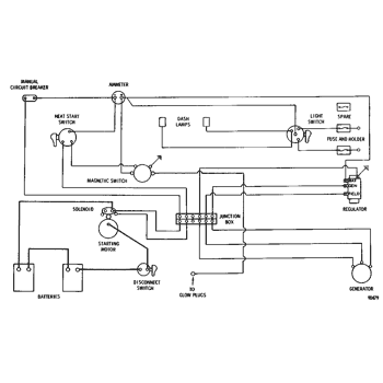
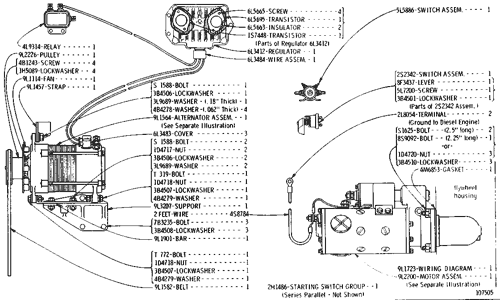
![ALTERNATOR AND STARTER WIRING [01E01] - TRACTOR John Deere ...](http://777parts.net/repository/600x/johndeere/ce/rp1285_________un01jan94.jpg)
ALTERNATOR AND STARTER WIRING [01E01] - TRACTOR John Deere ...
CONTENTS

ProReg-D 12 Volt / 24 Volt Advanced Alternator Regulator

Cushman Scooter Wiring Diagram On Cushman Truckster Wiring ...
paginated for pdf.qxd
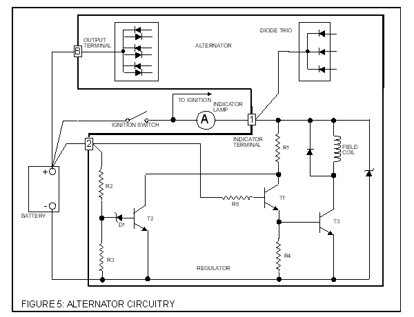
Automotive Alternator | AC Circuits | Electronics Textbook

Prestolite Leece Neville 24V 110A Brush Alternator-8LHA3096U
Alternator 12 to 24V conversion | Boat Design Net

Advanced Alternator Regulator
WIRING DIAGRAM--24 Volt System--Part 1 of 3 225 EXCAVATOR ...

Trollbridge24 Information

514-655102 - BOSCH TYPE ALTERNATOR 24VOLT 150AMP - Elreg

Balmar 94-Series Marine Alternator - Boundless Outfitters
9L1841 ALTERNATOR ASSEMBLY--12 Volt, 62 Ampere--End View ...
WIRING DIAGRAM--24 Volt System Serial No. 10K1 to 10K2404 ...
New and full of questions, 4020 electrical issues | Green ...
_web.jpg)
24-Volt, 1-Wire Alternator, 40 Amp, Isolated Ground
Comments
Post a Comment