43 rj31x wiring diagram
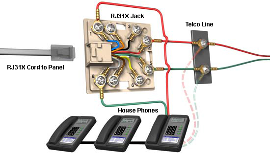
You Haven't Seen This RJ31x Jack Wiring & Use on Buzzfeed Wiring the Phone Input. The phone input (Line 1 - Blue pair) The input to the RJ31x jack comes from the phone line so you need the Blue pair to connect directly to the CAT 5 cable. Getting the input from the Arris Comcast modem requires the blue pair to connect into the RJ11 jack - pins 3 (R1 - BLU/WHT) & 4 (T1 - WHT/BLU). PDF Technical Bulletin: RJ-31X Telephone Jack Installation Wiring diagram 18 7 6 4 5 3 2 Ring (red) Tip (green) RJ-31X 8 pin modular connector To DACT Premises phones Black Yellow Surge protector No T-taps! It is our intention to keep application information current and accurate. We can not cover specific applications or anticipate all requirements. All specifications are
PDF Model XR500 Series Wiring Diagram AC Wiring must be in conduit and exit out the left side of the enclosure. ... Model XR500 Series Wiring Diagram Refer to XR500 Series Installation Guide (LT-0681 1.27) for a complete description of wiring connections. ... USOC RJ31X This unit complies with CFR 47 Part 68, FCC Rules as of date of manufacture.

Rj31x wiring diagram
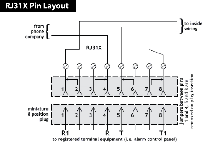
Rj31x Wiring Diagram - schematron.org The following diagram depicts the correct way to install the RJ31X jack. RJ31X Pin Layout (Fire Alarm and Security Wiring) The RJ31X jacks are designed to provide a fire or security alarm panel RJ31X Pin Layout Diagram. Wiring for telephone and data networks should be installed using standardized wiring . PDF Monitored Security System Installer's Guide - AlarmHow.net The wiring diagram for an RJ31X connector is shown below. The connections labeled R and T should be connected to the Tip & Ring connections coming into the house from the telephone company. You then connect the red and green that goes to all the phones in the house to T1 and R1. When the RJ31X plug is removed, the shorting bars connectsT1 to T Rj31x Wiring - Wiring Diagram Pictures - schematron.org Rj31x Wiring. Wiring Schemes. Wiring for telephone and data networks should be installed using . The RJ31X modular jack is the proper RJ to use for connecting alarm. RJ31X Pin Layout (Fire Alarm and Security Wiring). back to the list of pin layouts. The RJ31X jacks are designed to provide a fire or security alarm panel. Wiring Schemes.
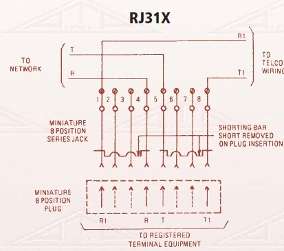
Rj31x wiring diagram. Rj 31X phone jack - Ask Me Help Desk Rj31X phone jack. This phone jack has 8 terminals The wiring diagram shows a wire jumping between 1 & 4 and another between 5 & 8. 4 is red and 5 isgreen.I assume that I would do that when I hook it up. I would like to just replace the existing 4 wire jack with this Rj31X jack. The phone plugs into the life line unitand the unit plugs into the ... Rj31x Jack Wiring Diagram The RJ31X Surface Mounting Jack with shorting bar is used with security systems or similar applications that feature a remote monitoring option. Below is the wiring diagram for your reference, the registered terminal equipment on this diagram is the security system.Rj31x Wiring Comcast - Wiring DiagramsRJ31X pin payout. Fire Alarm and Security ... Concord 4 Series Security Systems user guide - ADT Inc. installed RJ31X jack that is electrically in series and ahead of all other equipment attached to the same telephone line. Proper installation is depicted in the fol-lowing diagram. If you have any questions concerning these inst ructions, consult your local tele phone company or a qualified in staller about installing an RJ31X PDF RJ31X ADAPTER - Nortek Control RJ31X ADAPTER FOR USE WITH THE PERS CONSOLES installation instructions To provide proper telephone line seizure this cable must be connected to an 8-position telephone jack installed per FCC Universal Service Order Code RJ-31X or RJ-38X. See Figure 1 for details of the telephone jack wiring.
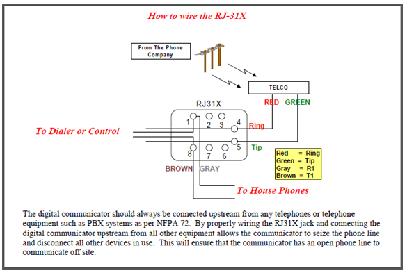
Rj31x Jack Wiring - Wiring Diagram Pictures - schematron.org Description An RJX jack is designed to facilitate wiring of an alarm panel and premise telephone on the same phone line while assuring that the processing of alarm signals has priority (line seizure) over a voice call. RJ31X Pin Layout (Fire Alarm and Security Wiring) back to the list of pin layouts. The RJ31X jacks are designed to provide a ... PDF 4010-9810 and -9816 DACTs (Digital Alarm Communication ... Refer to the 842-058 Field Wiring Diagram for additional wiring information. This publication discusses the following topics: Topic See Page # Overview 1 FCC and IC Requirements 2 4010-9810 DACT Card 5 ... RJ31X Jack RJ45 Connector (733-986) Pin 8 = TipH Pin 5 = Tip Pin 4 = Ring Pin 1 = RingH DACT Assy. 565-860 or 566-156 Rj31 Wiring Diagram - schematron.org Rj31 Wiring Diagram. RJ31X. OUT. IN. IN all diagrams = female jacks. NOTES: The term "RJ45" is . NOTE: MI and MIC leads are typically wired to an RJ36X series jack which can. This is how to connect the RJ31X jack in order to allow the alarm system to take over control of the phone line when it needs to dial. However, there was no seizing of ... Ademco Vista 20P Wiring Diagram - Home Security Systems ... Connect the flying leads of an RJ-31X cord to the terminals as shown. The Ademco Vista 20P diagram inside the lid indicates the standard colors for each screw terminal, making things easy. When wiring the RJ31X jack, be sure the pair of wires feeding phone line in to the jack goes to the red and green screw leads.
PDF Interlogix rj31x wiring diagram for use with telephone control module rj3tx jack telco protecror jack . wiring diagram for use with x.10 powerhouse burglar alarm interface module to control lights note: to the commandfr to control the lights: set input to b (dry contact closure) Honeywell VISTA 15P, 20P Programming Guide - Alarm Grid Good Day Marco, One question do you have the motion wired normally open or normally closed. If normally open the resistor goes parallel on the wiring. If normally closed the resistor goes in series thats one leg of the resistor on the wireing and one leg on the screw terminal on the motion. Leviton 8P8C RJ31X Surface Mount Jack with Shorting Bar ... 8P8C RJ31X Surface Mount Jack with Shorting Bar, Ivory. Questions & Answers . Hover Image to Zoom. share Share. print Print $ 4 96. Product Overview. The Leviton 40278-SBI is from the line of Leviton`s wallplates and housings. This model comes in ivory color. ... Unlike the Leviton 40249W wall plate, this wall plate's wiring type is 630-Amp ... Cat5 Phone Line Wiring Diagram - Studying Diagrams Rj31x Jack Wiring Diagram. It shows the components of the circuit as simplified shapes and the capacity and signal contacts between the devices. When using Cat5 use the center pair BlueBlue-white in the CAT5 cableConnect the CAT5 pair to the Red and Green on the standard phone jack.
Results page 138, about 'remote control circuit diagram ...
Rj31x Wiring Schematic - Wiring Diagram Pictures RJ31X Pin Layout (Fire Alarm and Security Wiring) The RJ31X jacks are designed to provide a fire or security alarm panel RJ31X Pin Layout Diagram. This is how to connect the RJ31X jack in order to allow the alarm system to take over control of the phone line when it needs to dial.Ademco Vista 20P Wiring Diagram.

LimeSDR Mini Ground-Station for Es'Hail-2 - GHz Europe
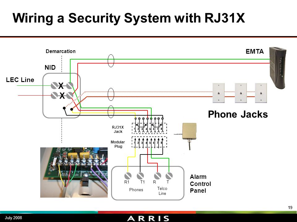
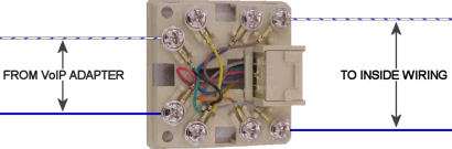
Comcast Phone Wiring There will already be a wire coming from the alarm system (the RJ31X jack) with two pairs being used, the orange pair, which feeds the phone jacks inside the home from the alarm (the yellow and black pair in this diagram), and the blue pair which carries dial tone to the alarm from the Network Interface Box (the red and green pair in this diagram).

10-Way RJ45 Telephone Module with RJ31X | Video and Voice ...
Rj31x Wiring Code, Industry Canada Electrical plan abbreviations ka24e engine wiring diagram 305 chevy engine wiring diagram f13 mic wire diagram 8 terminal rj31x wiring code 1995 dodge ram 1500 headlight wiring diagram 1986 chevy caprice fuse box 1996 geo. User interface a viewing port in the locked control panel enclosure door shows the system status light emitting diodes leds ...
RJ31X ADAPTER
Rj31x Jack Wiring Diagram - schematron.org Rj31x Jack Wiring - When wiring the RJ31X jack, be sure the pair of wires feeding phone line in to the jack goes to the red and green screw leads. The pair sending dial tone back to the premise phones should connect to the opposite pair of terminals. Add a telephone port quickly and easily with L-com's economical surface mount boxes.

DSC pc2550 v1-3 im eng 29000592 r2 by Sertek Servicios ...
Rj31x Wiring - Wiring Diagram Pictures - schematron.org Rj31x Wiring. Wiring Schemes. Wiring for telephone and data networks should be installed using . The RJ31X modular jack is the proper RJ to use for connecting alarm. RJ31X Pin Layout (Fire Alarm and Security Wiring). back to the list of pin layouts. The RJ31X jacks are designed to provide a fire or security alarm panel. Wiring Schemes.

How Do I Connect an Interlogix Simon XTi or XTi-5 to Phone ...
PDF Monitored Security System Installer's Guide - AlarmHow.net The wiring diagram for an RJ31X connector is shown below. The connections labeled R and T should be connected to the Tip & Ring connections coming into the house from the telephone company. You then connect the red and green that goes to all the phones in the house to T1 and R1. When the RJ31X plug is removed, the shorting bars connectsT1 to T

Alarm wiring at Telco Demarc
Rj31x Wiring Diagram - schematron.org The following diagram depicts the correct way to install the RJ31X jack. RJ31X Pin Layout (Fire Alarm and Security Wiring) The RJ31X jacks are designed to provide a fire or security alarm panel RJ31X Pin Layout Diagram. Wiring for telephone and data networks should be installed using standardized wiring .
Media Gateway Panel Module (S788) Functionality and ...

Rj31x wiring comcast diagram base website wiring comcast
RJ31X Jack 8P8C With Shorting Bar (RJ31X Interface) | NECABLES
09000 Cellular Alarm Transmission System User Manual T200 ...
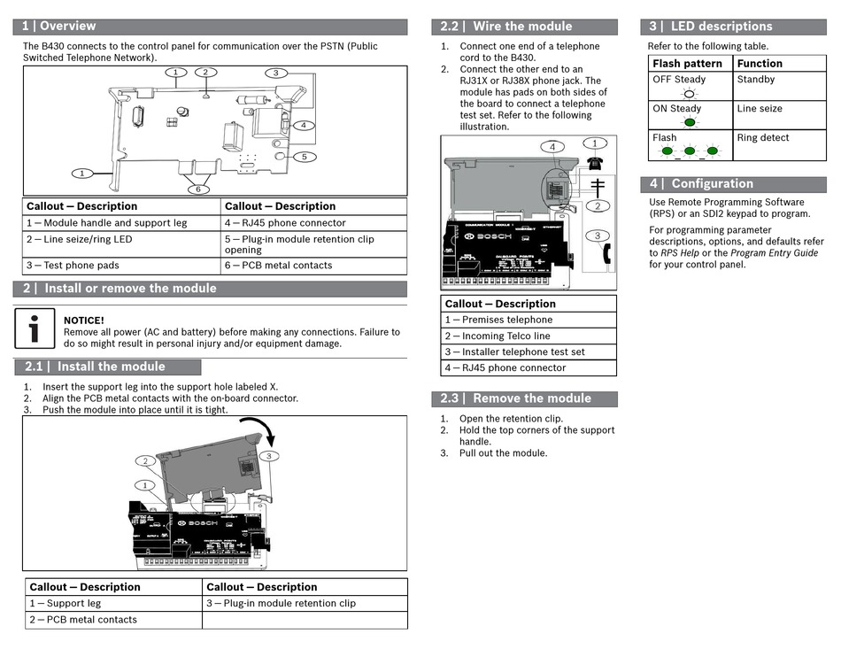
BOSCH B430 INSTALLATION MANUAL Pdf Download | ManualsLib
Line Seizure? What???
10BaseT - 100BaseT and other RJ-45 a Tutorial

RJ31X unplugged - YouTube
MC9420 US DECT HANDSET User Manual USERS MANUAL ARRIS Group, .

N7227V7ii Vista 10SE V7 Installation Manual

rear parking lights | Hot Rod Forum
General - Connecting A Line Seizure Jack

Amazon.com: ESM 1 RJ31X Phone Jack & Cord ADEMCO Vista GE ...
Uplink Remote Installation Guide

XT-30/50 Wiring Sheet - Vallance Security Systems

How to set up DSC pc1832 with OOMA? -Ooma Forums

My Images for David

How To Disconnect Smoke Alarm From Mains - unugtp

46 Wiring ideas | diy electrical, electronics basics, home ...

You Haven't Seen This RJ31x Jack Wiring & Use on Buzzfeed

Registered Jack – Things I Know
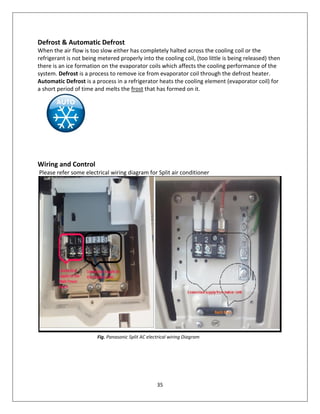
Basic refrigeration system & practice theory book
%2BMulti-Line%2BNetwork%2BInterface%2BUnit.png)
Electric Work: Phone wiring diagram, 1 - 8
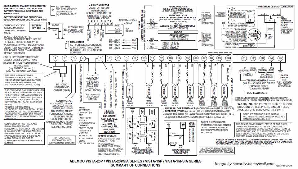
Ademco Vista 20P Wiring Diagram
RJ31X pin payout. Fire Alarm and Security Wiring
Telephony Troubleshooting in the Home - ppt video online download
RJ-31X - ECN Electrical Forums
Uplink Remote Installation Guide

You Haven't Seen This RJ31x Jack Wiring & Use on Buzzfeed
Construct Pro 1 x 6 Telephone Module with RJ31 Jack

I-7514U: ICP DAS USA : Active Hub Isolated 4 Channel Rs 485 ...

46 Wiring ideas | diy electrical, electronics basics, home ...

Shaxon UL133W-B, RJ31X Jack, RJ45 to Screw Terminals – White ...
How to Troubleshoot the D928
MediaMAXTM
How to Distribute VoIP Throughout a Home
Comments
Post a Comment