43 phase diagram of iron
What is the iron carbon phase diagram? - Wherevermag The iron-carbon phase diagram is widely used to understand the different phases of steel and cast iron. Both steel and cast iron are a mix of iron and carbon. This iron carbon phase diagram is plotted with the carbon concentrations by weight on the X-axis and the temperature scale on the Y-axis. Ellingham diagram - Wikipedia The direct reduction process for making iron rests firmly on the guidance of Ellingham diagrams, which show that hydrogen by itself can reduce iron oxides to the metal. Reducing agent for haematite. In iron ore smelting, haematite gets reduced at the top of the furnace, where temperature is in the range 600 – 700 °C. The Ellingham diagram ...
Phase diagram of the iron-cobalt system [6,7]. | Download ... Download scientific diagram | Phase diagram of the iron-cobalt system [6,7]. from publication: Article: The influence of iron content and powder metallurgy processing route on microstructure and ...

Phase diagram of iron
PDF Crystal structure and phase diagrams of iron-based ... Crystal structure and phase diagrams of iron-based superconductors Xigang Luo1,2 and Xianhui Chen1,2* Since the discovery of high-temperature superconductivity (HTS) in iron-based compounds, a variety of systems with dif-ferent spacer layers have been fabricated. Concurrently, consid-erable experimental and theoretical effort has been expended What is Phase Diagrams of Iron-carbon System - Definition ... Phase diagrams are graphical representations of the phases present in an alloy at different conditions of temperature, pressure, or chemical composition. Phase Diagram of Iron-carbon System The simplest ferrous alloys are known as steels and they consist of iron (Fe) alloyed with carbon (C) (about 0.1% to 1%, depending on type). PDF The iron-iron carbide (Fe-Fe3C) phase diagram Review Fe-C phase diagram • 2 important points-Eutectoid (B): γ⇒α+Fe 3C-Eutectic (A): L ⇒γ+Fe 3C Fe 3 C (cementite) 1600 1400 1200 1000 800 600 400 0 12 3 4 5 66.7 L γ (austenite) γ+L γ+Fe 3C α+Fe 3C α + γ L+Fe 3C δ (Fe) C o, wt% C 1148°C T(°C) α 727°C = Teutectoid A R S 4.30 Result: Pearlite = alternating layers of αand Fe ...
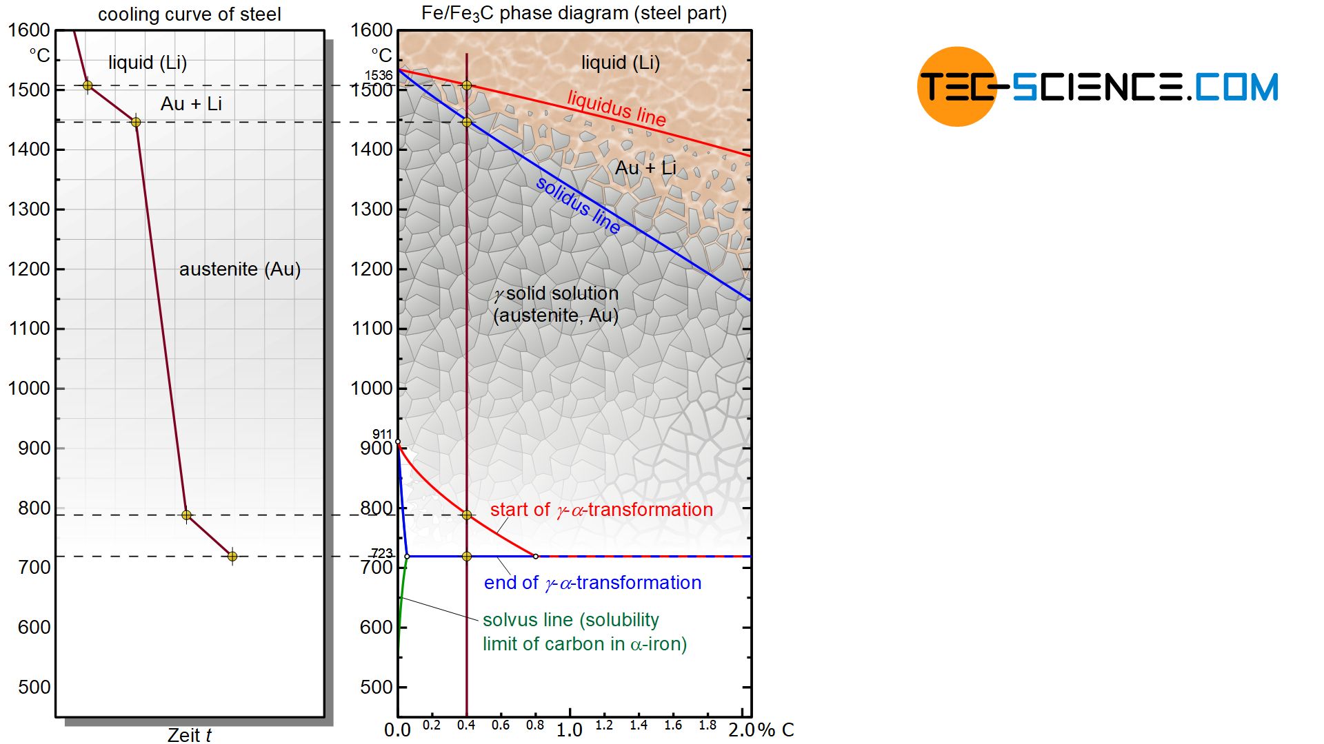
Phase diagram of iron. Phase diagram of the iron-copper system [16]. | Download ... Download scientific diagram | Phase diagram of the iron-copper system [16]. from publication: Microstructure refinement in Cu-Fe alloy using high pressure torsion | The effect of high pressure ... Iron-carbon phase diagram - Edelstahl härten Processed iron, such as steel and cast iron, always contains a proportion of carbon.This amount of carbon is decisive for the quality and properties of the steel. The iron-carbon phase diagram is an equilibrium diagram of the two elements. With its help, the relationship between the carbon content and the temperature is derived. Allotropes of iron - Wikipedia Low-pressure phase diagram of pure iron. BCC is body centered cubic and FCC is face-centered cubic. Iron-carbon eutectic phase diagram, showing various forms of Fe x C y substances. Iron allotropes, showing the differences in structure. The alpha iron (α-Fe) is a body-centered cubic (BCC) and the gamma iron (γ-Fe) is a face-centered cubic (FCC). Iron - Wikipedia Iron-carbon phase diagram. Types of steels and alloys. α-Iron is a fairly soft metal that can dissolve only a small concentration of carbon (no more than 0.021% by mass at 910 °C). Austenite (γ-iron) is similarly soft and metallic but can dissolve considerably more carbon (as much as 2.04% by mass at 1146 °C). This form of iron ...
PHASE DIAGRAM OF IRON-COBALT-SULFUR SYSTEM (Journal ... PHASE DIAGRAM OF IRON-COBALT-SULFUR SYSTEM (in Russian) Abstract A section of cobalt--iron--sulfur from quasi-binary FeS--Co/sub 4/Sub 3/ was studied using thermal, dilatometric, specific gravity, microhardness, and microstructure methods. Three surfaces of primary crystallization were revealed. PDF Chapter Outline: Phase Diagrams We will limit our discussion of phase diagrams of multi-component systems to binary alloys and will assume pressure to be constant at one atmosphere. Phase diagrams for materials with more than two components are complex and difficult to represent. An example of a phase diagram for a ternary alloy is shown for a fixed T and P below. PDF Chapter 9: Phase Diagrams - Florida International University Phase Diagrams • Indicate phases as function of T, Co, and P. • For this course:-binary systems: just 2 components.-independent variables: T and Co (P = 1 atm is almost always used). • Phase Diagram for Cu-Ni system Adapted from Fig. 9.3(a), Callister 7e. (Fig. 9.3(a) is adapted from Phase Diagrams of Binary Nickel Alloys , P. Nash PDF IRON CARBON PHASE DIAGRAM - Higher Technological Institute The Iron-Carbon Diagram: A map of the temperature at which different phase changes occur on very slow heating and cooling in relation to Carbon, is called Iron- Carbon Diagram. Iron- Carbon diagram shows - the type of alloys formed under very slow cooling, proper heat-treatment temperature and how the properties of steels and cast irons
Phase Diagrams of Iron-carbon System | nuclear-power.com Phase diagrams are graphical representations of the phases present in an alloy at different conditions of temperature, pressure, or chemical composition. Phase Diagram of Iron-carbon System The simplest ferrous alloys are known as steels and they consist of iron (Fe) alloyed with carbon (C) (about 0.1% to 1%, depending on type). Iron-Carbon Phase Diagram Explained [with Graphs] This iron carbon phase diagram is plotted with the carbon concentrations by weight on the X-axis and the temperature scale on the Y-axis. Iron crystal structures explained The carbon in iron is an interstitial impurity. The alloy may form a face centred cubic (FCC) lattice or a body centred cubic (BCC) lattice. 250+ TOP MCQs on Iron Carbon Phase Diagram and Answers Clarification: Binary phase diagrams are based on two component systems. Here, the two components may be mixed in an infinite number of different proportions, which indicates that composition also becomes a variable, along with pressure and temperature. Iron-carbon phase diagram, Pb-Sn diagram are the best examples of this category. 3. Iron Carbon Phase or Equilibrium Diagram or Iron Carbide ... Iron carbon phase diagram ferrite This solution has a melting point of 1538°C. Ferrite is the softest structure on the iron-iron carbide diagram. Ferrite acts magnetically at low temperatures, but its magnetic properties are dethatched once its temperature rises and above 786°C temperature it becomes non-magnetic.
Phase diagram for iron-platinum alloys. | Download Scientific ...
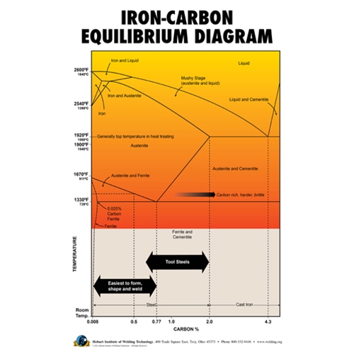
Iron-Carbon Diagram Explanation [PDF] - Mechanical E-Notes Iron-Carbon Phase Diagram with Detailed Explanation: If the percentage of the carbon is in the range of 0 to 2.11 % then it is called Steel and if the percentage of carbon is in the range of 2.11 to 6.67% then it is called Cast iron. As the carbon content increases, it produces more Iron-Carbide volume and that phase will exhibit high hardness.
Short Course Notes
Iron-Iron Carbide Phase Diagram | Material Engineering The Iron-Iron carbide (Fe-Fe 3 C) is defined by five individual phases and four invariant reactions. Five phases are- α-ferrite (BCC) Fe-C solid solution, γ-austenite (FCC) Fe-C solid solution, δ -ferrite (BCC) Fe-C solid solution, Fe 3 C (iron carbide) or cementite - an inter- metallic compound and liquid Fe-C solution.
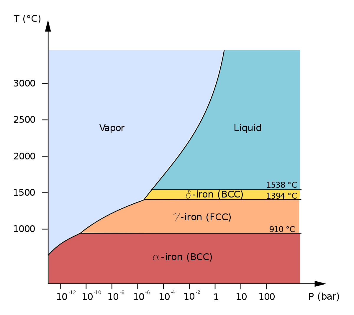
Allotropes of iron - Wikipedia
Phase Diagram - Industrial Metallurgists The phase diagram indicates that an iron-carbon alloy with 0.5% carbon held at 900 °C will consist of austenite, and that the same alloy held at 650 °C will consist of ferrite and cementite. Furthermore, the diagram indicates that as an alloy with 0.78% carbon is slow cooled from 900 °C, it will transform to ferrite and cementite at about ...
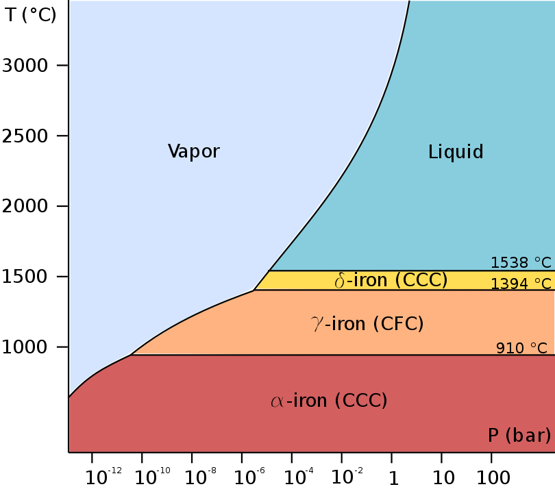
File:Pure iron phase diagram (EN).png - Wikimedia Commons
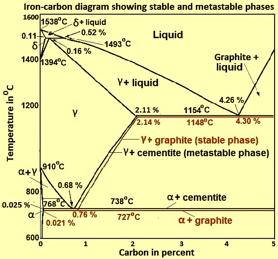
The Iron-Carbon Phase Diagram - IspatGuru The iron -carbon phase diagram in Fig 2 actually shows two diagrams namely (i) the stable iron-graphite diagram (red lines), (ii) and the metastable Fe-Fe3C diagram. Cementite is metastable, and the true equilibrium is to be between iron and graphite (C).
![Iron-Carbon Phase Diagram Explained [with Graphs]](https://fractory.com/wp-content/uploads/2020/03/Iron-carbon-phase-diagram-explained.jpg)
Iron-Carbon Phase Diagram Explained [with Graphs]
Phase diagram of iron, revised‐core temperatures - Ahrens ... Proposed phase diagram of iron. The 1573 K γ-phase values of the Hugoniot sound speed are consistent with phase diagrams of Boehler and Saxena et al.. The principal Hugoniot appears to cross the ε-(?) phase boundary at 200 GPa, and the (?)-liquid phase boundary at 243 GPa as proposed by Brown.
![Iron-carbon phase diagram [SubsTech]](http://www.substech.com/dokuwiki/lib/exe/fetch.php?w=&h=&cache=cache&media=iron-carbon_diagram.png)
Iron-carbon phase diagram [SubsTech]
Iron Phase Diagram - Roy Mech Solid Phases The phased diagram includes four solid phases α Ferrite ..The solid solution of carbon in iron. At 0% C this is pure iron. BCC crystal structure. The maximum solubility of carbon in iron is 0,02% at 723oC. The carbon atoms are located in the crystal interstices. Austenite The solid solution of carbon in γ iron is called austenite .
Solved 1. With respect to the iron-carbon phase diagram ...
Phase Diagram of Iron - SpringerLink Thus, when the reflection method is used, the parameters of a material under investigation are defined through the use of a double-compression Hugoniot or a decompression isentrope of iron. Particular difficulties arise when these processes lead to states in the field of phase changes of iron.
Fe (Iron) Binary Alloy Phase Diagrams
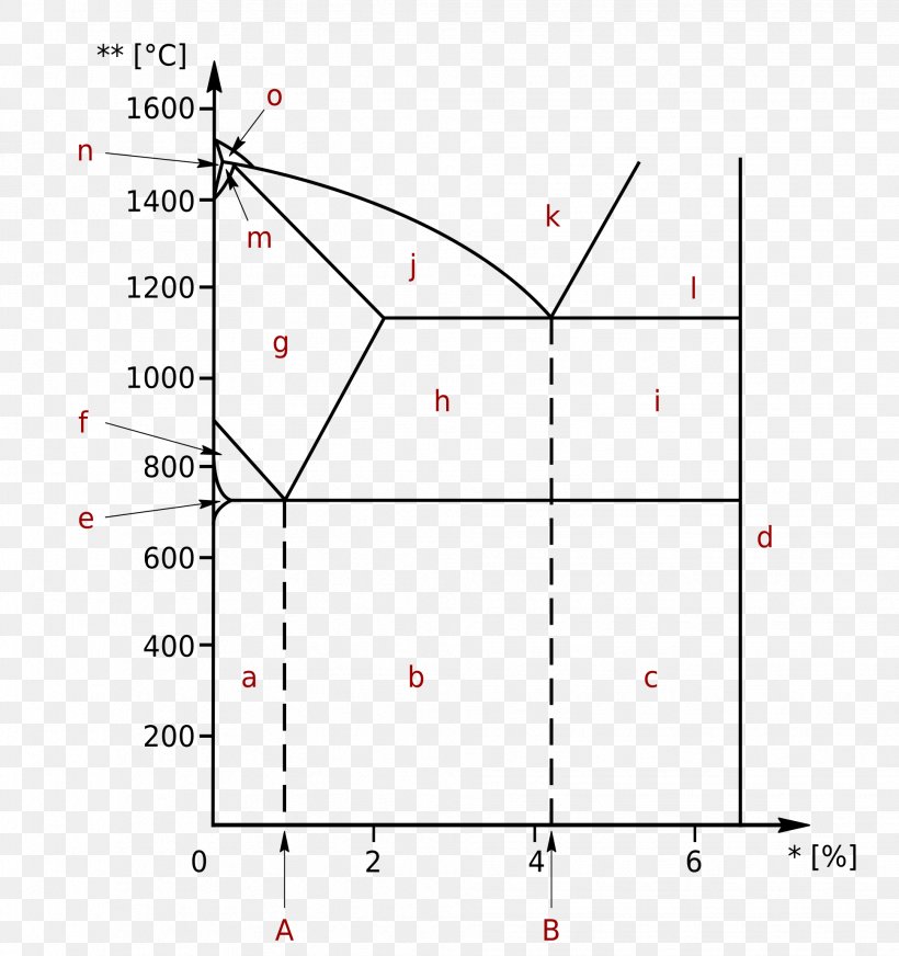
PDF The Iron Carbide (Fe Fe3C) Phase Diagram The Iron Carbide (Fe Fe3C) Phase Diagram The Iron ‐Iron Carbide (Fe‐Fe 3 C) Phase Diagram PeritecticL+ δ = γ at T=1493oC and 0.18wt%C Eutectic L = γ +Fe 3 C at T=1147oC and 4.3wt%C Eutectoid γ = α +Fe 3 C at T=727oC and 0.77wt%C Phases Present L Reactions

Sciencemadness Discussion Board - Iron-Iridium phase diagram ...
What is the Iron-Carbon Phase Diagram? - Engineering Choice The Fe - C diagram (also called the iron-carbon phase or equilibrium diagram) is a graphic representation of the respective microstructure states of the alloy iron-carbon (Fe-C) depending on temperature and carbon content. To explain this diagram, an introduction about metal structures and pure iron must be done.

Iron-carbon phase diagram |
File:Pure iron phase diagram (EN).svg - Wikimedia Commons Derivative works of this file: Pure iron phase diagram (EN).png This is a retouched picture , which means that it has been digitally altered from its original version. The original can be viewed here: Diagramma di fase del ferro puro.svg : .

File:Iron carbon phase diagram.svg - Wikimedia Commons
The Iron Carbon Phase Diagram The Iron Carbon Phase Diagram. There is more to the iron-carbon phase diagram than related in the backbone. In particular, there is some nomenclature that I avoided in the main text but that is important for understanding other writings about iron and steel. So let's start with a phase diagram that contains maximal information: A 1: The upper ...
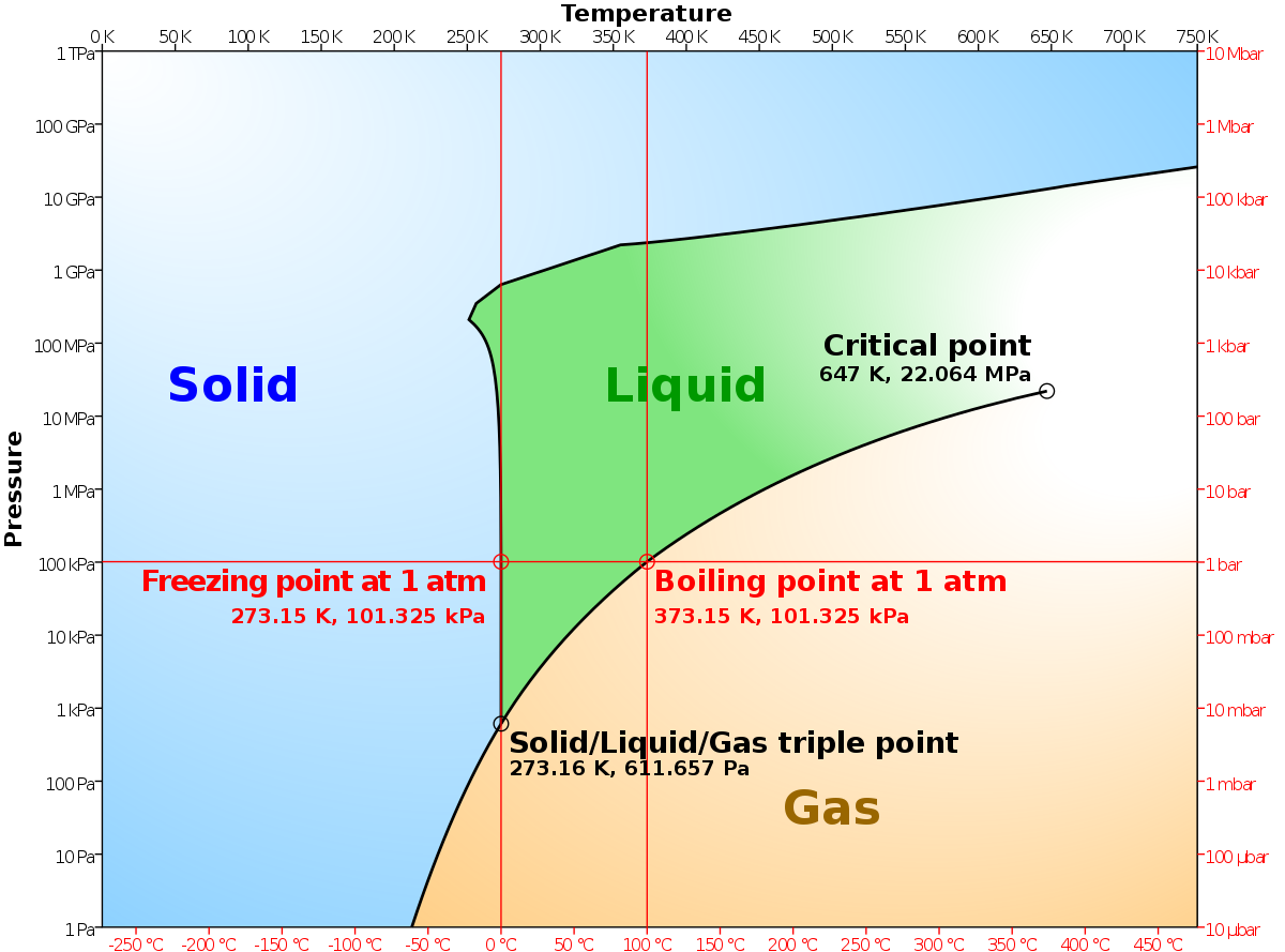
Solved The following figure is the phase diagram of pure ...
Iron Carbon Equilibrium Diagram with Explanation [Phase ... Nov 28, 2021 · The Iron carbon equilibrium diagram (also called the iron carbon phase diagram) is a graphic representation of the respective microstructure states of the alloy iron – carbon (Fe-C) depending on temperature and carbon content. The iron carbon phase diagram is commonly used to fully understand the various phases of steel and cast iron. Steel ...
Phase diagram of iron sulfide mineral simulated using the ...
PDF The iron-iron carbide (Fe-Fe3C) phase diagram Review Fe-C phase diagram • 2 important points-Eutectoid (B): γ⇒α+Fe 3C-Eutectic (A): L ⇒γ+Fe 3C Fe 3 C (cementite) 1600 1400 1200 1000 800 600 400 0 12 3 4 5 66.7 L γ (austenite) γ+L γ+Fe 3C α+Fe 3C α + γ L+Fe 3C δ (Fe) C o, wt% C 1148°C T(°C) α 727°C = Teutectoid A R S 4.30 Result: Pearlite = alternating layers of αand Fe ...
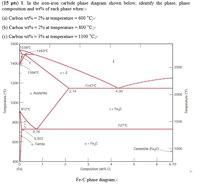
Solved (15 pts) 8. In the iron-iron carbide phase diagram ...
What is Phase Diagrams of Iron-carbon System - Definition ... Phase diagrams are graphical representations of the phases present in an alloy at different conditions of temperature, pressure, or chemical composition. Phase Diagram of Iron-carbon System The simplest ferrous alloys are known as steels and they consist of iron (Fe) alloyed with carbon (C) (about 0.1% to 1%, depending on type).
IRON CARBIDE EQUILIBRIUM DIAGRAM | Marine Inbox
PDF Crystal structure and phase diagrams of iron-based ... Crystal structure and phase diagrams of iron-based superconductors Xigang Luo1,2 and Xianhui Chen1,2* Since the discovery of high-temperature superconductivity (HTS) in iron-based compounds, a variety of systems with dif-ferent spacer layers have been fabricated. Concurrently, consid-erable experimental and theoretical effort has been expended
Iron-Manganese | Metallurgy for Dummies
Iron carbon phase

Can Someone Explain Me About This Iron - Carbon Phase Diagram ...
Cast irons
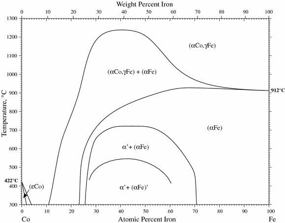
Co-Fe (Cobalt-Iron) | SpringerLink
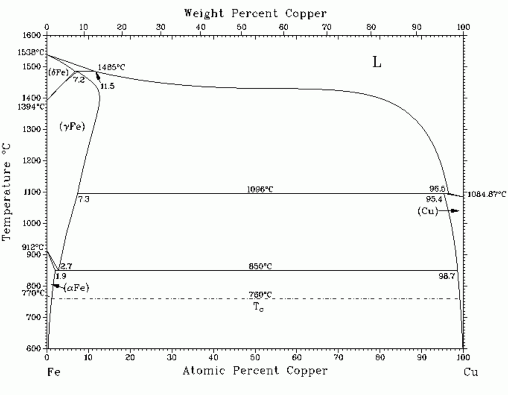
Solved Q1.1 (18 points) Refer to the iron-copper phase ...

Iron-carbon phase diagram - Edelstahl härten
Iron Phase Diagram - Roy Mech

Iron Carbon Phase song
The Iron-Carbon Phase Diagram – IspatGuru

Briefly explain the eutectic and eutectoid reactions in Iron ...

Stable and metastable phase diagram of iron-copper system ...
phase diagram iron carbon | Metallurgy for Dummies

File:Fe-W-phase-diagram.jpg - Wikiversity

Phase Diagram of Fe-P and Fe-N
What is the use of an iron carbide phase diagram? - Quora

The Iron Carbon Phase Diagram
Iron Phase Diagram - Roy Mech
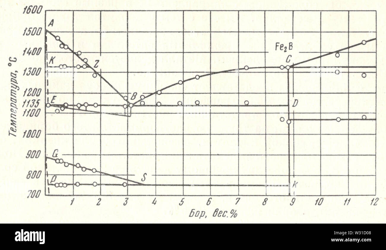
Phase diagram Boron Iron N P Tchizhevsky 1915 Stock Photo - Alamy
Iron-Carbon Equilibrium Diagram Poster

Hexaferrum - Wikipedia

Schematic of the phase diagram of pure iron at high pressures ...
Iron Carbon Phase or Equilibrium Diagram or Iron Carbide ...
Microstructure formation of steels during solidification ...

Iron-Carbon Equilibrium Phase Diagram (Gonzalez, 2008 ...
Phase diagram - Wikipedia

Iron-Titanium Phase diagram (Hirokai, 2000) According to Fig ...
Iron-Carbon Phase Diagram Cementite Triple Point, PNG ...
Comments
Post a Comment