43 control transformer wiring diagram
600v To 120v Transformer Wiring Diagram - easywiring Control transformer wiring diagram control diagram unique control power transformer wiring diagram motor. 600v to 120v transformer wiring diagram. Amps kva volts 1 732 x 1000 to calculate kva use this formula. Welcome to our site. Tutorial for wiring 480 240v primary for 240 120v secondary on epoxy resin encapsulated low voltage general purpose ... Mastering Motor Control Center (MCC): Wiring diagrams and ... Mastering Motor Control Center (MCC): Wiring diagrams and equipment from zero to hero. An MCC comprises three buses for a three-phase system and the cabinet consists of a circuit breaker, a motor starter, and a control transformer; however, the actual contents vary widely as per requirements. The circuit breaker has a handle that goes through ...
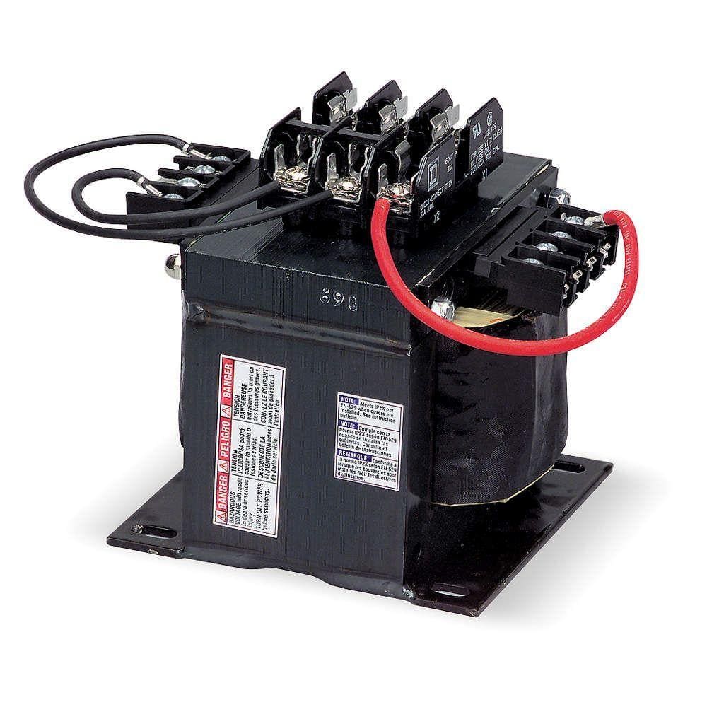
PDF Industrial Control Transformers - Sola/Hevi-Duty Sales The SBE Encapsulated industrial control transformers are epoxy encapsulated to seal the transformer windings against moisture, dirt and industrial contaminants. Extra deep, molded terminal barriers reduce the chance of electrical failure as the result of arcing or frayed lead wires. The rugged construction and proven reliability of
Control transformer wiring diagram
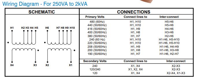
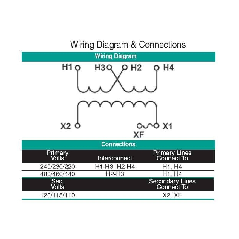
Dayton Control Transformer Wiring Diagram - IOT Wiring Diagram Control Power Transformer Wiring. Dayton control transformer 240v ac the part 1 open coil machine tool wiring diagrams encapsulated transformers 3w057 parts list and diagram micron b750btz13jkf class 2 120v acme electric ta tb series jefferson 631 circuit 4mtp8 trans in 208 240 480v out power 31eg97 50va daytonelectricchain manualzz practical machinist largest electricity 101 basic ... Wiring of control power transformer for motor control ... Figure 4 - Control power transformer wiring diagram The leads from the primary of the transformer are connected to L1 and L2 on the starter. In this way, the primary of the transformer is supplied with the same voltage as the power/motor circuit of the starter. PDF Acme Electric - Dry-Type Distribution Transformers ... GENERALELECTRICAL CONNECTION DIAGRAMSACME®TRANSFORMER™WIRING DIAGRAMS PRIMARY: 240 X 480 SECONDARY: 120/240 TAPS: None X4X1 H4 H3H2 H1 X2 X3 PRIMARY: 240 X 480 SECONDARY: 120/240 12, 2 /2% ANFC, 4, 21/2% BNFC X4 X1 H10 H2 H3 H1 X2 X3 H5 H6 H4 H7 H8 H9 Connect Connect Primary Primary Inter- Secondary Volts Lines To Connect Lines To
Control transformer wiring diagram. Lionel 1033 Transformer Wiring Diagram Lionel 1033 Transformer Wiring Diagram 'multi-Control transformer is SCHEMATIC WIRING DIAGRAM OF TRANSFORMERS Nos. Greenberg's Repair & Operating Manual For Lionel Trains. When you're wiring a Lionel transformer, you need to size the wires for safety and smooth running. PDF Mta Mtc Control Power Transformers CONTROL POWER TRANSFORMERS Industrial Control Transformers Table of Contents Description Page Numbering System ... Wiring Diagrams for MTE, MTG, MTK and CE Marked Transformers. . . . .9-24 Transformer Kits Include Fuses and Wiring Type MTE, MTG, MTA and MTC Transformers Control Transformer Wiring Diagram Download - Wiring ... control transformer wiring diagram - What is a Wiring Diagram? A wiring diagram is a simple visual representation with the physical connections and physical layout associated with an electrical system or circuit. It shows how a electrical wires are interconnected and may also show where fixtures and components may be connected to the system. Acme Transformer Wiring Diagrams - Studying Diagrams Square d transformer wiring diagram for control xfmr dry 1ph 25kva 240x480v 120. Interconnecting wire routes may be shown approximately where particular receptacles or fixtures must be on a common circuit. Obtaining from point A to direct.
Transformer Circuit Diagram - U Wiring Variety of electrical transformer wiring diagram. The circuit which demonstrates how to incorporate a transformer into a circuit is shown below. The voltage can be raised or lowered in a circuit but with a proportional increase or decrease in the current ratings. Micron Control Transformer Wiring Diagram Collection ... Please download these micron control transformer wiring diagram by using the download button, or right click on selected image, then use Save Image menu. Wiring diagrams help technicians to determine what sort of controls are wired to the system. Many people can read and understand schematics known as label or line diagrams. Wiring Diagram 110v Transformer - U Wiring Interconnecting wire routes may be shown approximately where particular receptacles or fixtures must be on a common circuit. Why use a Control Power Transformer. 12 Volt 10 Amp Transformer Battery Charger Circuit Diagram Youtube Battery Charger Circuit Circuit Diagram Battery Charger The schematic symbol for the transformer is represented by two groups the main motor […] PDF Industrial Control Wiring Guide - Weebly Part 5: Control circuit devices and switching elements. Part 6: Multiple function equipment such as that used for automatic emergency power switching. Part 7: Ancillary equipment such as terminal blocks used to connect copper conductors. Basically our control equipment panels should be built 2 is a more detailed guide to the requirements of 5
480v To 120v Control Transformer Wiring Diagram A wiring diagram is a streamlined standard pictorial depiction of an electrical circuit. ELECTRICAL DATA WIRING DIAGRAMS V, V V AC OR DC SINGLE PHASE L1 L2 One or more heaters in parallel, single phase. ACB L1 L2 V, V AC OR DC SINGLE /V TRANSFORMER ACB CONTROL CONTROL One or more heaters in parallel on V 3 phase circuit. 480v 3 Phase To 120 240v Transformer Wiring Diagram ... Wiring diagram 480 120v potential of control power transformer for basics information guide grounding transformers step up down and isolation 2019 3 phase 240 to n 0060 1021 230 vac ge catalog section 15 practical. 120 240v Transformer Wiring Diagram Diagrams 120 240 vac single split phase amp multi wire branch circuits marcus 120 240 volt ... 3 Phase Wiring Diagram - My Wiring Info Collection of 3 phase current transformer wiring diagram. I had to do this a few times with floodlights to be used outside. 3 Phase Motor Starter Wiring Diagram Pdf - Collections Of Motor Starter Wiring Diagram Pdf Image. The wiring diagram for connecting thee phase motor to the supply along with control wiring is shown in figure below. PDF Wiring Diagrams - AutomationDirect If you have any questions regarding these wiring diagrams or are having any difficulty correctly installing our transformers, please contact HPS customer service or technical support in the U.S. at 1-866-705-4684 or in Canada at 1-888-798-8882. HPS Imperator tm Industrial Control Transformer Wiring Diagrams Issue Date: October 2007 rev4 Page 1 of 9
GE Control Catalog - Section 15: Transformers
transformer wiring diagram - IOT Wiring Diagram Transformer Wiring Diagram. Single phase transformer connections the electricity forum control transformers power voltage stepdown converters how to wire a multi tap functional devices inc wiring diagram for cur with matching circuit scientific open coil machine tool 0 075 kva primary 240 x 480 secondary 120 federal pacific se2n f of ...

Wiring Acme industrial control transformer - DoItYourself.com ...
Single Phase Transformer Connections | The Electricity Forum A transformer wiring diagram can be found printed on the transformer nameplate or inside the cover to the wiring compartment. The leads or terminals are marked with Hs and Xs. In general, connecting individual transformers together requires that: Their voltage ratings must be equal. Their percent impedance must be equal.

Transferring From Schematic to Wiring Diagram for Connection ...
Control Transformer Wiring Diagram Gallery - Wiring Collection Control Transformer Wiring Diagram Gallery. Assortment of control transformer wiring diagram. A wiring diagram is a simplified traditional photographic representation of an electrical circuit. It shows the components of the circuit as simplified forms, and the power as well as signal links in between the tools. A wiring diagram usually offers information regarding the family…
Advanced transformers built for the industrial environment
PDF Electrical Connection Diagrams Acme Transformer Design Figures GENERALGENERALELECTRICAL CONNECTION DIAGRAMSACME®TRANSFORMER™WIRING DIAGRAMS PRIMARY: 240 X 480 SECONDARY: 120/240 TAPS: None X4X1 H4 H3 H2 H1 X2X3 PRIMARY: 240 X 480 SECONDARY: 120/240 2, 21/2% ANFC, 4, 2 /2% BNFC X4 X1 H10 H2 H3 H1 X2 X3 H5 H6 H4 H7 H8 H9 ConnectConnect Primary Primary Inter- Secondary Volts Lines To Connect Lines To

Buck boost transformer
PDF Transformers Section 14 Open Core and Coil Transformers ... 14-2 Control Catalog Transformers Open Core and Coil Transformers Section 14 Machine Tool Applications Single-Phase 60 Hz Terminal Board Connection Inrush VA @ .20 PF, Wiring Product List Price Input Voltage Output Voltage KVA Frame Size 95% Sec. Volt Diagram No.1 Number GO-80
Wiring of control power transformer for motor control ...
Industrial control transformers - Eaton 20 Apr 2017 — 1 See Page V7-T7-11 for wiring diagrams. 2 105°C insulation system. 3 Secondary fuse clips are not available on this catalog number.27 pages

Wiring Diagram of Starting Motor with Auto Transformer (4 ...
480 To 120/240 Transformer Wiring - Wiring Diagram Pictures Thread: input / output control transformer wiring mystery . single phase under 1 kva, x , / transformer in open style. Transformer To Wiring ImageResizerTool Com November 23rd, - to transformer wiring diagram as well as.GENERAL ELECTRICAL CONNECTION DIAGRAMSACME® TRANSFORMER™ WIRING DIAGRAMS PRIMARY: X SECONDARY: / TAPS: None X4X1 H4 H3H2 H1 ...
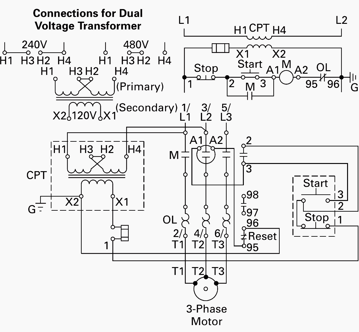
Correctly connect the dual-voltage control transformer cir ...
Impervitran Transformer Wiring Diagram ImperviTRAN™ By Micron Power Delivery Part Numbers/Wiring Diagrams. 3 -- 5 Selecting a transformer for industrial control circuit.How to Wire a Step-Down Transformer. A step-down transformer is one in which the primary voltage is higher than its secondary voltage. It is mainly designed to lower the voltage from the primary.

The Control Transformer (part 2)
PDF Control Transformers - Allied Electronics A control transformer is an isolation transformer designed to provide a high degree of secondary voltage stability (regulation) during a brief period of overload condition (also referred to as "inrush current"). Control transformers are also known as Machine Tool Transformers, Industrial Control Transformers or Control Power Transformers.

Manufactured by SNC, 350VA Control Transformer
ImperviTRAN Control Transformers - Wiring Diagrams - Galco CONNECTION DIAGRAMS. CONNECTION DIAGRAM: CONNECTION DIAGRAM: CONNECTION DIAGRAM: GROUP "A". GROUP "B". GROUP "C". CONNECTION DIAGRAM: CONNECTION DIAGRAM:.
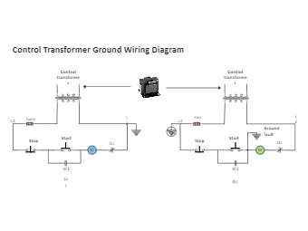
Control Transformer Ground Wiring Diagram | EdrawMax Editable ...
PDF Basic Wiring for Motor Contol - Eaton Two-Wire Control Two-Wire Control circuits — or Low Voltage Release One of the common control wiring circuits used is known as Two-Wire or Low Voltage Release (LVR). It utilizes a main-tained contact type of pilot device — such as a thermostat, float switch or presence sensor. Figure 6 shows the line and wiring schematics for this circuit.

Doorbell Wiring Diagrams- Do-it-yourself-help.com
480v To 120v Control Transformer Wiring Diagram - easywiring A wiring diagram is a simplified conventional pictorial representation of an electrical circuit. Diagrams Digramssample Diagramimages Dslr Nikon The schematic symbol for the transformer is represented by two groups the main motor circuit operates at v while the control circuit is at v. 480v to 120v control transformer wiring diagram.
Industrial control transformers
Industrial Control Transformers The control transformer line is particularly ... Single Phase Transformers ... 95 (3.75). 111 (4.375). 3.6 (7.9). 2. WEigHt kg (lbs). Wiring. DiAgrAm ...2 pages
Control Transformers, power transformers, voltage ...
PDF ImperviTRAN - Manufacturer of Industrial Control Transformers Part Numbers/Wiring Diagrams 16 -- 18 Product Dimensional Data - GlobalTRAN 18 -- 21 Product Selection Guide - Medium Voltage 22 Part Numbers/Dimensions Control Transformer Accessories 23 - 24 What is a Transformer 25 -- 26 Common Questions 27 - 28

Practical Machinist - Largest Manufacturing Technology Forum ...
PDF Acme Electric - Dry-Type Distribution Transformers ... GENERALELECTRICAL CONNECTION DIAGRAMSACME®TRANSFORMER™WIRING DIAGRAMS PRIMARY: 240 X 480 SECONDARY: 120/240 TAPS: None X4X1 H4 H3H2 H1 X2 X3 PRIMARY: 240 X 480 SECONDARY: 120/240 12, 2 /2% ANFC, 4, 21/2% BNFC X4 X1 H10 H2 H3 H1 X2 X3 H5 H6 H4 H7 H8 H9 Connect Connect Primary Primary Inter- Secondary Volts Lines To Connect Lines To
www.micronpower.com
Wiring of control power transformer for motor control ... Figure 4 - Control power transformer wiring diagram The leads from the primary of the transformer are connected to L1 and L2 on the starter. In this way, the primary of the transformer is supplied with the same voltage as the power/motor circuit of the starter.
GE Control Catalog - Section 15: Transformers
Dayton Control Transformer Wiring Diagram - IOT Wiring Diagram Control Power Transformer Wiring. Dayton control transformer 240v ac the part 1 open coil machine tool wiring diagrams encapsulated transformers 3w057 parts list and diagram micron b750btz13jkf class 2 120v acme electric ta tb series jefferson 631 circuit 4mtp8 trans in 208 240 480v out power 31eg97 50va daytonelectricchain manualzz practical machinist largest electricity 101 basic ...

The Control Transformer (part 1)

1000VA Industrial Control Transformer from SNC Mfg.

Wiring of control power transformer for motor control ...

Using Current Transformers with Current Sensing Relays

Autotransformer: What is it? (Definition, Theory & Diagram ...

Control Transformer 40VA, Primary 120, 208, 240V Secondary 24V, HVAC Furnace Multi Tap

Thermostat heat and cool 2 transformers | Thermostat wiring ...
Industrial control transformers
Control transformer hookup question. - Electric power ...
Industrial Control Transformer Wiring Diagrams
Industrial Control Wiring Diagrams

Buck boost transformer
Industrial Control Wiring Diagrams
50VA 240/480V X 120V 1PH

Buck boost transformer

Buck boost transformer
Using Potential Transformers - Continental Control Systems, LLC
Industrial Custom Control Transformer for High Voltage ...

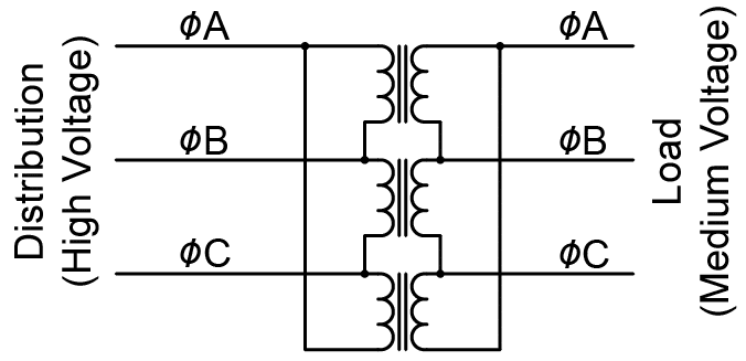
Three-phase Transformer Circuits | Polyphase AC Circuits ...

Using Potential Transformers - Continental Control Systems, LLC
GE Control Catalog - Section 15: Transformers

Multiple Winding Transformer and Multicoil Transformers

Wiring of control power transformer for motor control ...
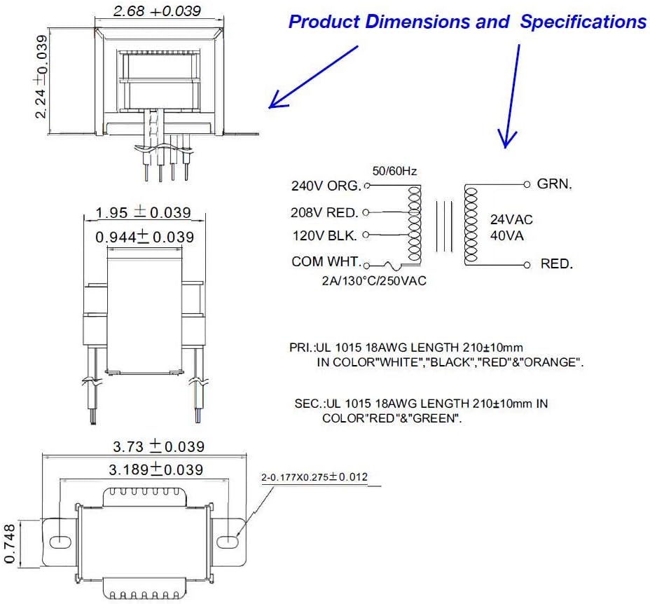
Endurance Pro Endurance Pro Control Transformer 40VA, Primary 120, 208, 240V Secondary 24V, HVAC Furnace Multi Tap, Jard 4031F, Packard 42440
Industrial Control Wiring Diagrams
GE Control Catalog - Section 15: Transformers
Comments
Post a Comment