42 micro switch diagram
Club Car Micro Switch Diagram - U Wiring Micro switch diagram gas club car. Club Car Parts Manuals. When the gas pedal micro switch goes bad it will not let the golf cart turn the motor over. Each part should be set and linked to different parts in specific way. As the name implies a microswitch is a small switch. It had been sitting up for a while. How to Wire up a Micro Switch - YouTube This video is aimed at anybody who is not very experienced with electronics and wants to know how to wire up a micro switch into their electrical system.
Micro Switch Wiring Diagram Fe290 See DIAGRAM Connect a Blue wire from the key switch to terminal 2 on the Golf/Street switch, and the Brown wire to terminal 1. May 18, · Connect them both to load on the micro switch. Wire you hot common/line/live , and neutral to micro. The micro is now acting as load for anything that was previously connected to the wall switch.

Micro switch diagram
Club Car DS Wiring Diagrams 1981 To 2002 - Golf Cart Tips 7. Accelerator micro switch failed. 8. Key Switch failed. 9. Neutral lock-out micro switch failed. STARTER-GENERATOR DOES NOT CHARGE BATTERY: 1. Loose or broken wire in starter-generator circ1 it. 2. Generator field coil shorted. 3. Brushes worn or commutator dirty. 4. Loose or slipping starter-generator belt. 5. Voltage regulator failed. 6 ... Push Button/Tactile Switch Pinout Connections, Uses ... Push Buttons are normally-open tactile switches. Push buttons allow us to power the circuit or make any particular connection only when we press the button. Simply, it makes the circuit connected when pressed and breaks when released. A push button is also used for triggering of the SCR by gate terminal. Ansul System Wiring Diagram - Wirings Diagram Ansul System Wiring Diagram - ansul fire suppression system wiring diagram, ansul system micro switch wiring diagram, ansul system wiring diagram, Every electrical structure consists of various different components. Each part should be set and linked to other parts in specific manner. If not, the structure will not work as it should be.
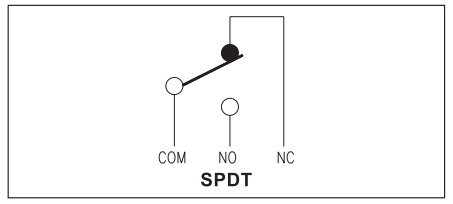
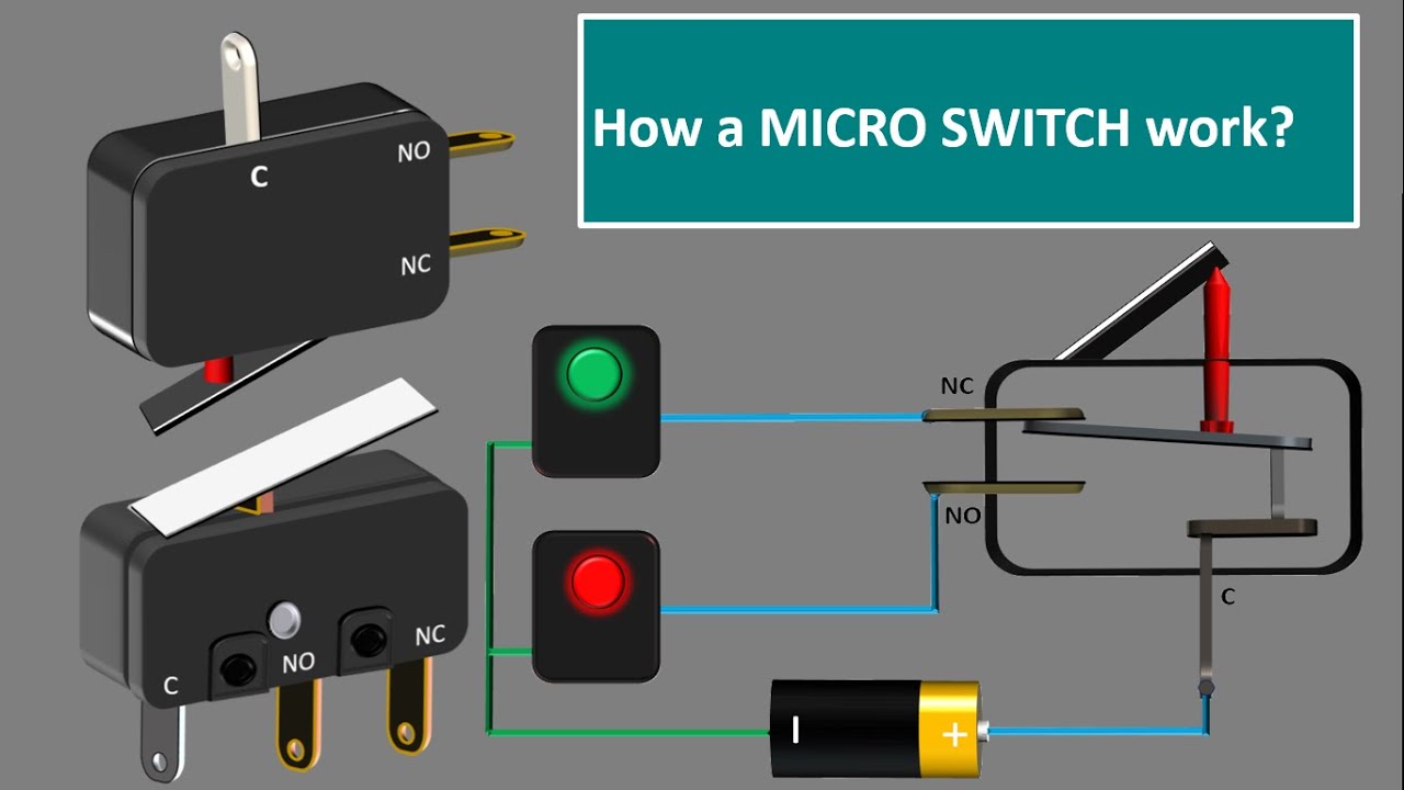
Micro switch diagram. PDF Air Curtain Micro Switch Installation Please purchase the door micro switch if not supplied with the product. Note: consult with your electrical professional for electrical connection. 1 : Wiring Diagram 2 : Connect the door micro switch into the Hot Line (L) wire of the power cord Is micro switch diagram correct? | Electrician Talk I've been seeing this wiring diagram for a microswitch... Now if the single pole switch were in the on position, and the micro switch is engaged connecting to the n.o. Wouldn't this cause the breaker feeding the exhaust to trip by feeding the single pole switch twice? Micro820 Wiring Diagram - schematron.org Description: The new wiring diagrams below show how to wire the Micro point controllers. The various Micro controller publications.Publication UMB-EN-E - March Wiring diagram for a 3-way switch, one of the many wiring diagrams showing different methods of wiring a three way switch circuit. EZGO Micro Switch Troubleshooting - Golf Storage Ideas EZGO Micro Switch Wiring Diagram As per the EZGO micro switch wiring diagram, there are four wires coming out of the main micro switch. The wires are divided using two individual spades. On one side, there is a white wire which connects to the ignition shutoff module and a black wire that connects to the key switch and also goes to the ground.
Ezgo Forward Reverse Switch Wiring Diagram - Wiring Diagram Ezgo Forward Reverse Switch Wiring Diagram. November 9, 2021 · Wiring Diagram. by Anna R. Higginbotham. ezgo forward reverse switch wiring diagram - You will want a comprehensive, expert, and easy to understand Wiring Diagram. With such an illustrative manual, you'll be capable of troubleshoot, avoid, and total your tasks with ease. Limit Switch Working Principle - your electrical guide Micro Limit Switch Another type of limit switch often used in different types of control circuits is the micro limit switch or microswitch. Micro limit switches are much smaller in size than an ordinary limit switch. This permits them to be used in small spaces that would not be accessible to the larger device. Diagnosistroubleshooting convertible top - Porsche 996 ... If the micro-switch is defective, replace the convertible-top latch. 196_98. If the convertible top is in the centre rear position (diagram) on opening, check the response of the micro-switch - not locked or locked (small diagram) - in the convertible-top latch. If the micro-switch is defective, replace the convertible-top latch. Example of How to Use a Micro Switch - Pinterest Aug 26, 2018 - Micro switch are switches that need very less amount of force (push/pressure) to operate and at rapid speed. Initially the contact of the ...
How Do You Wire A Micro Switch Diagram? - Google Groups What is a micro switch diagram? This is a diagram which displays the various components of a micro switch in order to help you know how it is wired. If you are using a micro switch for the first... Ansul Wiring Diagram Product Code. phase from control panel to fans (see wiring diagram.) - *1 or 3 Two Ansul micro switches are wired to control panel from fire system. Input power of . A new ansul system has been installed. The new system has two operating the microswitch. There is usually a wiring diagram with the unit.P ermit D rawings. Micro Switch Wiring Diagram Fe290 - schematron.org SWITCH DAMAGE • Wiring must be rated to meet or exceed circuitry MICRO SWITCH™ V-Basic Standard V15 ISSUE 3 CIRCUIT INFORMATION A circuit diagram is included on the switch case labeling each of the terminals. The normal position corresponds to the switch . Find great deals on eBay for club car micro switch. Club Car Forward Reverse Switch Wiring Diagram - Wirings ... Club Car Forward Reverse Switch Wiring Diagram - 1995 club car forward reverse switch wiring diagram, club car 36 volt forward reverse switch wiring diagram, club car ds forward reverse switch wiring diagram, Every electrical structure is made up of various unique components. Each part ought to be placed and connected with other parts in specific manner.
Example of How to Use a Micro Switch | Electronic circuit ...
Micro Switch Wiring - Here Are Facts You Should Know ... The diagram of a micro switch is similar to that of a circuit. There are 3 circles in such diagram. In between 2 of these circles, there is a line which runs through. The diagram below will explain more about this in details. The circle labelled A is usually called Common.

Understanding Micro Switches And Hysteresis | Avnet Abacus
Micro Switches | McMaster-Carr Open and close circuits quickly to minimize arcing and prevent contacts from sticking. These switches are often used as door-open indicators on appliances and enclosures or as an internal component in limit, pressure, and temperature switches.. Plastic covers (sold separately) are compatible with switches with screw terminals. They fit over the bottom of the switch to prevent contact with live ...
Détails sur EZGO Golf Cart Micro Switch Accelerator 94+ PDS/DCS ITS Pedal Box
A schematic diagram of the micro switch - ResearchGate ... micro switch is one of the most popular devices in the telecommunications field. The switch under study is made of L long doubly-clamped micro beam fixed to ...

China Cm1308 Micro Switch - China Micro Switch, Limit Switch
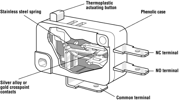
PDF Technical Explanation for Basic Switches - Omron switches for a specified movement and specified force enclosed in a case with an actuator provided on the exterior of the case. The following Basic Switch structure is shown as an example. Basic Switches are mainly comprised of five components. Structural Diagram of Typical Basic Switch Actuator Contact section Case Snap-action mechanism ...

a) A schematic of laminated micro-switch, (b) deflected ...
Micro Switch or Snap-action Switch - Components101 Description. Micro switch ZM and ZM1 Series are subminiature snap action switches from the Honeywell micro switch family of Z Series subminiature basic switches.; Although small in size, the ZM and ZM1 Series are rated for controlling electrical loads ranging from logic level (computer based circuits) to power duty switching (up to 16.1 A and 250 Vac).

Microswitch électrique NO NC 250V 16A à bouton 50g de force ...
Normally-open and Normally-closed Switch Contacts ... Electrical switches are always drawn in schematic diagrams in their "normal" statuses, regardless of their application. Normally-open and Normally-closed For instance, the following diagram shows a normally-open pushbutton switch controlling a lamp on a 120 volt AC circuit (the "hot" and "neutral" poles of the AC power source ...

Micro Switch Wiring – Here Are Facts You Should Know ...
PDF The Basics of Limit Switches - Eaton modular limit switches, are represented as their heavy duty application switch. This is due to the sensors having a long electrical and mechanical lifetime. These switches are designed so that the operating head, switch body and receptacle are separate components, as shown below. Convenience is the advantage of the plug-in modular design.
Microprecision - Microswitch MP110
Understanding a Microswitch - YouTube How a microswitch works

Mouse Micro Switch With Soldering Wire - Buy Soldering Cable ...
MICRO SWITCHES wiring diagram - All About Circuits 2,554. Feb 22, 2013. #3. The three terminals on a micro-switch should be marked as C, NC and NO. If they are not marked, it is easy to figure out using a meter. If you don't know how to do that, I wouldn't want to fly in the airplane you are working on. I know it sounds harsh, but it sure sounds like a major safety issue to modify cowl flaps on ...
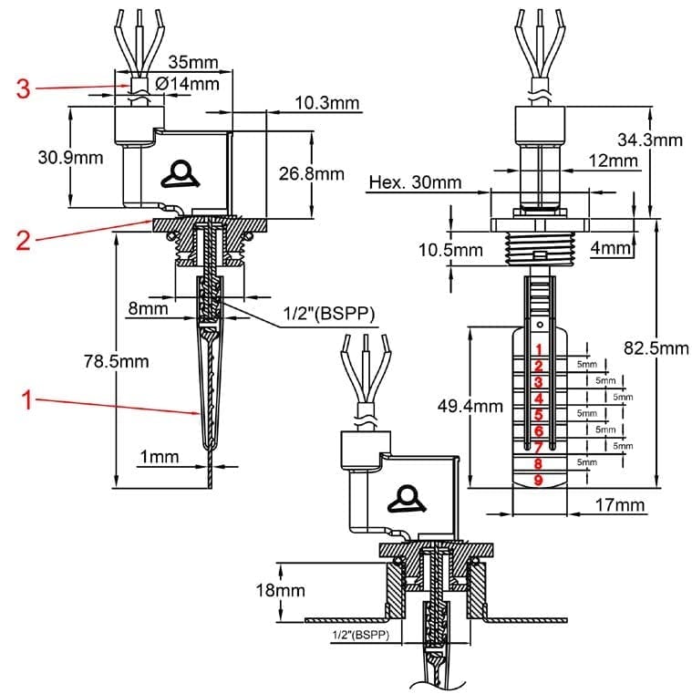
Paddle flow switches, micro-switch contact, 1/2” BSPP male thread
Micro switch: Working principle, types and applications A micro switch is a snap-action precision changeover switch with a very small contact gap. The snap-action defines a changeover switch whereby contact making ...

Multiple Limit Switches Problem - Programming Questions ...
How Do You Wire A Micro Switch Diagram? | Unionwell Switch What is a micro switch diagram? This is a diagram which displays the various components of a micro switch in order to help you know how it is wired. If you are using a micro switch for the first time, it is important to know how the components have been structured. This gives you a clue on how it can be wired to ensure proper functioning.
Is micro switch diagram correct? | Electrician Talk
40t125 Microswitch Diagram 3 Position 10A 250VAC 125V ... Toneluck S22AP00-D01 is a 40t125 microswitch with 3 position SPDT pcb terminals, and UL&ENEC certification of 10A 250VAC 125V, 50E4 cycles.
Micro switch contact à vis A poussoir long
Ansul Micro Switch Wiring Diagram - easywiring Ansul micro switch. B8f Xantrex Charge Controller Wiring Diagram Wiring Resources. Run a low voltage wire from the 12v micro switch in the ansul system to the 12v shunt trips. If an ANSUL fire system is present the fire system micro - switch will need to be wired to terminals as indicated on the installation diagram.

Commutateurs de proximité — Documentation FIRST Robotics ...
Ansul System Micro Switch Wiring Diagram - easywiring Ansul system micro switch wiring diagram. Each part should be set and linked to other parts in specific manner. They need periodic care. If not the structure will not work as it should be. Has a common NO and a NC Next route a black or red wire from a single pole volt breaker to the common wire in the Ansul micro switch box.
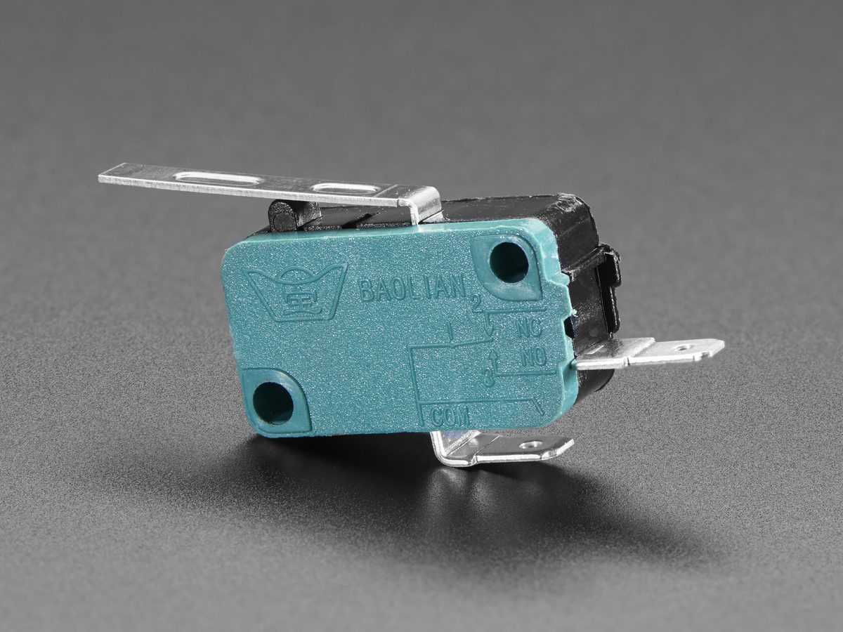
Adafruit 818 Micro Switch w/Lever - 2 Terminal Arduino ...
Ansul System Wiring Diagram - Wirings Diagram Ansul System Wiring Diagram - ansul fire suppression system wiring diagram, ansul system micro switch wiring diagram, ansul system wiring diagram, Every electrical structure consists of various different components. Each part should be set and linked to other parts in specific manner. If not, the structure will not work as it should be.
micro switch, switch limiteur , interrupteur ...
Push Button/Tactile Switch Pinout Connections, Uses ... Push Buttons are normally-open tactile switches. Push buttons allow us to power the circuit or make any particular connection only when we press the button. Simply, it makes the circuit connected when pressed and breaks when released. A push button is also used for triggering of the SCR by gate terminal.

Honeywell V15 SWITCHES MICRO SWITCH V-BASIC STANDARD Guide de ...
Club Car DS Wiring Diagrams 1981 To 2002 - Golf Cart Tips 7. Accelerator micro switch failed. 8. Key Switch failed. 9. Neutral lock-out micro switch failed. STARTER-GENERATOR DOES NOT CHARGE BATTERY: 1. Loose or broken wire in starter-generator circ1 it. 2. Generator field coil shorted. 3. Brushes worn or commutator dirty. 4. Loose or slipping starter-generator belt. 5. Voltage regulator failed. 6 ...

3 Pin Micro Switch

sourcing map XURUI autorisée 3Pcs Bouton Pression type micro ...

How to Wire up a Micro Switch

AZ-7120 Limit Switch
MS7 MICRO SWITCH Basic / Snap-Action Switches - Diptronics ...

33 idées de ArcadeJujuProject | bartop arcade, borne arcade ...

A schematic diagram of the micro switch | Download Scientific ...
MICROSWITCH - Définition et synonymes de microswitch dans le ...
Micro Switch Working. Micro Switch connection .snap Action Micro limit switch working Animation.

Limit Switch Working Principle - your electrical guide
Micro Switch Wiring Automobile Part Waterproof 12/24VDC ...

MICRO SWITCH™ Heavy-Duty Limit Switches Datasheet by ...

Micro switch: Working principle, types and applications

Limit Switches Explained - Working Principles & Types | RealPars

Micro-commutateur électrique 16A 250V T85 5E4 Kw1-103

100pcs Micro Limit Switches 16A 250V 125V NO+NC+COM 6.3mm 3 ...
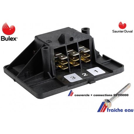
Couvercle pour clapet inverseur SAUNIER DUVAL et BULEX ...

V15T16-CZ100A06-K Microcommutateur SNAP ACTION avec levier ...

2CCP MICRO SWITCH Cable-Pull Safety Switches - Honeywell | Mouser
2340MK MICRO-SWITCH (CHERRY D48X/GREY)

1pc Saia-Burgess Micro Switch 2 Pin 26 (10) un 25E3 T85 ...

Microswitch pour RAZER Logitech G700 Mouse M18 | 10 pièces ...
How to Use an External Limit Switch with a Linear Actuator.

Single micro-switch controlling 3-phase motor. | Download ...

Micro Switch G2 user guide. : Aeotec Help Desk
Comments
Post a Comment