41 siemens motor starter wiring diagram
Siemens sirius soft starter wiring. - YouTube 4-minutes tutorial on how to wire Siemens sirius 3w3 softstarter. Part 1 - control by switch, part 2 - control by push buttons. Click the notification... siemens motor starter wiring schematic Datasheets Context Search Abstract: star delta wiring diagram motor start y catalog for 3RT series contactor* siemens SIEMENS SIMATIC NET PROFIBUS FC 6XV1 830-3EH10 siemens EN 60947 VDE 0660 IEC 947 induction motor soft starter 3 phase motor soft starter circuit 6ES7 134-4JB50-0AB0 ET200s F-CPU IM151-7.
PDF SINAMICS S120 Function Manual Siemens AG Automation and Drives Postfach 48 48 90327 NÜRNBERG GERMANY. • STARTER parameterization and commissioning tool • SINAMICS S120 Getting Started • SINAMICS Motors should be connected-up according to the circuit diagram provided. otherwise they can be destroyed.

Siemens motor starter wiring diagram
Starter Solenoid Wiring Diagram: 3 Pole Starter & What Wires Go To... A starter solenoid is an electromagnetic switch that connects and disconnects the battery to the starter motor assembly. It is a huge switch, which works as a bigger relay to turn It has three terminals on the back of the solenoid cap. If you want to know the starter solenoid wiring diagram in simple words. 60 Beautiful Motor Starter Wiring Diagram | Electrical circuit diagram... Apr 18, 2020 - 60 Beautiful Motor Starter Wiring Diagram- Your starter went out and you desire to replace it: Here's what to do:First you dependence to ac... 77 Lovely Direct Online Motor Starter Wiring Diagram. PDF MOTORS | 1/4 Siemens M 11 · 2003/2004 low-voltage MOTORS. Squirrel-Cage Motors Sizes 56 to 450 Output 0.06 kW to 1000 kW. Whatever your drive appli-cation is, motors from Siemens are sure to suit your drive system concept! - Wire-lattice pallet. 2/5, 2/47. Earth brushes for converter-fed operation.
Siemens motor starter wiring diagram. PDF 08_3211348_en_OM.pdf | WIRING DIAGRAM WIRING DIAGRAM. Components A6 CDI controller B1 Throttle position sensor B3 Wheel speed sensor E6 Thermoswitch (EXC-F SIX DAYS) G1 H15 Flasher indicator light H18 High beam indicator light K1 Starter relay with main fuse K2 Flasher relay L1 Pulse generator L2 Ignition coil M1 Starter motor N2... PDF Engine-mercruiser | wiring diagrams Starter motor. Water temperature. WIRING DIAGRAMS. i I E-,3-. 579. Engine-mercruiser 2S0 and 325 with water temperature switch. Ignition coil distributor. Wiring diagrams. Power trim with push button (early). PDF Wiring Diagram Book WIRING DIAGRAM A wiring diagram shows, as closely as possible, the actual location of all component parts of the device. This scheme is designed to prevent the unexpected starting of motors, which could result in injury to machine operators or damage to the driven machinery. SIMODRIVE AC Motors for Feed and Main Spindle Drives Planning... S The motor must be connected according to the circuit diagram supplied. S It is not permissible to directly connect the motor to the three-phase supply. The permissible cantilever forces are shown in the diagrams for the correspon-ding motors Application point of the cantilever forces at the shaft end.
Basic wiring for motor control - Technical data guide | EEP Wiring diagrams, sometimes called "main" or "construction" diagrams, show the actual connection points for the wires to the components and terminals of the controller. Basic wiring for motor control - Technical data. SIEMENS SIRIUS 3RM1 MANUAL Pdf Download | ManualsLib Siemens SIRIUS 3RM1 Manual. Load feeders and motor starters. Hide thumbs. Changes to the system configuration and wiring are only permissible in the voltage-free state. Connection of 3RM11 / 3RM13 Failsafe motor starters is only permissible when the power supply units (PELV and SELV)... PDF SINAMICS S120 Commissioning Manual · STARTER commissioning tool · SINAMICS S120 Getting Started · SINAMICS S120 Wiring example for parallel connection of Motor Modules in vector control mode. Drive line-up with two The following diagram shows the maximum number of controllable vector V/f drives with additional... PDF Basics of PLCs | Siemens PLCs S7-200 Siemens PLCs S7-200. Siemens makes several PLC product lines in the SIMATIC® S7 family. The left vertical line of a ladder logic diagram represents the power or energized conductor. In this example a motor started (M) is wired in series with a normally open momentary pushbutton (Start)...
Siemens Motor Starter Wiring Diagram - Wiring Schema Three Phase Dol Starter Wiring Diagram With Mccb Contactor. Https Encrypted Tbn0 Gstatic Com Images Q Tbn 3aand9gcq3k 5kcw2ve5chazf2gddfjlvt2xdkiaax9q Usqp Cau. Plc Program For Star Delta Motor Starter Diagrama De Circuito. Circuit Breaker Shunt Trip Wiring Diagram New Siemens... DOL Starter (Direct Online Starter): Wiring Diagram... | Electrical4U DOL Starter Wiring Diagram. 3 Phase Motor Starter with Overload Protection. A DOL starter (also known as a direct on line starter or across the line starter) is a method of starting a 3 phase induction motor. In a DOL Starter, an induction motor is connected directly across its 3-phase supply, and the... Typical Wiring Diagrams Siemens | PDF | Fuse (Electrical) Manual Motor Starting Switches AC 2-Speed Manual Motor Starting Switches. 8/138 Siemens Industry, Inc. Industrial Controls Catalog Reduced Voltage Starters & Pump Panels Class 36, 37, 88 Wiring Diagrams Auto Transformer. Siemens 3 Phase Motor Starter Wiring Diagram Siemens DOL Starter Control Wiring , Power Wiring , Ddiagram and Repair , 3 phase motor stater ELECTRICAL KNOWLEDGE ... Siemens DOL Starter / Power Wiring and Control Wiring of DOL Starter, Hello Friends Mai Deepak Sharma Ap Sab Ko Apne ...
Practical Machinist - Largest Manufacturing Technology Forum ...
PDF Manual Motor Starters, Controllers, and Protectors GV7 Wiring Diagrams. Manual Motor Starters, Controllers, and Protectors. Type GV2, GV3 and GV7. The direct rotary handle replaces the starter front cover and is secured by screws (see the diagram on page 21). It includes a device for locking the starter in the O (Off) position by a padlock.

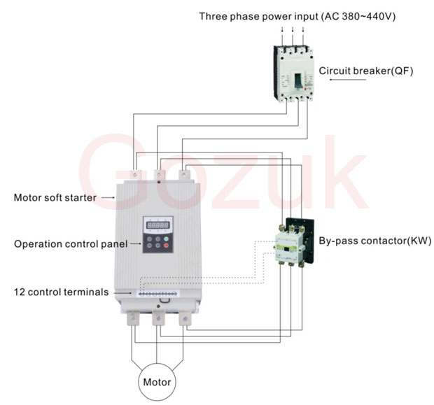
Electric Motor Starter S0 25a 15kw/500v 40° Ac 400-600v Ac/dc ...
PDF Microsoft Word - Contents eng.doc | Motor Data - The motor speed setpoint can be selected, using a digital setpoint, motorised potentiometer, fixed frequency, analogue input or via the serial link. - Mixed mode control is also available, allowing drive control and setpoint input to be from different sources. - A DC injection brake is incorporated, allowing...

Siemens 14DUE32BA | Motor Starter | Shop Dreisilker
PDF GI-2.0: Typical Wiring Diagrams | Bulletin 609 Manual Starters Wiring Diagram Symbols. Some Common and Important Terms. Bulletin 600 Manual Single Phase Starters. Internal wiring of these starters provides the necessary connections for interchanging two motor connections in the case of the 609RS or switching to another winding in the case of the 609TS.

22EUE32AA | Siemens 15 hp DOL Starter, 575 V, 3 Phase | RS ...
Siemens Motor Starter Wiring Diagram - Wiring Site Resource Magnetic Starter Wiring Wiring Schematic Diagram. Dol motor starter with 230v contactor coil. Siemens motor control center wiring diagrams at your fingertips within seconds. L1 to l1 1 l2 to l2 3 t2 of the ol relay back to l3 of the contactor 5 motor connections to t1 and t3 of the ol relay.
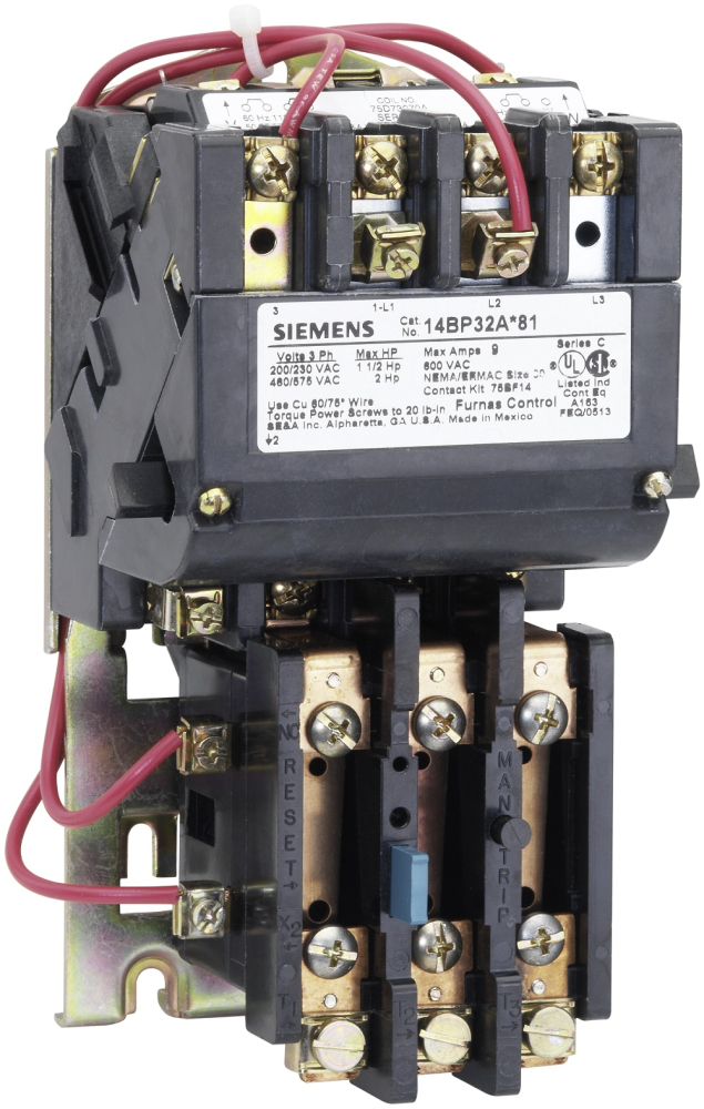
Siemens (Furnas), 14GP32AC81, 3PH, 60 Amps, Nema Motor Starter
PDF Manual SIRIUS 3RM1 Motor Starter | siemens.com SIRIUS 3RM1 Motor Starter Manual. Edition 06/2016. siemens.com. For wiring finely-stranded or stranded conductors without end sleeves on push-in connections, a screwdriver (with 3.0 x 0.5 mm blade) is required. Connect the motor as specified in the typical circuit diagrams.

60 Beautiful Motor Starter Wiring Diagram | Electrical ...
PDF MOTORS | 1/4 Siemens M 11 · 2003/2004 low-voltage MOTORS. Squirrel-Cage Motors Sizes 56 to 450 Output 0.06 kW to 1000 kW. Whatever your drive appli-cation is, motors from Siemens are sure to suit your drive system concept! - Wire-lattice pallet. 2/5, 2/47. Earth brushes for converter-fed operation.
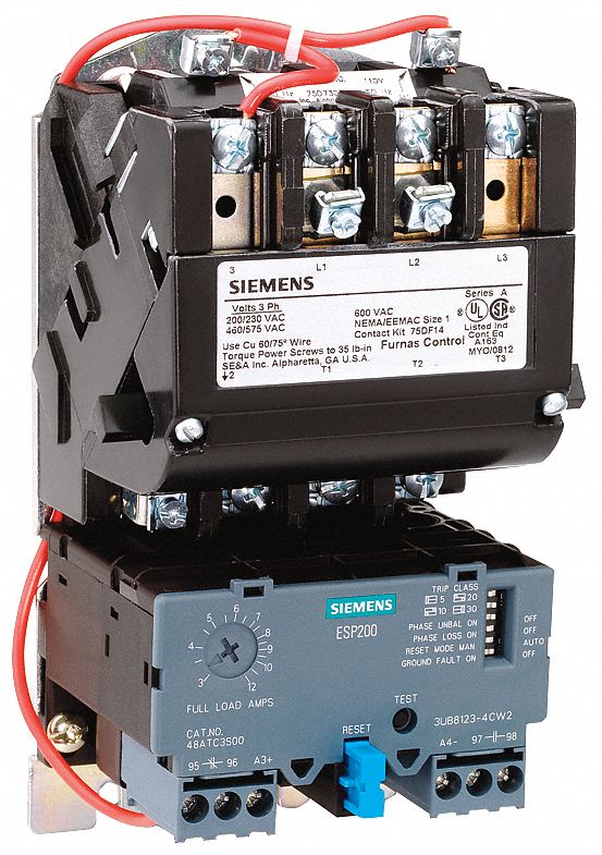
NEMA Magnetic Motor Starter, 480V AC Coil Volts, Overload Relay Amp Setting: 5.50 to 22A
60 Beautiful Motor Starter Wiring Diagram | Electrical circuit diagram... Apr 18, 2020 - 60 Beautiful Motor Starter Wiring Diagram- Your starter went out and you desire to replace it: Here's what to do:First you dependence to ac... 77 Lovely Direct Online Motor Starter Wiring Diagram.

Seimens Panel Board | KB Engineering
Starter Solenoid Wiring Diagram: 3 Pole Starter & What Wires Go To... A starter solenoid is an electromagnetic switch that connects and disconnects the battery to the starter motor assembly. It is a huge switch, which works as a bigger relay to turn It has three terminals on the back of the solenoid cap. If you want to know the starter solenoid wiring diagram in simple words.

PLC Program for Star Delta Motor Starter | PLC Motor Ladder ...
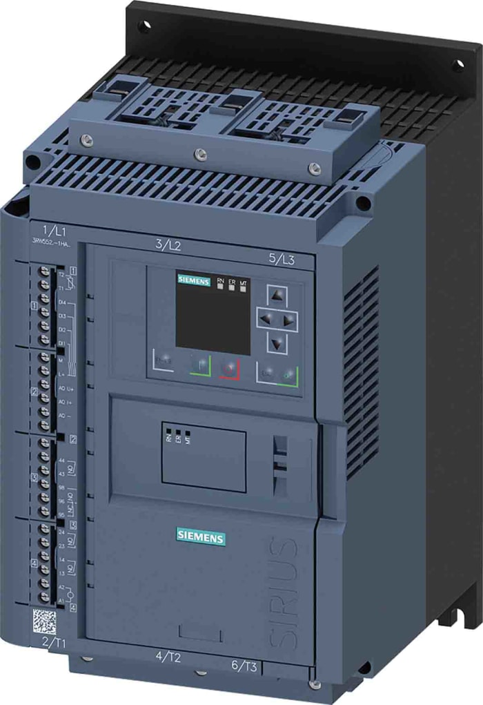
3RW5526-1HA16 Siemens | Siemens 75 kW Motor Starter, 77 A ...

PLC Siemens S7-1200 - 3-Phase Motor Starter - Star-Delta v.2 | Facebook

Heavy Duty Motor Starters - Siemens Pages 1-13 - Flip PDF ...
Direct On Line (DOL) Motor Starter
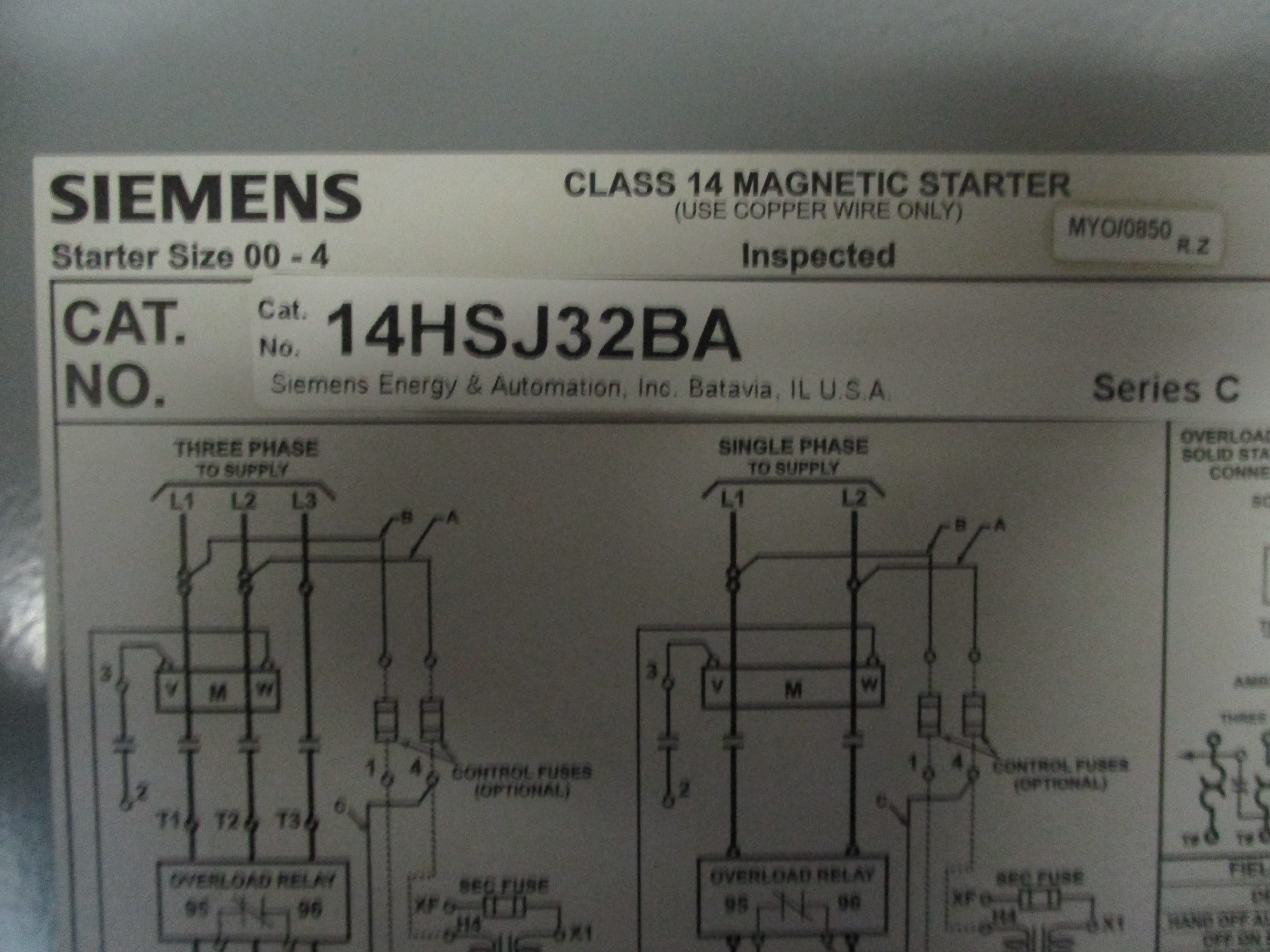
Siemens Magnetic Starter 14HSJ32BA Class 14 w/NEMA 3 Starter ...

SIEMENS 3RW4445-6BC34 AC Schleifscheibe Motor Sirius Weich ...

Siemens soft starter 3RW44 typical circuit diagram
need help with siemens 14DS32A | Electrician Talk
Soft starter wiring
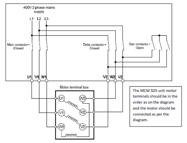
Star Delta Starters Explained - The Engineering Mindset

Single Phase Starter Connections. | Circuit diagram, Diagram ...

Motor Starter Wiring Diagrams - VintageMachinery.org ...

Siemens air circuit breaker 3WT wiring diagram and glossary
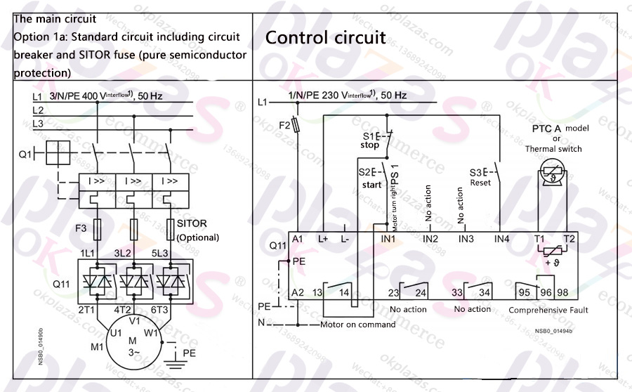
Siemens soft starter 3RW44 typical circuit diagram
Siemens 14CUC32BA Class 14 Full Voltage Non-Reversing Motor Starter, 110 to 120/220 to 240 VAC Coil, 3-Poles
Siemens 14CUA32AA 14CUA32AA SIE | Crum Electric Supply, Co.

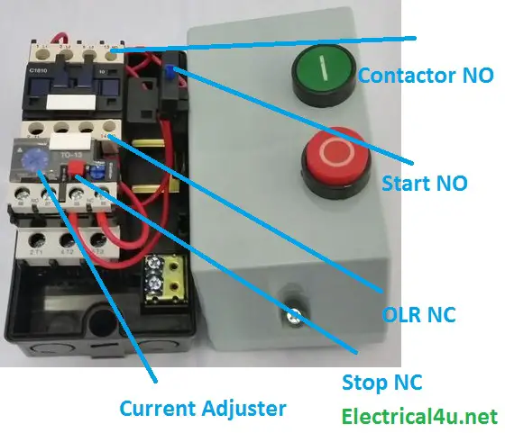
How to wire a contactor and overload - Direct Online Starter ...

Electric Motor Starter 22.5mm 3a 1.1kw/400v 200-400v/uc 24 ...
Direct On Line (DOL) Motor Starter
DOL Starter | Direct Online Starter Diagram, Construction ...
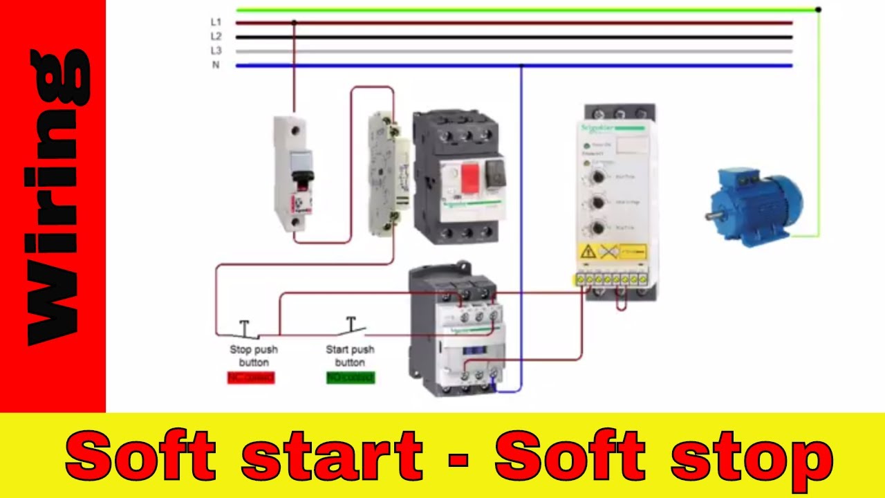
Siemens sirius soft starter wiring. - YouTube

DOL Starter Control Wiring | Direct Online Starter Circuit Connection By Electric Guru

3ph 415v 3.8amp 3 Ph Dol Starter 2 Hp Siemens, Model Name ...
Siemens – Starters – Deekay Electricals

Practical Machinist - Largest Manufacturing Technology Forum ...
2014 Product Catalog

3 Phase Contactor Wiring Diagram Pdf | Home electrical wiring ...
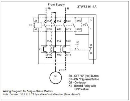
DOL Starter 3TW7291-1A
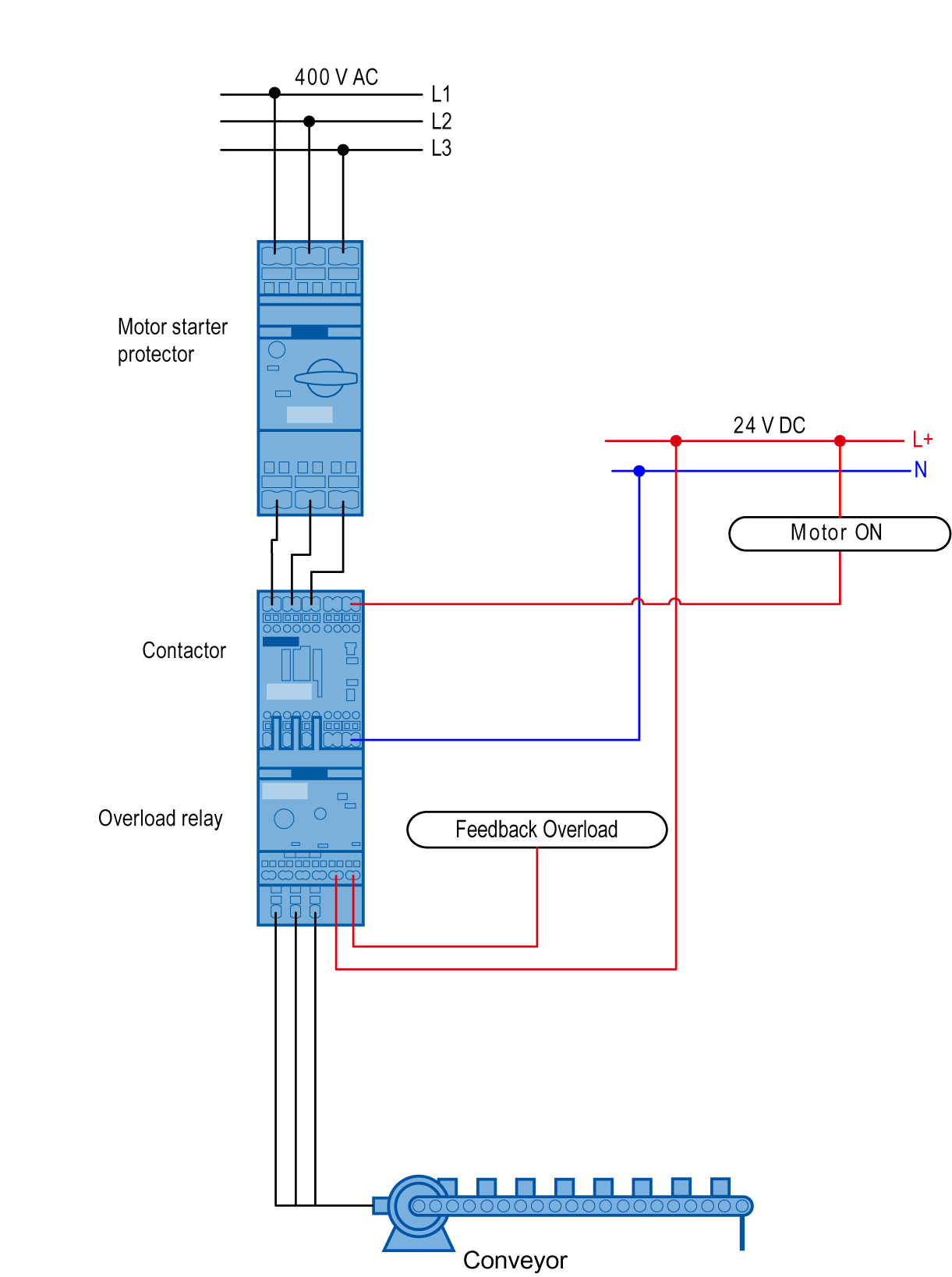
SIRIUS Innovations Load Feeder as a Direct Starter with ...
Siemens – Starters – Deekay Electricals

Siemens 14CP32AA81 Heavy Duty Motor Starter, Ambient ...

Contactors and Motor starters - PLC Tutorial Point
Comments
Post a Comment