40 rankine cycle ph diagram
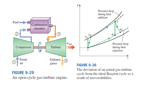
What is Brayton Cycle - pV - Ts Diagram - Definition A large single-cycle gas turbine typically produces for example 300 megawatts of electric power and has 35-40% thermal efficiency. Modern Combined Cycle Gas Turbine (CCGT) plants, in which the thermodynamic cycle of consists of two power plant cycles (e.g. the Brayton cycle and the Rankine cycle), can achieve a thermal efficiency of around 55%. Rankine Cycle Power Plant - an overview | ScienceDirect Topics M.N. Bahadori, in Solar Energy Conversion, 1979 5 The System Operation and Maintenance. The operation and maintenance of the solar Rankine-cycle power plant, or any solar device, are the most important and often neglected factors in developing countries.
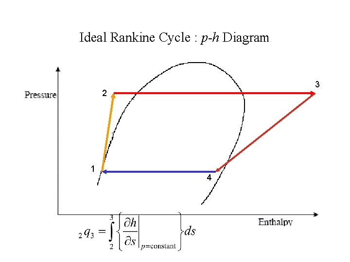
Rankine cycle - Energy Education The pressure volume diagram of the Rankine cycle. This illustrates the changes in pressure and volume the working fluid (water) undergoes to produce work. The steps in the Rankine Cycle as shown in Figure 1 and the corresponding steps in the pressure volume diagram (figure 2) are outlined below:

Rankine cycle ph diagram
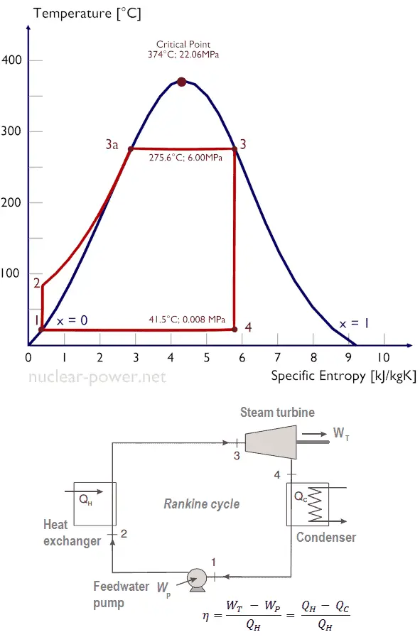
Rankine cycle - Wikipedia There are four processes in the Rankine cycle. The states are identified by numbers (in brown) in the T-s diagram . Process 1-2: The working fluid is pumped from low to high pressure. As the fluid is a liquid at this stage, the pump requires little input energy. Process 1-2 is isentropic compression. Refrigerant Ph Diagram - Heat Exchangers - Brewiki Refrigerant Ph Diagram. For a Carnot cycle (where A Q = TA s), the COP for the refrigeration application becomes (note than T is absolute temperature [K]): Thigh_ Tio and for heat pump application: The COP in real refrigeration cycles is always less than for the ideal (Carnot) cycle and there is constant effort to achieve this ideal value. Rankine Cycle - an overview | ScienceDirect Topics The Rankine cycle is shown in Figure 7.1 [ 1 ]. The working fluid is compressed from low to high pressure (Step 1-2). At this stage, the pump requires little input energy because the fluid is a liquid.
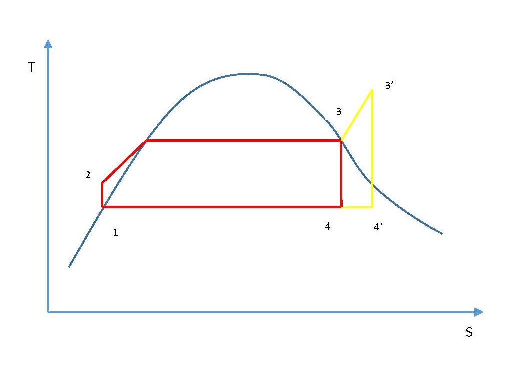
Rankine cycle ph diagram. Thermodynamics eBook: Ideal Regenerative Rankine Cycle T-s Diagram of Lowering the Condenser Pressure : In a simple Rankine cycle, heat is added to the cycle during process 2-2'-3 (see the T-s diagram on the left). During this first stage (process 2-2'), the temperature of the water is low. That reduces the average temperature during heat addition (process 2-2'-3). Ranking of Working Fluids for Organic Rankine Cycle ... recuperated organic Rankine cycle is shown in Figure 1 and consists of four major components: turbine, condenser, pump and evaporator. Figure 1. Schematic of non-recuperated ORC system The following processes take place in the simple (non-recuperated) ORC system. High-pressure vapor enters a turbine (state point 1). XLS nimech.weebly.com Show the cycle on a T-s diagram with respect to saturation lines, and determine (a) the minimum turbine inlet temperature, (b) the rate of heat input in the boiler, and (c) the thermal efficiency of the cycle. Ideal Rankine Cycle MPa Analysis: Wnet(dot) = mdot * wnet Properties determination: Fluid = water, use Table A-4 to A-6 wnet = wt - wp PDF P-h Chart for R134a (SI Units) - Syracuse University Reversed Carnot Cycle s T T C T H. 4 0.0 5.0 10.0 15.0 ... 20.0 30.0 40.0 50.0 60.0 70.0 Carnot Cycle Performance Sat Cond T, °C Reversed Carnot Vapor Compression Cycle s T T C T H. 5 Reversed Rankine Vapor Compression Cycle s T T C T H Superheat Horn Increased Work Ideal Practical Vapor Compression Cycle ... Comparison of P-V Diagrams ...
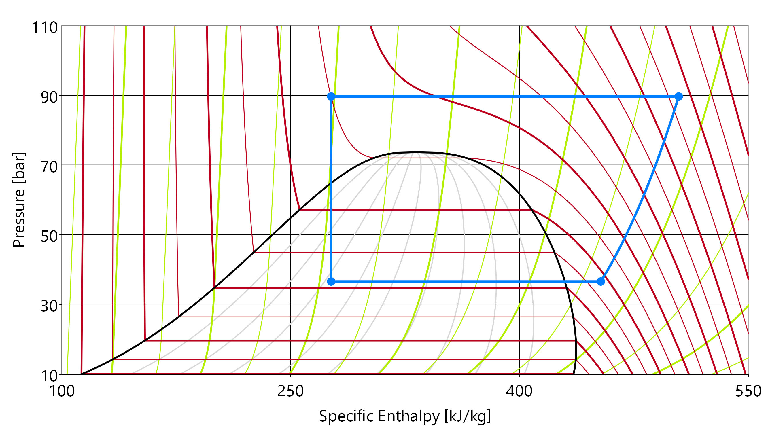
Rankine Cycle - Processes, Efficiency [P-v and T-s Diagram] The following are the four stages of an ideal Rankine cycle: Isothermal expansion Adiabatic expansion Isothermal compression Warming operation 1. Isothermal Expansion The water is isothermally converted into dry saturated steam at a constant temperature (T1) and pressure (P1). The dry state of steam is expressed in point 2. Rankine Cycle - Wolfram Demonstrations Project The irreversible turbine pathway () is the dashed black line on the diagram; the reversible turbine pathway is the orange dashed line. Select "Rankine cycle" to view a schematic of the cycle, and select "turbine" to show the inlet and outlet conditions for the turbine and the work generated. Contributed by: Rachael L. Baumann (November 2014) Chapter 8a: Ideal Rankine and Reheat Steam Power Cycles ... A typical P-h diagram for steam is shown below. One aspect of the diagram that we have ignored until now are the various constant entropy lines drawn in the superheated and high quality section of the diagram. We will use these lines to indicate the path of an isentropic turbine for the ideal cycles described below. Pressure-Enthalpy Diagram For Rankine Cycle - YouTube Describes a Rankine power cycle with steam using a log pressure versus enthalpy diagram. A simulation that contains this log P vs H diagram is found here: ht...
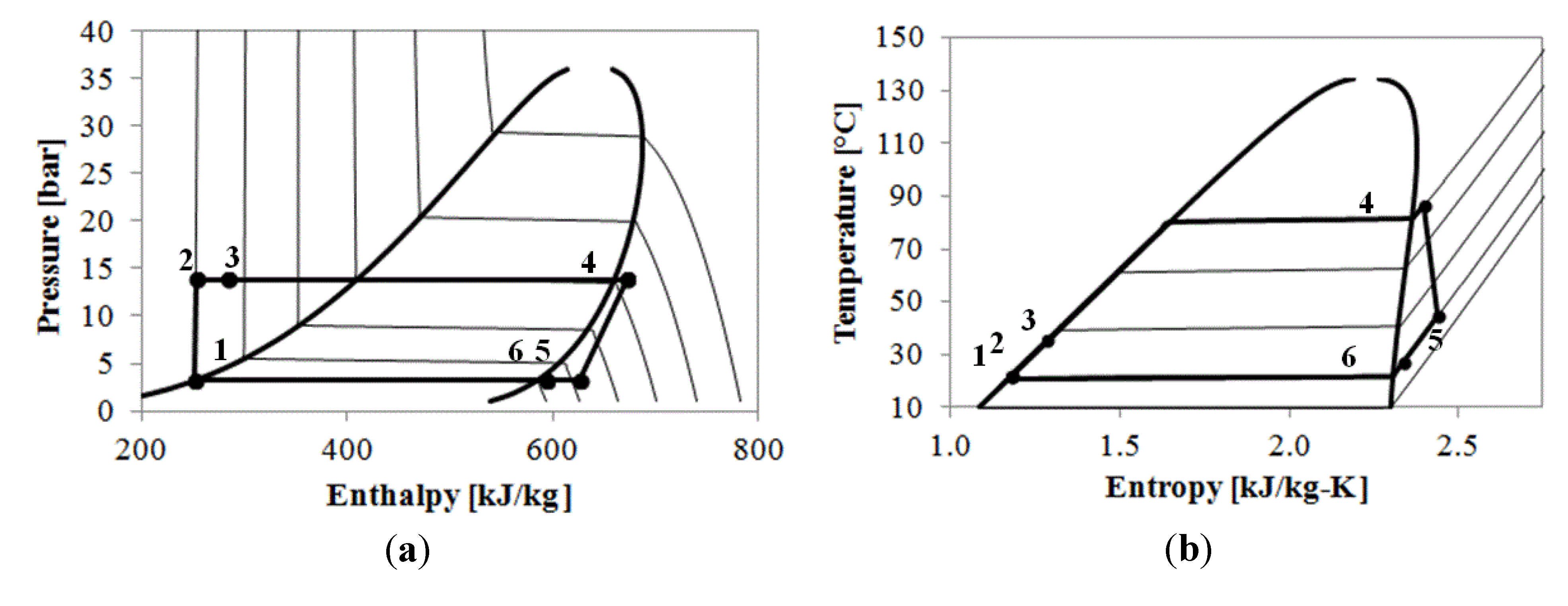
What is Refrigeration Cycle? Basic, Diagram & Explanation ... The refrigeration cycle is the main basic cycle for all air conditioning and refrigeration equipment. In this chapter, we will discuss, basics of a refrigeration cycle, mainly vapor compression cycle, main concept, parts, components, working principle along with a real example, etc. P-V diagram of rankine cycle | Download Scientific Diagram Operation units Complete oxidation approach Partial oxidation approach Energy efficiency of 30% and 20% was taken as the nominal efficiency for a new regenerative steam Rankine cycle with a heat... Log ph diagram online I TLK Energy In the log ph diagram, not only heat pump and refrigeration processes can be represented, but any desired thermodynamic cycle process. Just select an evaporation pressure that is higher than the condensation pressure and you will get an Organic Rankine Cycle (ORC). Rankine Cycle Figure 1 shows the idealized Rankine cycle. The pressure-enthalpy (p-h) and temperature-entropy (T-s) diagrams of this cycle are given in Figure 2. The Rankine cycle operates in the following steps: 1-2-3 Isobaric Heat Transfer. High pressure liquid enters the boiler from the feed pump (1) and is heated to the saturation temperature (2).

Thermodynamics eBook: Ideal Rankine Cycle
P-h Diagram for ORC cycle. | Download Scientific Diagram In this study, we applied a design of an organic Rankine cycle system in the form of a heat exchanger device installed in an ORC system that functions to change the form... Contexts in source...
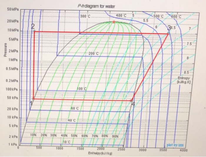
Solved P-hdiagram for water 500 600 C 5.5 20 MPa 0MPa... 7.5 ...
Superheat and Reheat - Rankine Cycle | nuclear-power.com Rankine cycles reheat and superheat the low-pressure stage. In the superheater, further heating at fixed pressure results in increases in both temperature and specific volume. The process of superheating water vapor in the T-s diagram is provided in the figure between state E and the saturation vapor curve.
Explanation of Rankine Cycle | ME 200
Rankine Cycle - Ts, Pv Diagrams, Reheat, Equations ... Rankine cycle P-v diagram The irreversibility's due to the fluid friction, heat loss to the surroundings the Rankine cycle differs from the ideal one. Losses like fluid friction drop the pressure in the boiler, condenser, and the piping between the components, and hence the network output is reduced.
Rankine cycle - Energy Education
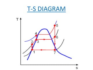
What does the area of Rankine cycle TS diagram mean? Actual Rankine Cycle. 1-2-b-3-4-1. Critical Point (CP) is in centre of the curve as shown in Fig 1-a and 1-b above. The curved lines on the left side of the CP are saturated- liquid lines and the region/area to the left of these lines are called as sub-cooled liquid regions. Consequently, what are the four process of Rankine Cycle?
Internship Report
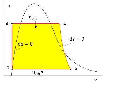
Rankine Cycle - pV, Ts diagram - Nuclear Power When plotted on a pressure volume diagram, the isobaric processes follow the isobaric lines for the gas (the horizontal lines), adiabatic processes move between these horizontal lines and the area bounded by the complete cycle path represents the total work that can be done during one cycle.
Turbine Design for Low Heat Organic Rankine Cycle Power ...
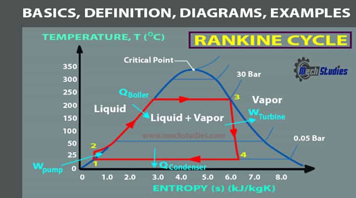
Thermodynamics eBook: Ideal Rankine Cycle The Rankine cycle is an ideal cycle if water passes through the four components without irreversibilities and pressure drops. The ideal Rankine cycle consists of the following four processes, as shown on the T-s diagram on the left: 1-2: Isentropic compression in a pump.
USE THE PROVIDED P-h diagram to solve. Your answer | Chegg.com
Answered: In a Rankine Cycle , saturated liquid… | bartleby Question. In a Rankine Cycle , saturated liquid water at 1 bar is compressed isentropically to 150 bar. First by heating in a boiler and then by superheating at constant pressure of 150 Bar, the water substance is brought to 750 K. After Adiabatic reversible expansion in a turbine at 1 Bar, it is then cooled in a condenser to a saturated liquid.

Analysis of Constant Pressure Steam Generation - ppt download
Ideal Rankine Cycle - IIT Kanpur The practical Rankine cycle is shown as 1-2'-3-4'-1. In the actual turbine, the work delivered is less than the isentropic turbine. Similarly, the work consumed by an actual pump is greater than the work consumed by an isentropic pump. That is, h3-h4' < h3-h4 h2'-h1> h2-h1 Thermal efficiency of a practical Rankine cycle,
Power Plant Efficiency – Simulator Laboratory
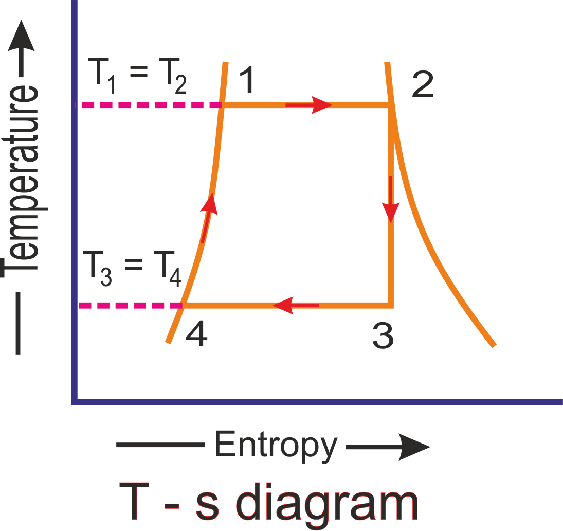
Carnot Cycle Ph Diagram - vendors.metro.net Carnot Cycle Ph Diagram Rankine cycle - Wikipedia In an ideal Rankine cycle the pump and turbine would be isentropic, i.e., the pump and turbine would generate no entropy and hence maximize the net work output. Processes 1-2 and 3-4 would be represented by vertical lines on the T-s diagram and more closely resemble that of the Carnot ...
Thermodynamic analysis of R134a in an Organic Rankine Cycle ...
What is Rankine Cycle - pV, Ts diagram - Definition The Rankine cycle is often plotted on a pressure volume diagram ( pV diagram) and on a temperature-entropy diagram ( Ts diagram ).
Was ist Clausius-Rankine-Kreisprozess - Dampfturbine Cycle ...
Rankine Cycle - SlideShare • The Rankine cycle is a cycle that converts heat into work. The heat is supplied externally to a closed loop, which usually uses water. This cycle generates about 90% of all electric power used throughout the world.
Rankine Cycle - Ideal Rankine Cycle efficiency ...
Rankine Cycle - an overview | ScienceDirect Topics The Rankine cycle is shown in Figure 7.1 [ 1 ]. The working fluid is compressed from low to high pressure (Step 1-2). At this stage, the pump requires little input energy because the fluid is a liquid.

ACTUAL RANKINE CYCLE VERSUS IDEAL RANKINE CYCLE ...
Refrigerant Ph Diagram - Heat Exchangers - Brewiki Refrigerant Ph Diagram. For a Carnot cycle (where A Q = TA s), the COP for the refrigeration application becomes (note than T is absolute temperature [K]): Thigh_ Tio and for heat pump application: The COP in real refrigeration cycles is always less than for the ideal (Carnot) cycle and there is constant effort to achieve this ideal value.

The Rankine cycle | The steam turbine
Rankine cycle - Wikipedia There are four processes in the Rankine cycle. The states are identified by numbers (in brown) in the T-s diagram . Process 1-2: The working fluid is pumped from low to high pressure. As the fluid is a liquid at this stage, the pump requires little input energy. Process 1-2 is isentropic compression.

2.3 The basic cycle in a log Ph diagram - SWEP
TIL Suite
International Journal of Energy Applications and Technologies ...

Thermodynamic 1: Rankine Cycle
An introduction to thermodynamics applied to Organic Rankine ...
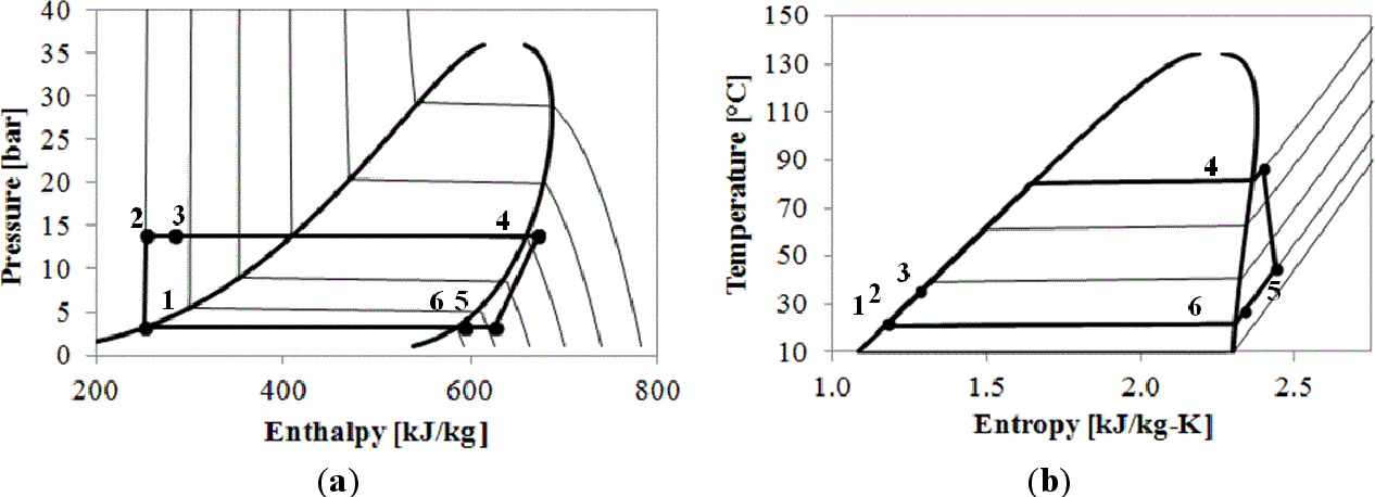
Figure 2 from Thermal-Economic Modularization of Small ...

Refrigeration cycle diagram explained - Refrigeration - HVAC ...
![Rankine Cycle - Processes, Efficiency [P-v and T-s Diagram]](https://www.theengineerspost.com/wp-content/uploads/2019/09/p-v-diagram-of-rankine-cycle.png?ezimgfmt=rs:348x306/rscb19/ng:webp/ngcb19)
Rankine Cycle - Processes, Efficiency [P-v and T-s Diagram]
Preliminary analysis of organic Rankine cycles to improve ...
Rankine Cycle
Bachelor Thesis 1_ORC_Schwarzbauer_r00

T-S and P-H Diagrams
General Concepts for Development of Thermal Instruments P

Clausius-Rankine-Kreisprozess – Wikipedia

Rankine Cycle: What is it? (Ideal vs. Actual + Diagram ...
Rankine Cycle - Ts, Pv Diagrams, Reheat, Equations, Examples ...

Pressure/enthalpy chart of Rankine cycle with R134a for first ...

Refrigerant Ph Diagram - Heat Exchangers - Brewiki
Supercritical Carbon Dioxide Fluid and Its Application to ...

Chapter 8a: Ideal Rankine and Reheat Steam Power Cycles ...
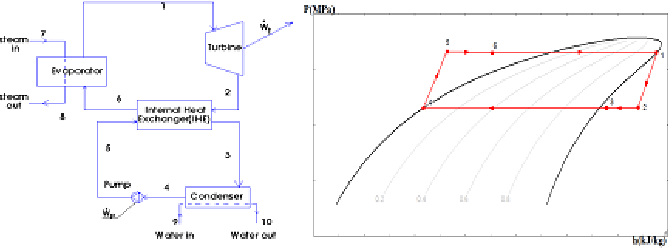
Figure 3 from Comparison of Different Working Fluids ...
Energies | Free Full-Text | Thermal-Economic Modularization ...

Rankine cycle - EEE Made Easy

Rankine Cycle Examples
A comparing on the use of Centrifugal Turbine and Tesla ...

Rankine Cycle | twinkletwinklelittlestar
Comments
Post a Comment