40 3 to 1 pulley system diagram
PDF pulley3 3. The diagram below shows two pulley wheels connected with a belt. In order for the pulley system to work, the belt is 'pulled' tight between the pulley wheels. What would happen if the belt was 'slack' (not tight)? en.wikipedia.org › wiki › Block_and_tackleBlock and tackle - Wikipedia Diagram 3 shows three rope parts supporting the load W, which means the tension in the rope is W/3. Thus, the mechanical advantage is three-to-one. By adding a pulley to the fixed block of a gun tackle the direction of the pulling force is reversed though the mechanical advantage remains the same, Diagram 3a. This is an example of the Luff tackle.
Block and Tackle Pulley System | Options and... | Dlubal Software The following text describes four pulley system options with downward tension force. In the model file, which you can download at the end of this article, you find a structure that is as realistic as possible, including a simple schematic modeling for better understanding the behavior. This example shows for...

3 to 1 pulley system diagram
How to Calculate First, Second and Third Pulley Systems First System of Pulleys. As can be seen from the diagram, the lowermost pulley here carries the load (being lifted), which is fixed and hangs over the axle of the pulley. An end of the string T1 attached firmly to an upper rigid frame, passes across the groove of this pulley and attaches its other to the... Diagram showing a pulley system with a 6:1 mechanical advantage Pulley Systems - Flaschenzug. This document shows you how to make an effective and useful pulley system. If you study the pictures, you will be able to understand how the ratio of a pulley system is calculated. Understand that the maximum load to the break in a pulley system should not be... 3:1 Pulley System - YouTube This video demonstrates how to set up a simple 3:1 pulley with a Petzl Reverso. Note that the Reverso acts as a 'progress capturing device' as it allows...
3 to 1 pulley system diagram. The 3 kinds of pulley systems — Alpine Savvy In a simple pulley system, when the rope end terminates and is attached at the anchor, then the MA This can allow you to completely collapse the 3 to 1 system before the 2 to 1 system collapses Compare this with the compound 6:1 diagram just above. With the 6:1, you get a little more MA, plus... Pulley Problems and Constraint Equation | Physics Pulley ... Now, from the Free Body Diagram (FBD): ... This is an example of a Fixed Pulley System. CASE – 2. Consider the following pulley system: First, we have to relate the tension between string 1 & string 2, Consider FBD of pulley B: 2T 1 – T 2 = M B.a B. 2T 1 = T 2. . . . . . . . . (4) (Since the pulley is massless) Now, Consider the accelerations as shown in the below figure: For String 2 ... Pulley - 3D CAD Models & 2D Drawings | Free body diagrams The drive element of a pulley system can be a rope, cable, belt, or chain that runs over the pulley inside the groove or grooves. Diagram 3a: The Luff tackle adds a fixed pulley "rove to disadvantage." The tension in the rope remains W/3 yielding an advantage of three. VECTOR ADDITION CALCULATOR (see diagram below) MAGNITUDES can be in any units but you must BE CONSISTENT. For example, if you are inputting pounds then ALL magnitudes have to be in pounds. The same would apply to newtons, dynes, etc. So you may use any magnitude units you like but DO NOT MIX UNITS. As a practice example try entering these 4 vectors: 1) 4 newtons 127 degrees. 2) 3 …
PDF Enhanced Ackermann Both the cam-pulley system and the independent swerve drive system proved to be viable options based upon the prototypes. To determine which design to utilize, a cost matrix was created that compared different aspects of each system (Table 3). Each metric was rated on a scale of one to five... A pulley system — Collection of Solved Problems Ignore the masses of the pulley system and the rope. The bucket moves up and the block moves down. Because we leave the mass of the pulley system and the rope out of account they have no moment of inertia and don't affect the tension forces. Question about a simple free body diagram | Physics Forums 15.01.2022 · In this diagram, if the system begins by being held static, and then at time ##T## release of all components occurs, at all times ##>T##, until vertical movement stops upon vertical block ##m## making contact with the Normal Force at the base of block ##M##, will the lateral acceleration of vertical block ##m## be steadily equal to the lateral acceleration of block … byjus.com › icse-class-10-physics-selina-solutionsSelina Solutions Concise Physics Class 10 Chapter 3 ... - BYJUS A pulley system has a velocity ratio 3. Draw a diagram showing the point of application and direction of load (L), effort (E) and tension (T). If lifts a load of 150 N by an effort of 60 N. Calculate its mechanical advantage. Is the pulley system ideal? Give reason. Solutions: Load = 150 N. Effort = 60 N. Mechanical advantage = Load / Effort ...
System of Pulleys — Mechanical Advantage Calculator • Mechanics... A simple pulley system, where the end of the line is attached to the anchor, has the mechanical advantage, which is Two simple pulley systems are shown in the pictures above. Moving pulleys provide mechanical advantage, which is the factor, on which the input force (or effort) is multiplied. Why is the mechanical advantage of the first pulley pictured... - Quora The first FBD solves for the reaction forces on lef... The first FBD solves for the reaction forces on left pulley under the assumption of static equilibrium…if we move really fast we need an MAD (mass-acceleration diagram) and have to do a lot more work. PDF Dynamic Simulation for Multi-Body If system has more objects such as in a multi-body system, friction model should be modied accordingly, which was presented by Klepp [15]. Pulley and belt mechanisms can be found mainly in transmission devices transfering power from one Figure 2-3: Free Body Diagram of a Revolute Joint. Full guide to creating a HTD timing pulley in CAD (Fusion 360) • First a few notes about the HTD tooth profile. The correct profile courtesy of SDP-SI is shown below. Grateful for the guide - but where did you get the tooth width of 3.05mm for this 5mm tooth belt? I'm adapting it to 3mm teeth and can't find an equivalent dimension in the specs/.
TOMCHY 3 in 1 Pulley System Gym with Standby Pulley Plus, LAT ...
pulley systems diagrams - Search How to diagram a pulley system! Anchor point The anchor point should be a solid black box fixed to a surface. Dot Draw a large dot to show where the The above diagrams depict theoretical frictionless systems, in the real world, pulleys do add friction. Rescue pulley manufacturers publish friction...

3:1 Mechanical Advantage
Pulley Calculator | Pulley system A pulley system consists of two pulleys (usually of different diameters) and a belt loop to link the pulleys. In the figure above, the belt is marked with There are two main parameters associated with each of the pulleys. The first one is the diameter (twice the radius), and the second one is its angular...

Pulleys
3 To 1 Pulley System Diagram - Wiring Diagram Source Mechanical advantage explained educated climber this setup differs from the zrig setup in that the actual rope attached to the load does no...
Mechanical Advantage Systems 1
› one-half-hp-garage-door-opener8165W | Contractor Series - 1/2 HP Garage Door Opener ... Support standard aluminum doors day after day with the 1/2 HP AC motor. 75% Less Power. Consume up to 75% less power in standby mode. Durable Chain Drive. Count on long-term reliability with the durable chain drive system.

Block and Tackle Pulley System | Options and Modeling ...
kids.kiddle.co › PulleyPulley Facts for Kids - Kiddle Jul 16, 2021 · A fixed pulley is used to redirect the force in a rope (called a belt when it goes in a full circle). A fixed pulley has a mechanical advantage of 1. The static pulley has a wheel and an axle. Movable A movable or class 2 pulley has an axle that is "free" to move in space. A movable pulley is used to transform forces.
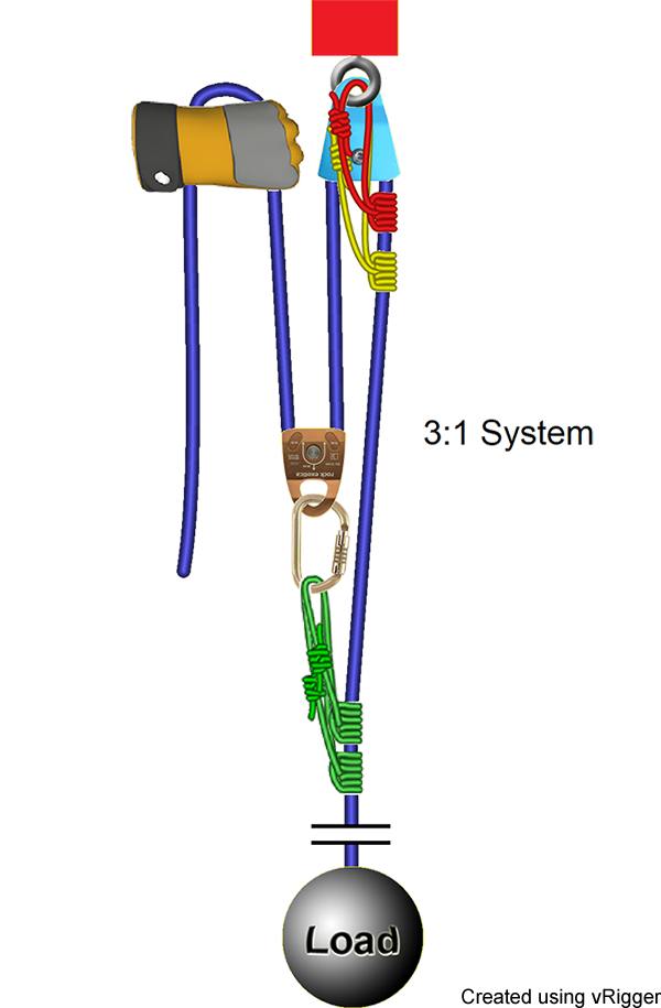
Rope Rescue 3:1 System
Pulley systems - Mechanical devices - Eduqas - GCSE Design and... Single pulley systems are demonstrated in cranes, lifting a bucket from a well, raising a flag or adjusting window blinds. One pulley doesn't make a mechanical advantage, as the same amount of force is needed. However, if additional pulleys are added, a mechanical advantage is created.
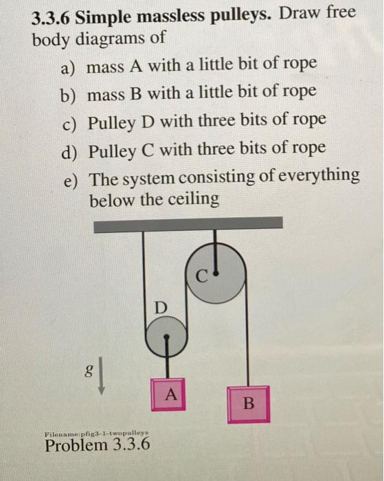
Solved 3.3.6 Simple massless pulleys. Draw free body | Chegg.com
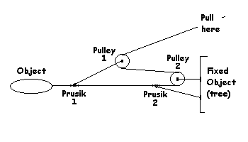
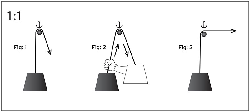
How to build a 3:1 mechanical advantage system First rig a 1:1 system. The rope comes from the load and goes through one pulley. Easy enough. Now add "capture" Prusiks that will hold the load if you let go This approach of first rigging a 1:1 system and then, if required, adding a traveling Prusik and pulley simplifies the rigging of a 3:1 system.

Engineering and Architecture sur Instagram : Pulley systems ...
Pulley System - Definition and Mechanism A pulley system is an easy way to lift heavy objects, as compared to lifting the object barehanded. A single pulley only serves to change the direction of the applied force. The circumference of the pulley system is surrounded by flanges that contain grooves or grooves to locate the table and the belt.

Overview of a simple pulley system — Alpine Savvy
The 3:1 Pulley System - ropebook First one end of the rope is attached directly to the load, this is then passed around an anchored pulley (pulley B) and returns back to the load where An easy way to calculate the ratio of a pulley system is to count the amount of lines that apply effort on the load. In this system there are three ropes that...
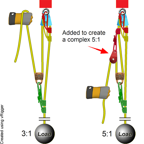
Rope Rescue 5:1 System
learnmech.com › epicyclic-gear-train-workingEpicyclic Gear Train- Diagram, Parts, Working, Advantages ... A good example of the everyday application of a planetary gear system is the automatic transmission of a car. The epicyclic gear trains are used in the back gear of lathe, differential gears of the automobiles, hoists, pulley blocks, wrist watches, etc.
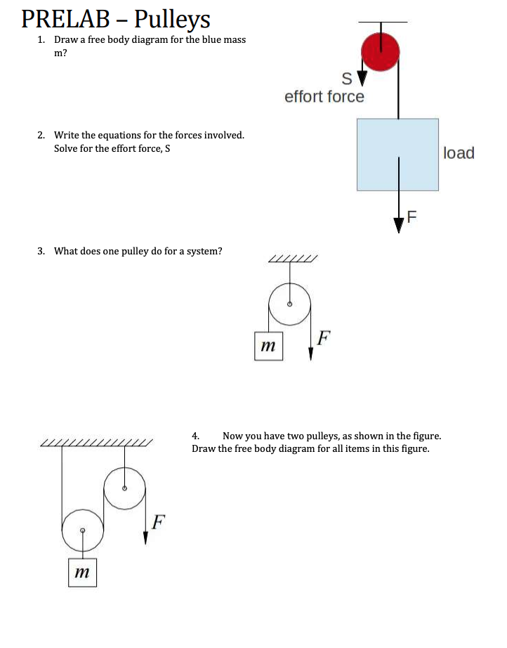
Solved PRELAB – Pulleys 1. Draw a free body diagram for the ...
Pulley System | PDF | Belt (Mechanical) | Mechanics Diagram 2a: Another simple pulley system similar to diagram 2, but in which the lifting force is redirected downward. A practical compound pulley corresponding to diagram 2a. The simplest theory of operation for a pulley system assumes that the pulleys and lines are weightless, and that...

How to use the Slacktivity HangOver-Pulley System (including force measurements)
The Physics of Pulley Systems | Sciencing Pulley systems are used in mechanics problems in physics. The best way to solve pulley problems in mechanics is by utilizing Newton's second law of motion and understanding Newton's third and first laws of To begin, draw a free body diagram of all the forces acting on the system, including tension.
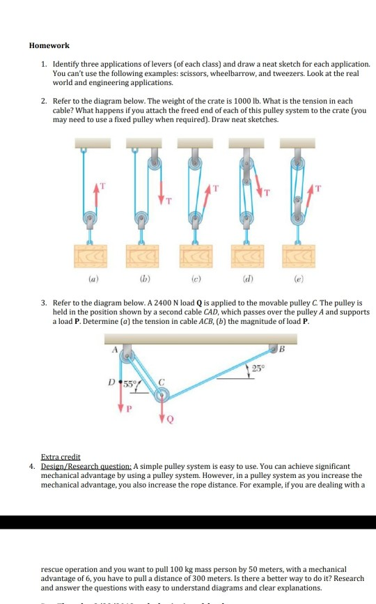
Solved Homework 1. Identify three applications of levers (of ...
PDF Module 3: Architecture of Hybrid and Electric Series Hybrid System: In case of series hybrid system (Figure 4a) the mechanical output is first converted into electricity using a generator. Therefore, these hybrid systems are classified into two categories: the ICE dominated and the EM dominated. r 1 Pulley or Chain Assembly r3.
schoolphysics ::Welcome::
Simple Machines: Pulley Systems and Their Working... - Science Struck The pulley system works on the basis of transfer of reduction of the load weight, which is experienced by the person applying the effort. The load is tied at one end of the rope or cable that has resistance, while the other end is characterized by the presence of effort. Modern pulley systems are more or...

3 Types of Pulleys | Pulley, Simple machines, Block and tackle
Rescue Pulley System Diagram Rope Rescue Pulley Systems Diagrams. ... Rope Pulley Diagram Wiring Data. ... Pulleys and mechanical advantage systems cmc pro crevasse This is a image galleries about 5 To 1 Pulley System Rescue.You can also find other images like wiring diagram, parts diagram, replacement...

Mechanical Advantage for Pulley Systems | Mechanical ...
Basic Pulley Mechanisms : 17 Steps (with Pictures) - Instructables A belt and pulley system is one of the simplest types of pulley systems. As I described before, it contains two pulleys, one driving the belt and one driven by a belt. Can anyone send a diagram to help me determine the cord positioning to make this happen?

DNA pulley system. ( A ) Schematic of the experiment. The ...
Hand Pulleys - Physiopedia Original Editors Curtil Louis. Top Contributors - Curtil Louis, Vidya Acharya, Kim Jackson, Lucinda hampton, Admin, Candace Goh, WikiSysop and Aminat Abolade. The pulley system is made of thickened areas of the flexor tendon sheath and plays an important role in: flexion...
A Primer on Pulley Systems 1
Pulley - Wikipedia Diagram 3 shows that now three rope parts support the load W which means the tension in the rope is W/3. Thus, the mechanical advantage is three. By adding a pulley to the fixed block of a gun tackle the direction of the pulling force is reversed though the mechanical advantage remains the same, Diagram 3a. This is an example of the Luff tackle.

Pulley system composition – a systematic approach
12.1 Pulley Problems - Part I, Set up the Equations | Week 4: Drag... And I want to first consider separately pulley B and block 2. Now in some ways when you're looking at a compound system, and it has four objects, it makes So I've now drawn the free body diagram of the various objects. And that enables me to apply Newton's second law for each of these objects.
Pulley system efficiency tests with MAESTRO, I'D S, PRO ...
Easy DIY Pulley System | 3 Homemade Cable Machines... You can make a DIY Pulley System for your home gym in 15 minutes. This homemade cable machine is great for triceps pulldowns and working out your lats. When you think about cable pulleys, the first two workouts that come to mind are triceps and back. However, there are so many more exercises...
The 3:1 Pulley System - ropebook
› 1998-2005-benz-ml320-ml3501998-2005 Benz ML320 ML350 ML500 Fuse Box Location Diagram ... Fuse # Pupose, Designation, Function: Ampere: 1: 12 volt outlet socket: 15: 2: Left turn signal lamps: 7.5: 3: Right main headlight, head lamp: 7.5: 4: Sunroof, moon ...
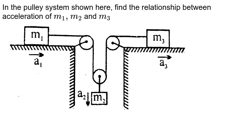
A system of masses and pulleys is arranged in a vertical plane as
3:1 Pulley System - YouTube This video demonstrates how to set up a simple 3:1 pulley with a Petzl Reverso. Note that the Reverso acts as a 'progress capturing device' as it allows...
A Primer on Pulley Systems 1
Diagram showing a pulley system with a 6:1 mechanical advantage Pulley Systems - Flaschenzug. This document shows you how to make an effective and useful pulley system. If you study the pictures, you will be able to understand how the ratio of a pulley system is calculated. Understand that the maximum load to the break in a pulley system should not be...

3-1 pulley systen setup or Z-rig (SMARTER NOT HARDER)
How to Calculate First, Second and Third Pulley Systems First System of Pulleys. As can be seen from the diagram, the lowermost pulley here carries the load (being lifted), which is fixed and hangs over the axle of the pulley. An end of the string T1 attached firmly to an upper rigid frame, passes across the groove of this pulley and attaches its other to the...
How Efficient are Pulleys and Related Devices used by BWRS in V

the moment of inertia of the pulley system as shown in the ...

http://www.zpag.net/ | Pulley, Mechanical engineering design ...

Blog Archives

Pulley System Question : r/AskPhysics
Crevasse Rescue Skills | REI Co-op
DMM Professional - Resistance is futile

A Single Movable Pulley and Mechanical Advantage | Science ...

A pulley with a radius of 3.0cm and a rotational inertia of ...
File:Z drag.png - Wikimedia Commons

Using carabiners as pulleys

How to Calculate First, Second and Third Pulley Systems ...
DMM Professional - Resistance is futile
Solved PRE-LAB 4: Simple Machines 1. (3 pts) Draw a | Chegg.com
Pulley system analysis | RopeLab Online

Calculating the Ratio of a Pulley System | Gravity Training
Comments
Post a Comment