43 tarp switch wiring diagram
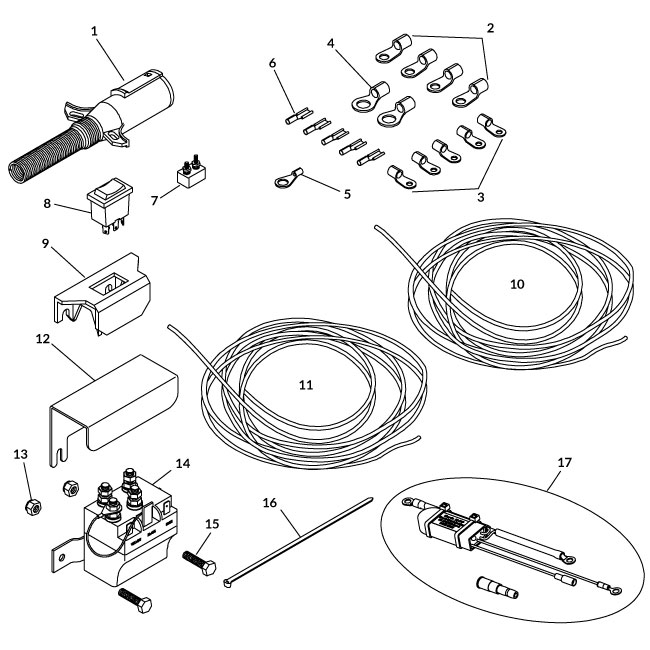
Roll Tarp Systems SOLENOID REPLACEMENT INSTRUCTIONS Disconnect solenoid wires beginning with number 1 as shown at right. Remove and discard old solenoid. Mount new solenoid using #2 self drilling screws. Cut off existing terminals on wires and replace with new terminals as in diagram at right. Reattach wires to solenoid as in diagram at right. ... River Rv Wiring Diagrams R Pod Wiring Diagram Wiring Diagram ... Forest River Rv Wiring Diagrams Wiring Diagram Rv Park Wiring Diagram Operations
Terminal Ignition Switch Wiring Diagram and Rotary Tarp Switch Wiring Diagram ... Marine Battery Switch Wiring Diagram and Boat Switch Wiring Diagram

Tarp switch wiring diagram
This diagram does contradict the Lenz rule of thumb for the use of the BM1 ('Right is Right' implying that the BM1 should only be in the right rail) but does make the wiring easier and minimizes the number of insulated rail joints required. Wiring Diagram for Ceiling Light with Switch Fresh Need Wiring. ... This diagram illustrates wiring for one switch to control 2 or more lights. 16.12.2013 · Also, your frozen throttle switch could be shutting it down. These are a few things to check. If you need more help, our tech department can walk you through more options. Their number is 320-358-3409. Good luck! Reply. austin corcuera says: September 25, 2014 at 5:50 pm. some people told me it could be my fuel pump or my filter and a gas line could be kinked. …
Tarp switch wiring diagram. Bulletproof Tarp Motor (60:1) Part #13732 Powerhouse Heavy Duty Motor Part #11248 ROCKER EZ Switch Kit Part #12250 Trombetta Direct Replacement Relay Part #12244 Rotary Switch Part #11129 4 Spring Galvanized Steel Arm Kit Part #12223 4 Spring Polished Aluminum Arm Kit Part #11564 40 & 50 Amp Circuit Breakers Part #11156/13720 We always make sure that writers follow all your instructions precisely. You can choose your academic level: high school, college/university, master's or pHD, and we will assign you a writer who can satisfactorily meet your professor's expectations. Tarp Switch Wiring Diagram, Donovan Tarp Switch, Electric Tarp Switch, HHH Rotary Switch Wiring Coil Split, 2-Way Switch Wiring Diagram. Tarp Motor Wire Asm (not shown) ROLTEC® ELECTRIC TARP CONVERSION PARTS DIAGRAM. 31 Solenoid, Motor Reversing 12V w/ Jump Wire. Solenoid/Relay kit. 5. Enough wire to do complete installation of motor kit. Wiring Diagram Free Wiring Diagram On Wiring Diagram Schematic ... Headlight Switch Wiring In Addition Brake Light Switch Wiring Diagram
Basic tips for routing the electrical power conductors for a tarp motor and cab-mounted switch assembly on a dump truck. If you have questions, please give ... Assortment of electric tarp switch wiring diagram. A wiring diagram is a streamlined conventional photographic depiction of an electrical circuit. It shows the elements of the circuit as streamlined forms, as well as the power and also signal links between the gadgets. Tarp Switch Wiring Diagram, Donovan Tarp Switch, Electric Tarp Switch, HHH Rotary Switch Wiring Coil Split, 2-Way Switch Wiring Diagram. 4Z 15/ I replace this electric motor and it has 4 lugs - I have 3 wires blk, red and white. There is a sticker on wiring diagram (ideally color) for Dayton belt drive motor Model 3KJ . A first consider a ... Buyers Saltdogg Spreader Parts, Find Parts Easy with our Part Diagrams. SaltDogg® Spreaders from 100 lb. up to 16 yd. capacity. From Walk-Behind Spreaders, to Electric Drive, Gas Powered or Hydraulic Drive Spreaders, we have all the salt spreader parts that you may need to repair your salt spreader.
Roll·Rite is the leading manufacturer of electric tarp systems, tarps, gear motor technology and automated power solutions for the heavy duty trucking industry serving the Construction, Agriculture, Refuse & Recycling Markets. Our tarp systems efficiently and reliably contain and protect payloads, create a safer work environment for drivers, and maximize ROI by increasing … Nov 11, 2021 · Parts Catalog 2022 Ordering/Contact Information 5 New Products 6 Thunder 7000 Power Tarp System 7-13 XR Thunder Power Tarp 6000 Series 9-14 Thunder Power Tarp 5000 Series Parts 14-15 TM One-Touch ... How to assemble a Dump Truck Tarp System Rotary Switch Kit. The rotary switch controls the direction of the tarp system on the dump body or trailer of the tr... schematron.org 1. Electrical Specifications. Minimum THEN CONFIGURE the wires as shown in Diagram 2. 3.HES Series Electric Strike - The original completely surface mounted solution - updated! With a new enhanced design, the series Genesis III™ continues to set the standard for surface mounted electric strikes.
AAATarps.com
Please download these electric tarp switch wiring diagram by using the download button, or right click on selected image, then use Save Image menu. Wiring diagrams help technicians to view the way the controls are wired to the system. Many people can read and understand schematics referred to as label or line diagrams.

220 PVC BIKE-WIRING DIAGRAMS ideas | automotive electrical ...
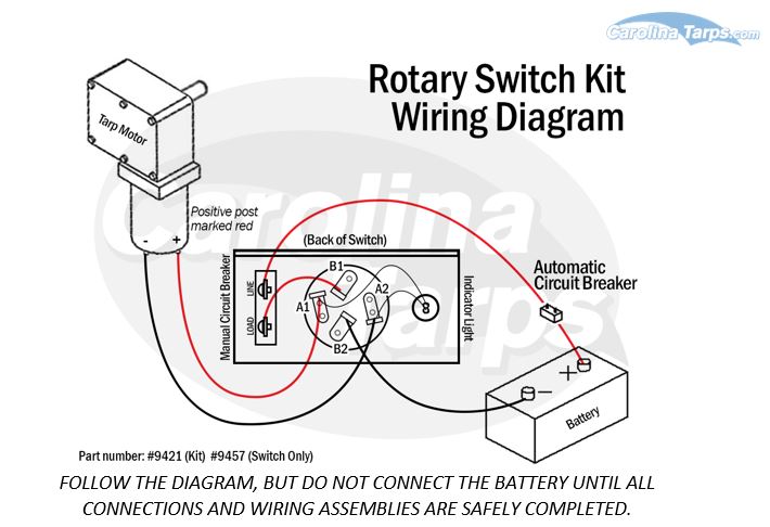
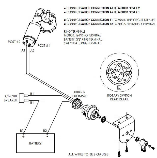
Rotary Switch Kit. Item #: 9421. Price: $39.00. Qty: 5.0 star rating 1 Review. The rotary switch controls the direction of the tarp system on your dump body or trailer of your truck. This is the complete rotary switch kit with switch, circuit breaker, etc. Does not include wiring/motor. 3/8" threaded shaft.

Modeling neurological disease processes using process algebra ...
Nov 04, 2018 · 1 way light switch wiring diagram; 1/4 speaker cable wiring diagram; 10 switch box wiring diagram; 100 amp manual transfer switch wiring diagram; 100 amp service panel wiring diagram; 1000 watts power amplifier schematic diagram; 11 pin relay wiring diagram; 110v plug wiring diagram uk; 12 pin trailer socket wiring diagram; 12v 2 prong toggle ...
Cab Wiring Kit - 50 Amp SMARTâ„¢ Circuit Breaker - Rocker Switch
30.09.2021 · N. Korea's parliamentary session. This photo, released by North Korea's official Korean Central News Agency on Sept. 30, 2021, shows Kim Song-nam, director of the International Department of the ruling Workers' Party's Central Committee, who was elected as a member of the State Affairs Commission, the country's highest decision-making body, during …

2670) - CASE TRACTION KING TRACTOR (1/71-12/79) (04 ...
Tarp Rocker Switch Kit with Solenoid. Buyers Products Tarp Rocker Switch Kit with Solenoid includes a wiring harness, circuit breaker, mounting bracket, and all necessary hardware. It's everything you need to operate a tarp gear motor. 5541020 Tarp Rocker Switch Kit with Solenoid.
80500_J Comand 10 Electric Remote Instructions.indd
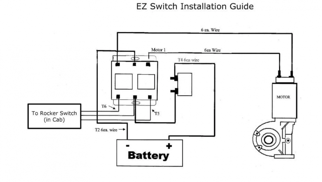
Rocker Switch (Back) (Front) M3 T2 M1 T6 T4 T5 Wiring Directions M1 Motor M3 Motor T2 Battery Ground T4 Middle Terminal Rocker 50 Amp Breaker to Positive Battery T5 Bottom Right Terminal (blue wire) T6 Bottom Left Terminal (red wire) 6 GA 6 GA 6 GA 6 GA ISSUE DATE:09/21/20 . US"6FÈ Covering America OPEN TARP CLOSE . Author ...
2021 GC PID (REX-C100) Mod: Boiler is banding between 115 and ...
electric tarp switch wiring diagram - What's Wiring Diagram? A wiring diagram is a type of schematic which utilizes abstract pictorial icons to show all the interconnections of components in a system.

Rotary Switch Kit Assembly - e-tarps.com
Aluminum.electric tarp motor wiring diagram - A Beginner s Guide to Circuit Diagrams A first check out a circuit representation might be complex, yet if you can review a subway map, you can read schematics. The objective is the same: getting from point A to direct B. Literally, a circuit is the course that permits electricity to circulation.
Rotary Switch Kit
Straightaway Wire Diagram ETL listed outdoor electrical inlet box is prepared for a 50 Amp SS2-50P generator cord. It is designed to be installed outdoors in an open area where the generator is ready for backup power during a power outage. Enough Room for Wiring It's easy to get the wires in the proper spot with the removable front panel. This ...

Installing a Dump Truck Tarp Motor - YouTube
Dimension: 2387 x 3295. DOWNLOAD. Wiring Diagram Pictures Detail: Name: electric tarp motor wiring diagram - 12 Volt 1 1 Horsepower Electric Motor Drive Kit For Single Cable. File Type: JPG. Source: pulltarps.com. Size: 50.85 KB. Dimension: 500 x 375. See also Electric Water Heater Wiring Diagram Gallery.

Aero 0755-962131 Reverse DC Rocker Switch Kit, 12 Volt, 50 Amp.
braun wheelchair lift wiring diagram – Building electrical wiring representations reveal the approximate places and interconnections of ...

Electric Wiring Kit Replacement Parts | Agri-Cover Roll Tarps
Sep 22, 2016 · *This diagram shows the simple wiring diagram for negative ground Delco SI series alternators.* The ignition switch is most commonly powered from the starter battery stud, but source may vary depending on application. With key on power is then transferred through the no charge indicator light to the #1 spade on the alternator regulator connection.
724 Workstation Monitor Installation, Operation and Maintenance
ON/OFF/REMOTE switch on module must be in REMOTE position for wireless con-trols to operate the remote and optional wired wall switch. The wireless control and receiver (housed in the control module) communicate to and from each component via radio frequency. They must remain within 30 feet of each other. For the RC300, when in thermostat mode, transmission of …
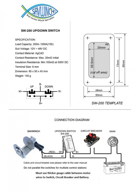
Wiring Diagram - Savwinch Boat Anchor Winch Specialists
Shur-Co provides published Owners Manuals and/or Installation Instructions for all products sold. Have questions feel free to reach out to us directly.

Amazon.com: ALL TRUCK PRODUCTS TARP Motor Rotary Switch KIT w ...
Aviation History magazine is an authoritative, in-depth history of world aviation from its origins to the Space Age. Aviation History offers air enthusiasts the most detailed coverage of the history of manned flight, with action-packed stories and illustrations that put the reader in the cockpit with pilots and military (Army, Navy, and Marines) aviators to experience aviation’s greatest dramas.

EXT Electric Tarp Switch in cab
2. A shorted or loose connection in the wiring configuration or wiring harness 3. Improper wall switch wiring. 4. Module is not grounded 5. Faulty module Solution #1 Verify that the transformer is installed and plugged into the module. Check voltage of transformer under load at the spade connection on the module with the ON/OFF switch in the

MONI-PT100-EXE RTD Sensor Assembly for Hazardous Areas | nVent
Before cutting wire, always preplan wire routing and make necessary adjustments as needed. Tip: Use dielectric grease (packet included) at all electrical connections. A. Route heavy gauge wires from battery to Switch Control and from Switch Control to tarp motor. Allow ample wire where cutting and mounting connections take place.
Installation Operation Maintenance
and the heavy #6 wire included with the kit must be used. Refer to the Roll Rite wiring diagram for reference. The relay has been already mounted on the trailer and the momentary switch that rolls/unrolls the tarp is in the control box installed previously. All that needs to be done is to run a wire from the battery to the female
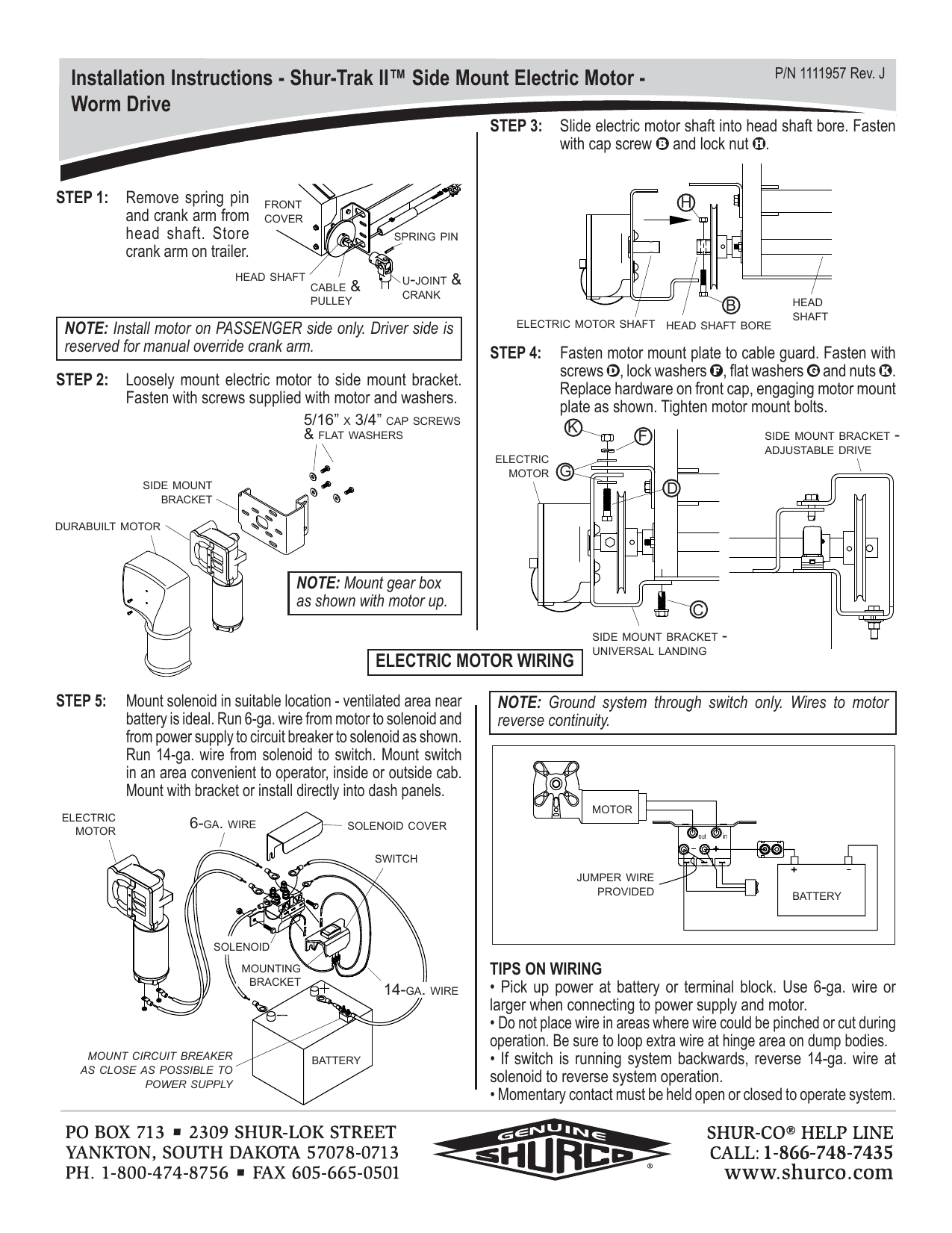
1111957 Electric Motor - Shur-Trak.indd - Shur-Co. | Manualzz
Universal & Electrical Replacement Parts from US Tarp Universal Replacement Parts Electrical and Universal Replacement Parts Wireless Remote Kit Part # 15416 EZ Switch Relay Part # 13994 EZ Switch Kit Part # 12250-ROCKER Waterproof EZ Switch Kit Part # 12250-WATERPROOF Rocker Switch Part # 13979 Rotary Switch Part # 11129 Rotary Switch Kit
Professional Duty Tarp Rotary Switch For Tarp System Parts ...
Installing the Tarp A.Line up the grommets on the front edge of the tarp with the threaded slot of the Axle B.Center the Tarp and then attach it to the Axle using the included 5/16"-18 x 5/8" Button head Bolts (from hardware bag) and 5/16" flat washers C. Slide the Rear Arm through the pocket in the Tarp

fuel filter. fuel line VW
... Wiring Diagram , 1999 Vw Beetle Fuse Diagram , 98 Civic Ignition Switch Wiring Diagram , Air Horn Relay Wiring Diagram , Vw Beetle Fuse Diagram , 2012 ...

Buyers SW710 Roller Tarp Switches 50 Amp Rotary Switch ...
... tarp switch wiring diagram rouge guitar output jack wiring rooftop heating wiring diagram rockford fosgate woofer wiring wizard rockford punch ...

T-RPSS-W – Tarping Systems, Inc.
Filled in: Wiring Diagram Jaguar X Type 2004 Wiring Diagram 9 out of 10 based on 10 ratings. ... Wiring Diagram , 96 Honda Accord Lx Fuse Diagram , ...
SLIDE 'N' COVER
24.11.2014 · The wiring diagram said to hook it up to the common lead on the capacitor. So I did. Will it cause ether fan to overspend and/or any damage? Do I remove it or is it safe to leave it. Ray. Reply ↓ Tony Martin April 6, 2020. Yes this is this is a died short . White is common to make a 4 wire motor into a 3 wire connect brown/white (common)to the white (common) these two or …
Coverd Tarp &Winch Motor Snow Plow Forward & Reverse Relay ...
16.12.2013 · Also, your frozen throttle switch could be shutting it down. These are a few things to check. If you need more help, our tech department can walk you through more options. Their number is 320-358-3409. Good luck! Reply. austin corcuera says: September 25, 2014 at 5:50 pm. some people told me it could be my fuel pump or my filter and a gas line could be kinked. …
Side-to to-Side Tarp System arp System
Wiring Diagram for Ceiling Light with Switch Fresh Need Wiring. ... This diagram illustrates wiring for one switch to control 2 or more lights.
Chapter 5
This diagram does contradict the Lenz rule of thumb for the use of the BM1 ('Right is Right' implying that the BM1 should only be in the right rail) but does make the wiring easier and minimizes the number of insulated rail joints required.

FAQs Roll Tarps Electric Tarps and Electric Hopper Openers.
side dump
Rocker Switch and Solenoid Instructions

Razor Manuals
DC SERIES OWNERS MANUAL
Brief history of time and volumetric capnography (Chapter 40 ...

Test Gear - an overview | ScienceDirect Topics
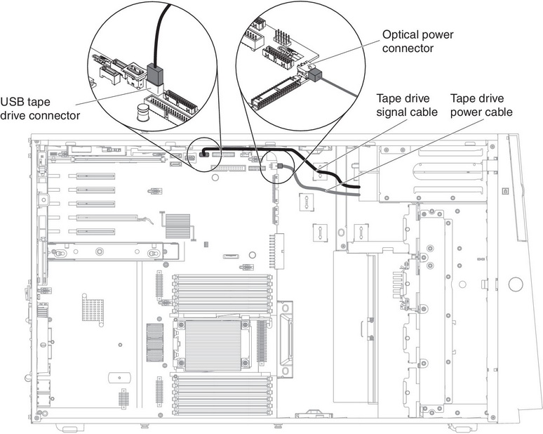
Tape drive cable connection - Lenovo System x3500 M4

Tarp Switch Kit, Rocker (with Solenoid) 5541020 | Buyers Products

Roll Rite Electric Kit With 10698 12V Relay and Rocker Switch
A Further Study of Inconsistencies between Autoignition and ...

Pin on Simpan Cepat

Simple Switch, Motor Reversing Relay & Rocker Switch Kit Assembly, Universal

Wiring Diagrams | Guitar diy, Bass guitar pickups, Guitar tech
SINGLE & DUAL STAGE GANTRY

Diagram of the extracorporeal perfusion system used to study ...
Comments
Post a Comment