43 ethane cracker process flow diagram
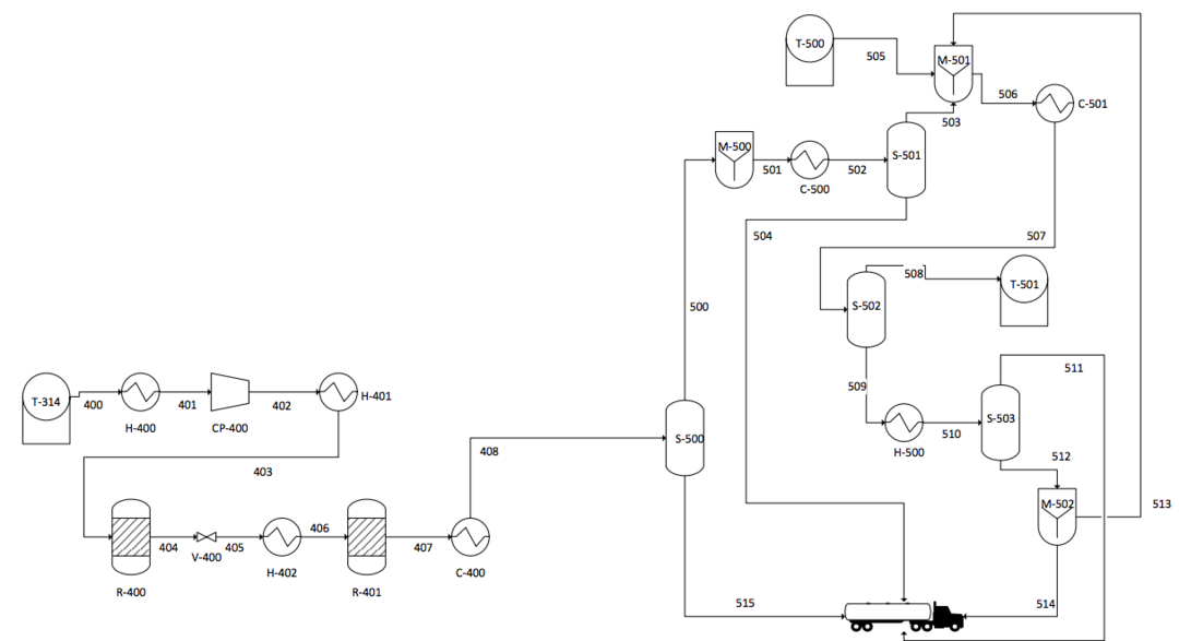
Figure 4 is a process flow diagram for the ethylene plant, which has two board operators using DCS. ... (2011) proposed an MINLP for scheduling of ethylene cracking furnaces system, which can consider the secondary ethane cracking, no simultaneous cleanup constraints and dynamic scheduling. Lummus Technology's proprietary ethylene steam cracking process is the most widely-applied process for the production of polymer grade ethylene, polymer grade propylene and butadiene. The process is noted for its performance, including high product yield and energy-efficiency, low investment cost and operating reliability.
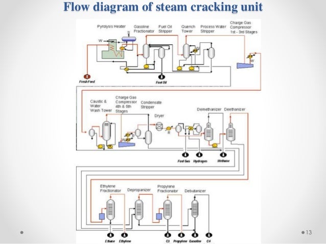
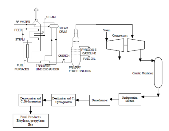
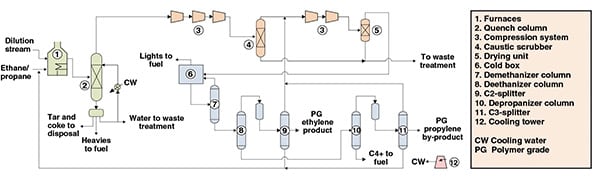
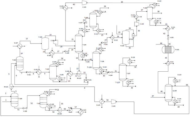
The process shown in Figure 1 is a steam-cracking process for ethylene production from an ethane-propane mixture. The process can be divided into three main parts: cracking and quenching; compression and drying; and separation. Figure 1. This process diagram shows an ethylene-production process via the cracking of an ethane-propane mixture.
Ethane cracker process flow diagram
The model was used to simulate the performance of propane and ethane cracking. The model predicted propane conversion is 95.55 against the plant data of 95% at a coil outlet temperature of 845 °C ... Figure 1.This process diagram shows an ethylene-production process via the cracking of an ethane-propane mixture. This process is divided into three stages such as cracking & cooling, compression & drying and separation. [Figure 1. Ethylene-production process via the cracking of an ethane-propane mixture] Ethane Cracker Flares . Figure C-2: Ethane Cracker Emission Sources ... Figure C-4C: Polyethylene Plant C Process Flow Diagram Product Feeds Vent Streams Recycle Feeds Waste Feeds Oxidizer Feeds Fuel Burning Equipment PM Pollution Control Devices COMONOMER LIQUID WASTE WASTE WAXES PELLET
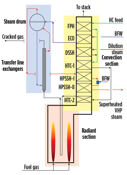
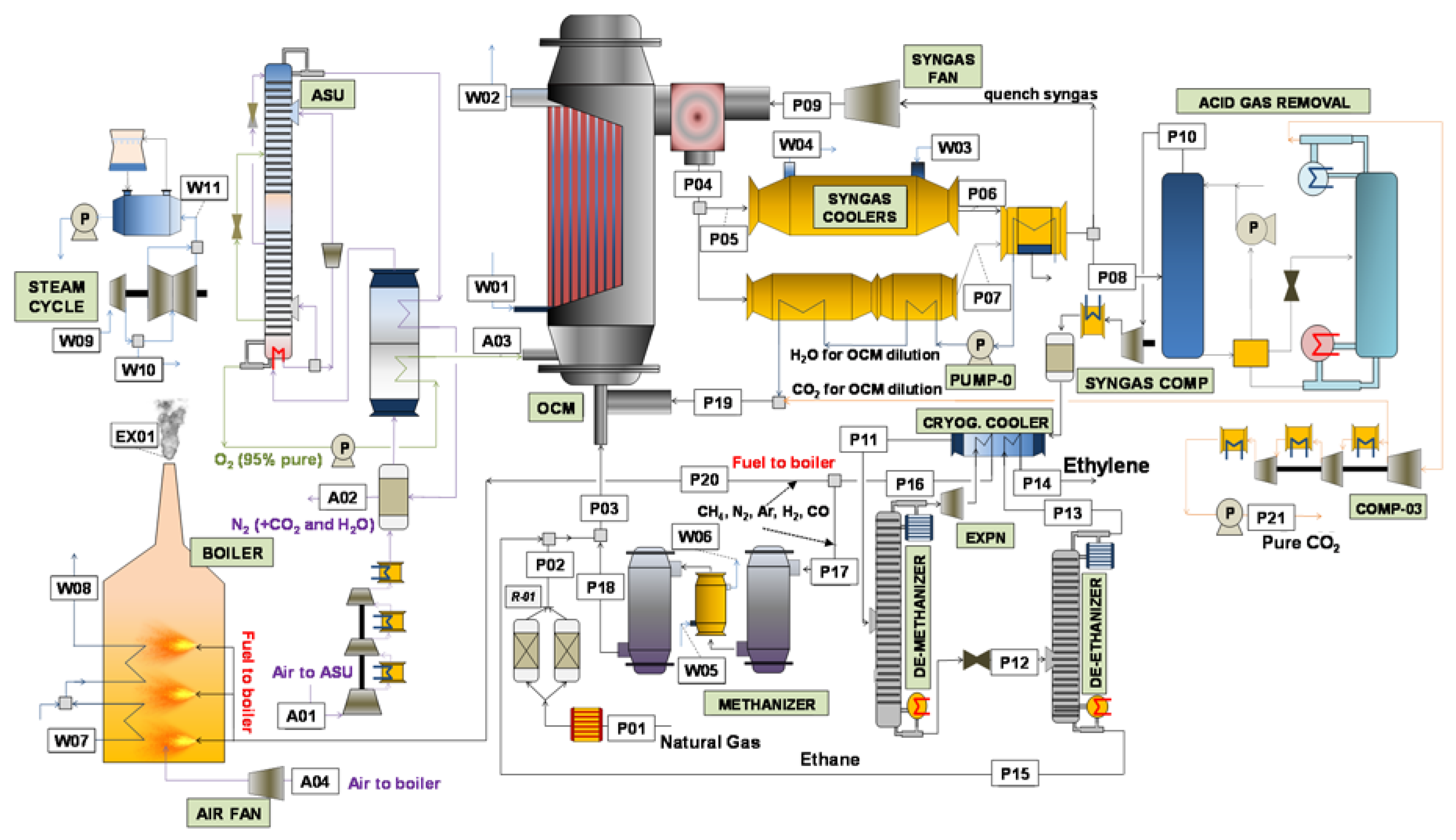
Ethane cracker process flow diagram. of the whole process which, in combination with available OCM reactors, can make this technology a decent choice for commercial ethylene production. The diversity of ethylene plants (naphtha cracking, ethane cracking, coal-to-olefin…) means there is no universally superior option. Finding an application for Advances in Ethane Cracking. Gabriel Castaneda, P.E. Gabchem Solutions. Linde (713) 873 1708. Gabriel@gabcheminc.com Steam cracking furnaces are process units, devoted to producing ethylene and propylene from a stream of light hydrocarbons (e.g., light naphtha) and steam. These massive pieces of equipment are comprised of two key components, namely, a coil bundle, where the cracking reactions take place, and a furnace, which provides heat to the coils (recall that cracking reactions are endothermic). An apparatus and system for the dehydrogenation of ethane to produce ethylene and hydrogen through the use of a catalytic ceramic membrane having selective permeability, thus permitting separation of hydrogen from the reaction zone which causes further dehydrogenation of ethane, the catalytic ceramic membrane being in a cylindrical form which has been treated to have a metallic catalyst of ...
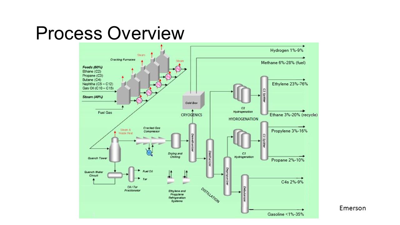
The majority of ethylene is produced using a process called "steam cracking", a thermal process where hydrocarbons are broken down, or "cracked" into smaller molecules that are then used to manufacture more useful (and valuable) chemicals. In the petrochemical industry, two of the main feedstocks for steam crackers are naphtha and ethane. process of ethylene production developed at Texas A&M University to the most common processes. Ethylene is produced commercially using a wide variety of feedstocks ranging from ethane to heavy fuel oils. Of them, the thermal cracking of ethane and propane using a fired tubular heater is the most common process in the United States. In Europe Steam Cracking Process. A typical ethane cracker has several identical pyrolysis furnaces in which fresh ethane feed and recycled ethane are cracked with steam as a diluent. Figure 3-12 is a block diagram for ethylene from ethane. The outlet temperature is usually in the 800°C range. Figure 8: Process flow diagram of ethane steam cracking process.....42 Figure 9: Specific energy consumption of major sections- ethane cracking process.....49 Figure 10: Major energy contributors- ethane cracking process.....50 Figure 11: Block diagram of methane pyrolysis using partial oxidation method of heat ...
with a multitude of applications. Ethylene itself is produced by thermally cracking ethane, a component of natural gas. The Lindgren Group has designed a process capable of producing 500 million pounds of ethylene per year from raw natural gas. Additional products such as interstate The ethane is fed to five cracking furnaces to heat the ethane to cracking temperature. To reduce coke formation in the cracking furnace tubes, a sulfide material is added continuously to the ethane feed. The concentration of sulfide material in the ethane feed is maintained at low ppm levels. A process flow diagram for the Ethane Cracker Plant is presented in Figure 2-1, which outlines all major processes and equipment, including cracking furnaces, a quench tower, a compressor section, a caustic removal section, an ethylene recovery section, and the thermal oxidizer. Ethane Cracker Process Flow Diagram. Here are a number of highest rated Ethane Cracker Process Flow Diagram pictures upon internet. We identified it from trustworthy source. Its submitted by direction in the best field. We take this nice of Ethane Cracker Process Flow Diagram graphic could possibly be the most trending topic afterward we ...
Chap 1
production are naphtha and natural gas (ethane, propane, butane, etc.). The first step in the production of ethylene is to take the feedstock and crack it into ethylene and other various products in a furnace. This process is called pyrolysis. Pyrolysis is the thermal cracking of petroleum hydrocarbons with steam, also called steam cracking.
Triple-lane layout for enhanced cracking coil performance
Figure 15 Block flow diagram for 100% ethane steam cracking 27 Figure 16 Input/output diagram for 100% ethane steam cracking 32 Figure 17 Simplified naphtha steam cracker block flow diagram 34 Figure 18 Coal-to-ethylene simplified block flow diagram 44 Figure 19 Primary forms of commercial coal gasifiers 52
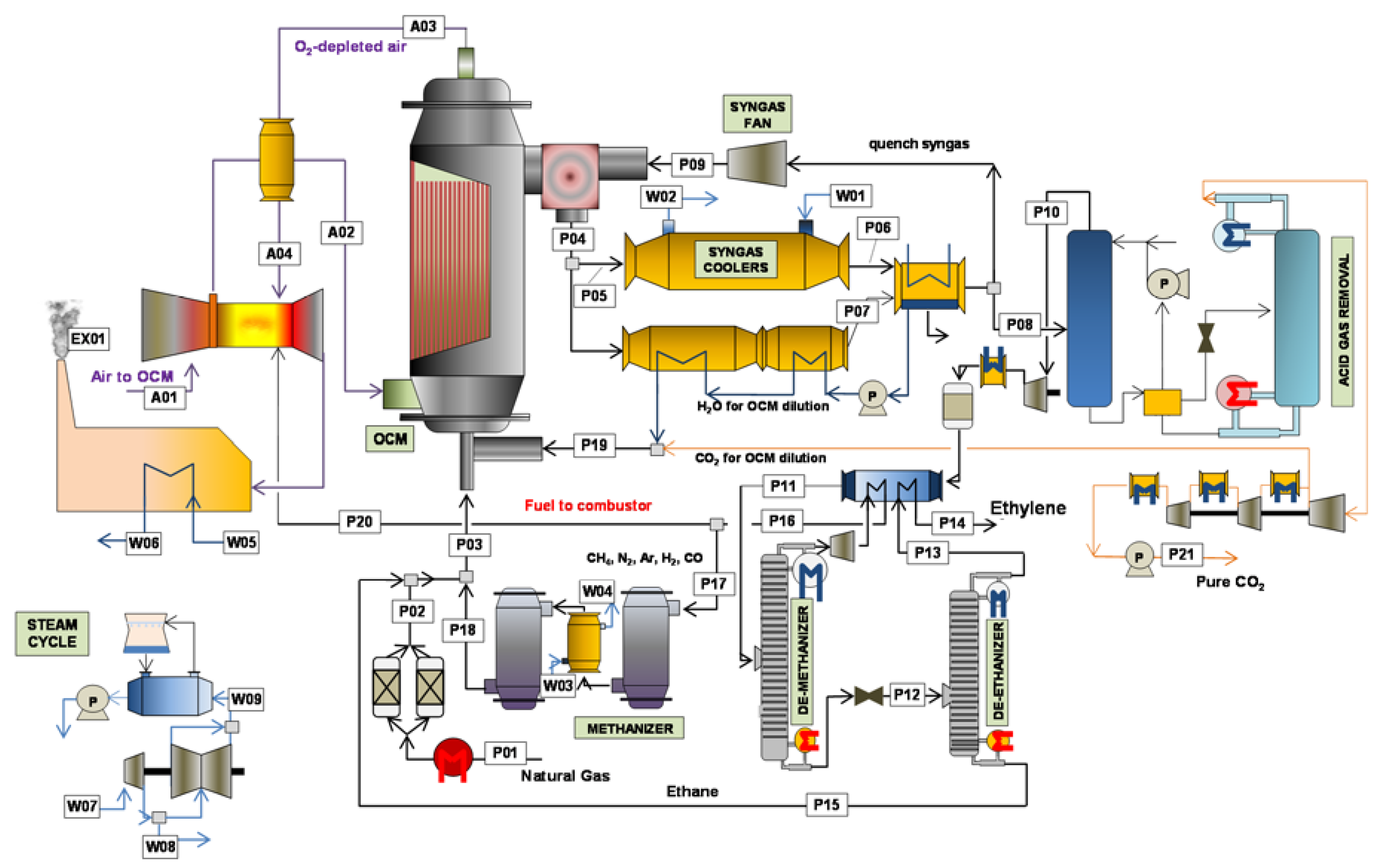
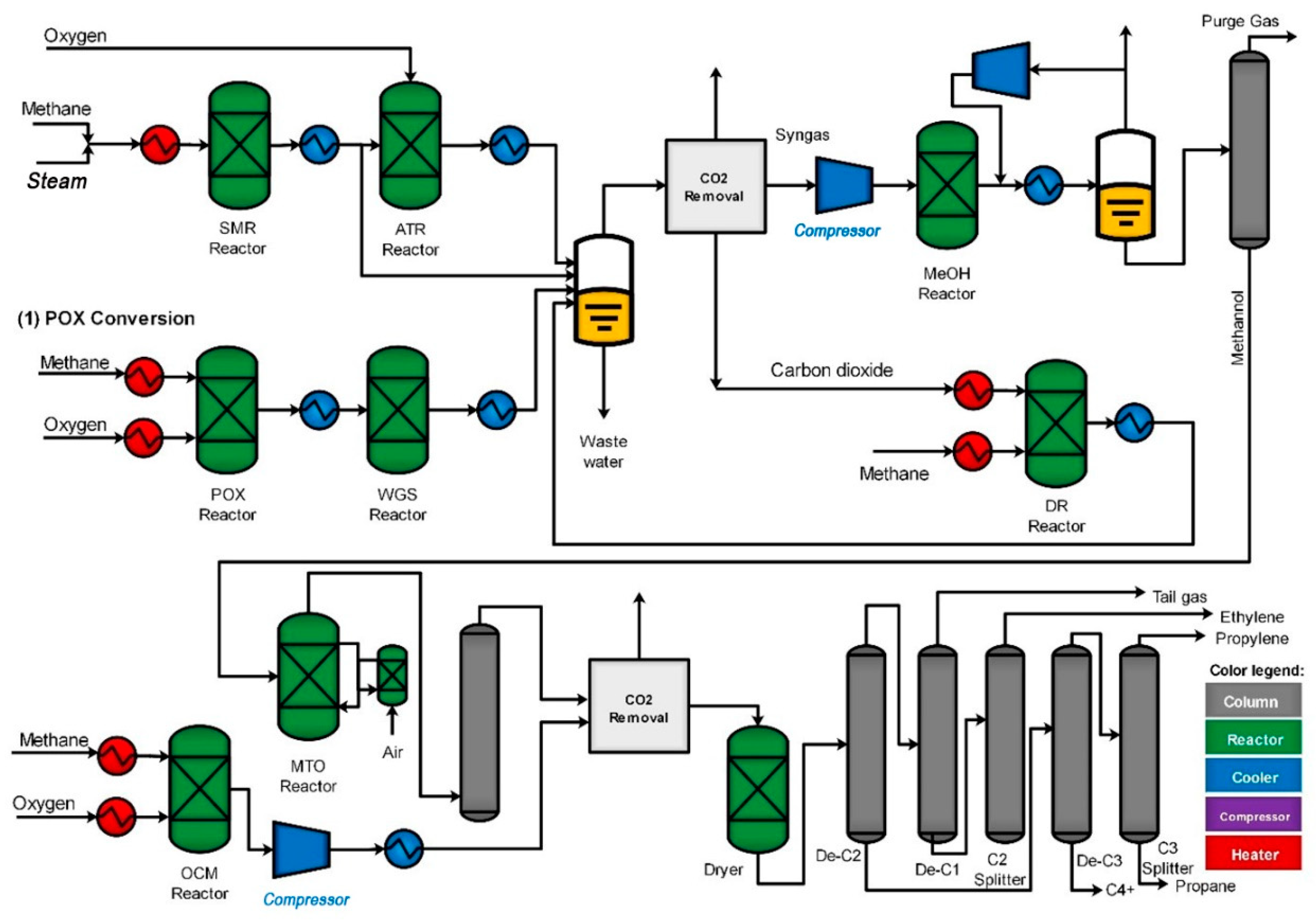
Processes | Free Full-Text | Oxidative Coupling of Methane in ...
For each iteration, the acetylene was hydrogenated, and then 100% of the ethane was recycled. This was repeated until the recycled ethane was extinct. These iterations were performed on Table 2.2: Furnace Product Stream Composition Component Mass Flow Rate (lb/hr) Mass Percent in Stream H 2 2,249 1.6 CH 4 26,409 18.9 C 2H 2 844 0.6 C 2H 4 ...
Hydrogen | Free Full-Text | Techno-Economic Analysis of a ...
Cryogenic distillation columns are then used to isolate methane, ethylene, and ethane from heavier hydrocarbons (C3+). Methane and ethylene are sold as product, and ethane is recycled to the cracking furnace. Natural gas combustion within the furnace raises temperatures high enough to induce the cracking reaction that converts ethane to ethylene.
Comparative Techno-Economic and Environmental Analysis of ...
Ethane Cracker Process Flow Diagram - Wiring Diagram Source A typical process flow diagram (PFD) of such a vacuum distillation column is presented. Light vacuum gas Oil is sent to a hydrotreater and then to a 'catalytic cracking' unit to obtain smaller chain hydrocarbons. Heavy vacuum gas oil is

Typical Process Flow Diagram (PFD) - Pygas Processing ...
2. How does an ethane cracker work? Although other methods exist for "cracking" petrochemicals, thermal cracking by steam is the most commonly employed method for producing ethylene.6 The process may be different at different facilities, but a general ethane steam cracker design involves several common steps.

Techno-economic assessment of different routes for olefins ...
cracking is a mature and optimized industrial process, but remains both capital and energy intensive. Thus, the steam-cracking process is the subject of frequent process-intensification studies to reduce the process-energy demand (Gao et al. 2019). The primary purpose of this report is to present a scaled modeling and

Advances in Ethane Cracking - ppt download
Drawing: Process Flow Diagram.vsd Figure 2-1 Date: November 2012 Simplified Process Flow Diagram ExxonMobil Chemical Company Project No.: 55-2-24 Revision No.: 2 Ethylene Expansion Project FINs: XXAF01 XXABDEC FINs XXEF01 XXEFDEC FINs XXFF01 XXEFDEC FINs XXGF01 XXGHDEC FINs XXHF01 XXGHDEC Quench Tower Caustic Wash and Compression EPN XXAF01-ST ...
Process economics and safety considerations for the oxidative ...
The proposed design consists of six main sections: acid gas removal, dehydration, fractionation train, hydrogenation reactor, an ethylene splitter and steam cracking (refer to Appendix B for the process flow diagram). Carbon dioxide must first be removed from the inlet shale gas in the acid gas removal section.
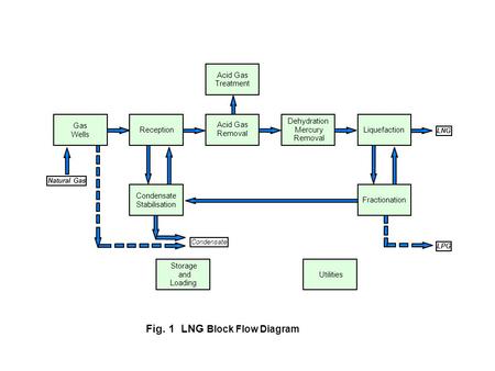
Chemicals from Natural Gas and Coal | SpringerLink
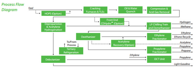
Process flow diagram for ethane crackers (areas in red are not needed in ethane plants) ... Light olefins are conventionally produced by the steam cracking of hydrocarbons from ethane to gas oil ...
Process Design and Analysis of Ethylene and Propylene ...
Ethane Cracker Flares . Figure C-2: Ethane Cracker Emission Sources ... Figure C-4C: Polyethylene Plant C Process Flow Diagram Product Feeds Vent Streams Recycle Feeds Waste Feeds Oxidizer Feeds Fuel Burning Equipment PM Pollution Control Devices COMONOMER LIQUID WASTE WASTE WAXES PELLET

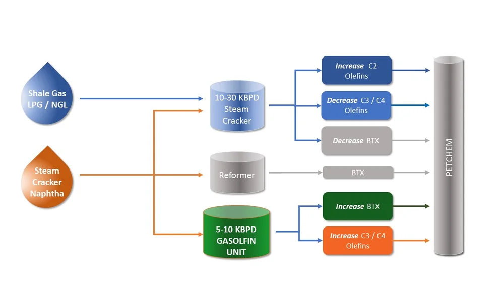
Propylene Maximization in the Downstream Industry – Available ...
Figure 1.This process diagram shows an ethylene-production process via the cracking of an ethane-propane mixture. This process is divided into three stages such as cracking & cooling, compression & drying and separation. [Figure 1. Ethylene-production process via the cracking of an ethane-propane mixture]

Flare minimization practices improve olefins plant start-ups ...
The model was used to simulate the performance of propane and ethane cracking. The model predicted propane conversion is 95.55 against the plant data of 95% at a coil outlet temperature of 845 °C ...

Ethylene | Toyo Engineering Corporation
04 petrochemical precursor ethylene and propylene
Biomass to Ethylene (B2) - processdesign
Lecture 13: Petrochemicals: Overview
Is US Plastic Production Going Domestic? | Engineering.com
Oil refinery/petrochemical integration in a CO2
Processes | Free Full-Text | Oxidative Coupling of Methane in ...
New Catalytic Process for Production of Olefins - Oil&Gas Portal
Industrial Feedstock Chemicals
Petrochemical application — INOVACAT
Chap 1
![Natural Gas to Olefins, Symposium[2]](https://image.slidesharecdn.com/0b411131-d6a1-4822-ad58-dbcc1933154c-150612193624-lva1-app6891/85/natural-gas-to-olefins-symposium2-18-320.jpg?cb=1434137873)
Natural Gas to Olefins, Symposium[2]
Advances in Ethane Cracking - ppt download
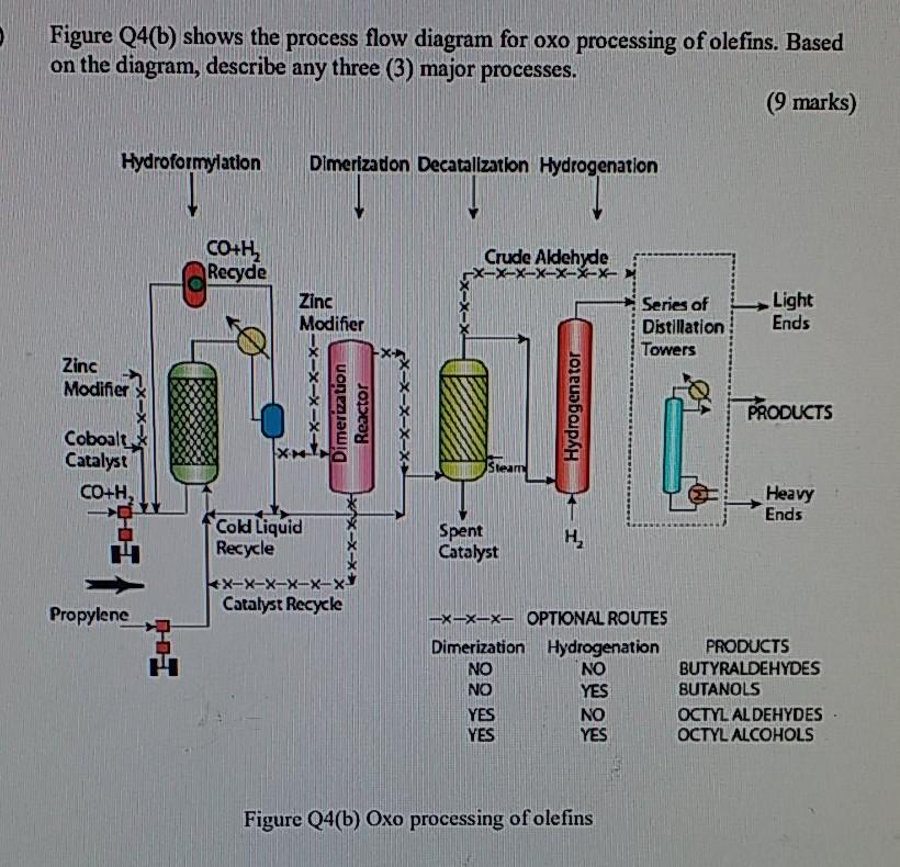
Solved Figure Q4(6) shows the process flow diagram for oxo ...
Evolution of a digital twin with an ethylene plant as an ...
Advances in Ethane Cracking - ppt download

Butadiene – 2B1stconsulting
Olefin Production from Heavy Liquid Hydrocarbon Thermal ...

Mathematical Modeling of Ethane Cracking Furnace of Olefin ...

Deciphering the true life cycle environmental impacts and ...

Hydrodesulfurization - Wikipedia

Cracking (chemistry) - Wikipedia
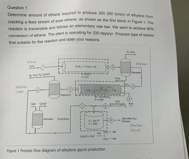
Question 1 Determine amount of ethane required to | Chegg.com

Steam Cracker – Take it to the top !

1. Simplified flow scheme of a naphtha cracker | Download ...
Ethylene Production via Cracking of Ethane-Propane - Chemical ...

Ethylene Plant - an overview | ScienceDirect Topics
Shale Gas to Ethylene (G2) - processdesign

Simplified PFD of the Cracking Process 1. Cracking units ...
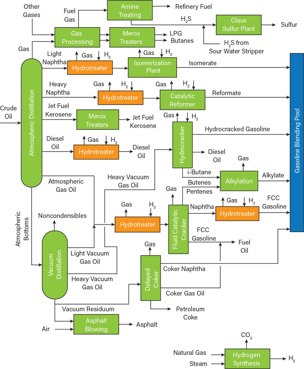
An Overview of Hydrotreating | AIChE
Comments
Post a Comment