42 hid ballast wiring diagram
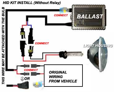
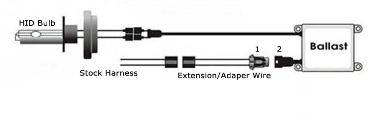
The wiring diagram is the blueprint for the ballast circuitry, including the input supply voltage and grounding methods. A ground connection must be made to all ballasts to avoid shock hazard, personal injury or damage to the luminaire or installation. Ballast installations and groundings should be made in accordance with all applicable ... The HID lights are the nearest to daylight in terms of brightness. Wiring the ballast for Xenon HID light is a bit more intricate than wiring of normal halogen bulbs of the automobile headlights. With these ballasts you save electrical energy as the power consumption on HID bulbs is much lower. The wiring diagram includes the details of ...
Standard Wiring Diagram IOAmp Wire ... Ballast Control Wire Hi/Lo Bulb to G or Battery -s to G or Battery to factory headlight soc ket 20A Fuse to . HID lbs 23000 V ...
Hid ballast wiring diagram
All Multi-5 ballasts voltage (120V, 208V, 240V, 277V, & 480V) Wiring Diagrams Reference Diagrams Pulse Start Metal Halide Catalog Number Wattage Reference Diagram Wiring Diagram P250ML5AC4E* 250 PC2 2 P320ML5AC4E* 320 PC2 2 P400ML5AC4E* 400 PC2 2 P750ML5AC5E* 750 PC3 2 P1000ML5AC5E* 1000 PC3 2 Metal Halide According to earlier, the lines at a Hid Wiring Diagram represents wires. Sometimes, the cables will cross. But, it doesn’t mean connection between the wires. Injunction of 2 wires is generally indicated by black dot in the junction of 2 lines. There will be principal lines which are represented by L1, L2, L3, and so on. Easy Access WIRING DIAGRAM. HID KITS.The mercury vapor ballast wiring diagram is the blueprint for the ballast circuitry, including the input supply voltage and grounding methods. A ground connection must be made to all ballasts to avoid shock hazard, personal injury or damage to the luminaire or installation.
Hid ballast wiring diagram. 2. Hella lighting has a variety wiring harnesses for the Rallye , Xenon, High performance and FF Series lamps. Making wiring easy with these kits. All harnesses include a switch and necessary connectors for plug and play installation. Find great deals on eBay for hella hid ballast. Shop with confidence. HID ballasts: Magnetic ballast. >. cwa-metal-halide-ballast-manufacturer. The mercury vapor ballast wiring diagram is the blueprint for the ballast circuitry, including the input supply voltage and grounding methods. A ground connection must be made to all ballasts to avoid shock hazard, personal injury or damage to the luminaire or installation. ballast wiring diagram - You will need a comprehensive, professional, and easy to comprehend Wiring Diagram. With such an illustrative guide, you will be able to troubleshoot, avoid, and complete your projects easily. Not only will it assist you to attain your desired outcomes quicker, but in addition make the complete procedure simpler for everybody. Hid Ballast Wiring Diagrams For Metal Halide And High Pressure throughout 480V To 120V Transformer Wiring Diagram by admin Through the thousand photos online regarding 480v to 120v transformer wiring diagram, we all picks the top libraries using ideal quality simply for you, and this photographs is actually one of graphics series within our greatest photographs gallery in relation to 480V To ...
Hid wiring harness diagram. The following manual contains detail explanation on how to install the hid xenon headlight conversion kit from jem automotive and its wiring harness this conversion kits contents of 2 xenon hid bulbs 2 ballasts ballast mounting brackets 1 heavy duty wiring harness with relays mounting nuts bolts and washers. An HID ballast (HID stands for High-Intensity Discharge) is a device that is used to control the voltage and arc current of High-Intensity Discharge lamps during their operation. The circuit diagram for the various types of HID ballasts is shown below. Types of HID Ballast HID ballasts can be classified into four different categories/types: HID Ballast Wiring Diagrams for HID ballast kits including Metal Halide and High Pressure Sodium Lighting ballasts. Most magnetic HID ballasts are multi-tap ... Instant start ballasts can only be wired in parallel according to the diagram on the ballast. Changing the wiring on a fluorescent light fixture from rapid start to instant start, involves changing the wiring from series to parallel. 1 Lamp Rapid Start Ballast Diagram.
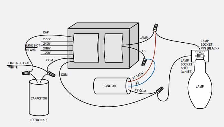
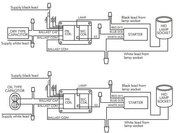
Ballast Wiring Diagrams for HID ballast kits including Metal Halide and High Pressure Sodium Lighting ballasts. Most magnetic HID ballasts are multi-tap, ... PIB - HID Fixture Wiring Instructions Specifications subject to change without notice. HID Ballast Wiring Connections TYPICAL REACTOR WIRING CONNECTIONS (for HI reactor ballasts with model number –1xx suffix, such as S0150-02C-111) 1. Field wiring connections should only be made by qualified personnel. 2. Locate the wire on your transformer with the word cap, connect it to your Venture Lighting: Additional Ballast Lighting Diagrams. Ballast Wiring Diagrams for HID ballast kits including Metal Halide and High Pressure Sodium Lighting ballasts. Most magnetic HID ballasts are. BALLAST. RED. RED. LINE. WHITE. BLACK. BLUE. BLUE. YELLOW. YELLOW. Most magnetic HID ballasts are multi-tap, meaning they can be connected to several different voltages. Here we display wiring diagrams for metal halide (probe ...
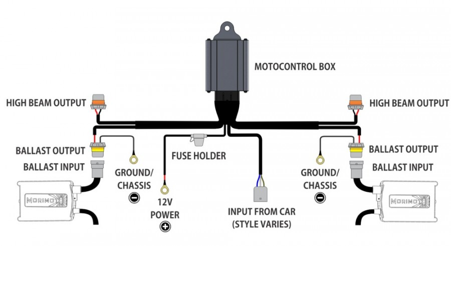
Morimoto H4 9003 Hi/Lo MotoControl Bi-Xenon Wiring Harness
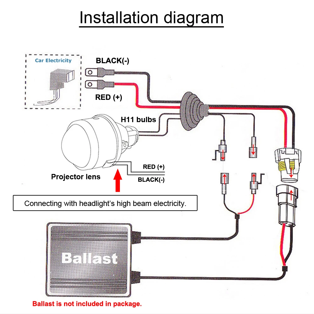
4. Connect the HID bulbs to the ballast (2 round quick-disconnects) 5. Connect the high beam control wires (small rectangular connectors) 6. Connect the ballasts to the Hi/Lo wiring harness (oval connectors with yellow rubber seals) 7. Connect the 3-pin socket on the wiring harness to ONE of the headlight sockets 8.

DZG HID Relay Harness 12V HID Wiring Universal Relay Wiring ...
Diagram ballast wiring diagram for hid lighting full version. A wiring diagram is a simplified standard photographic depiction of an electric circuit. If a diagram cannot be found within. Tube Light connection diagram shown here is suitable for common type fluorescent tubelight.

INSTALLATION GUIDE
ULTRA ELECTRONIC BALLAST ULTRA MAX ELECTRONIC BALLAST MAX ULTRAMAX ULTRAMAX ELECTRONIC BALLASTS TM ELECTRONIC BALLASTS 1-6 transforming the power of light™ For more information, visit www.gelighting.com 1-7 CHOOSING THE RIGHT BALLAST IS SIMPLE. The easy-to-understand model numbering system helps you choose and install the right model.

INSTALLATION GUIDE
Hella Hid Ballast Light Wiring Diagram I have a used hella ballast off a 02 Mercedes ML with Bi-xenon and the If I want test this ballast did anyone know the wiring diagram?. Connect the bulbs to the ballast harness making sure the safety clips on the connectors are fully Fitting a HID kit internally to a Hella Rallye driving light.

12V Automobiles 35W Universal Cars Xenon HID 55W Ballast ...
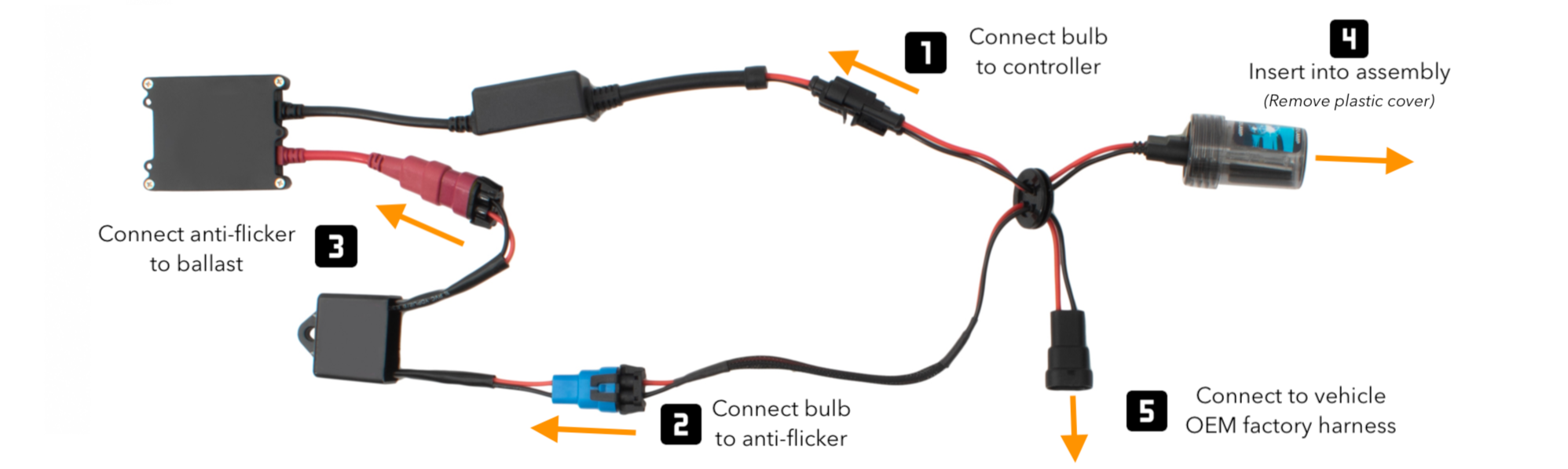
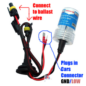
Connect all the plugs from the ballast to the bulb as shown in the diagrams. Ensure that you get the polarity correct. HID lights do not work with reversed polarity. Make sure that the plugs are securely placed and firmly intact. If you have a bi-xenon kit, connect the ballasts to the relay harness.
9006 Xenon HID Headlight Bulb - Installation Guide - XenonPro.com
The wiring diagram is the blueprint for the ballast circuitry, including the input supply voltage and grounding methods. A ground connection must be made to all ballasts to avoid shock hazard, personal injury or damage to the luminaire or installation.
HID Kit Installation Guide - CarHIDkits
Changing the wiring on a fluorescent light fixture from rapid start to instant start involves. View the wiring diagrams for ballasts 10-0091 10-0127 10-0136 10-0137 10-0155 10-0201 10-0210 below or download a PDF ballast specification sheet which includes the ballast specs photos lamp types and wiring diagrams.

DZG HID Relay Harness 12V HID Wiring Universal Relay Wiring ...
Ballast Wiring Diagrams for HID ballast kits including Metal Halide and High Pressure Sodium Lighting ballasts. Most magnetic HID ballasts are multi-tap, ...
HID Conversion Kit Installation Guide — iJDMTOY.com
Hid Ballast Wiring Diagrams For Metal Halide And High Pressure Sodium Ballasts Ballast High Pressure Sodium Lights Diagram . Troubleshooting Problem Wiring Power Gt Two Fluorescent Ballasts Wire Light Fixture Wire Lights Fluorescent Light Fixture . Pin On Duraspark Wiring .

Ballasts
Wiring Instructions Disconnect All Power Double-End Power Tube (Ballast Bypass) 1.) IMPORTANT: The below ballast wiring diagrams represent a typical configuration. Actual ballast wiring varies according to the ballast model.
TAOCHIS M6 2.0 Inch Bi Xenon HID Auto Car Styling Fog Light ...
In this video I will show you how to install a relay wiring harness for your HID lighting system. This type of relay wiring harness is common with most insta...

philips electronic ballast wiring diagram, philips electronic ...
Ballast Wiring Diagrams for HID ballast kits including Metal Halide and High Pressure Sodium Lighting ballasts. Most magnetic HID ballasts are multi-tap, meaning they can be connected to several different voltages. Here we display wiring diagrams for metal halide (probe start), metal halide (pulse start) and high pressure sodium HID ballast kits.

How to Install a Dual Beam HID / Bi-Xenon HID Conversion Kit Relay Harness
Open the back cap of the headlight assembly and take out the stock bulb.H13 Plug - Wiring Diagram September 6, Scott Xenon 2 Comments bixenon instructions, h13 installation, h13 plug wiring diagram, hid install, hid wiring More and more, H13 Bi-xenon bulbs are being used in automotive applications.

30 Unique Hid Headlight Relay Wiring Diagram | Electrical ...
About Press Copyright Contact us Creators Advertise Developers Terms Privacy Policy & Safety How YouTube works Test new features Press Copyright Contact us Creators ...

Replacement Xenon Hid Ballast For D1S D1R Bulbs Lighting Lamp Part Gas Discharge
wiring diagrams hid ballast kit wiring diagrams magnetic fluorescent ballast wiring diagrams 1 - low watt mh/hps qv 2 - 175-1500w mh qv 1 - rapid start 2 - slimline 120v 3 - low watt hps 4 - 250-1000w hps qv 3 - slimline 277v 4 - high output 5 - 150-250w mh 480v 6 - 250-1000w hps 480v electronic ballast wiring diagrams 1 - t5 2 lamp 2 - t5 4 lamp

04-05 GSXR600 HID Kit Install - Morimoto H7 Lo-beam single ...
Easy Access WIRING DIAGRAM. HID KITS.The mercury vapor ballast wiring diagram is the blueprint for the ballast circuitry, including the input supply voltage and grounding methods. A ground connection must be made to all ballasts to avoid shock hazard, personal injury or damage to the luminaire or installation.

HYB H11 6000K HID Blub Xenon Headlight Replacement Bulbs H8 ...
According to earlier, the lines at a Hid Wiring Diagram represents wires. Sometimes, the cables will cross. But, it doesn’t mean connection between the wires. Injunction of 2 wires is generally indicated by black dot in the junction of 2 lines. There will be principal lines which are represented by L1, L2, L3, and so on.

Wrdlosy 2PCS HID Ballast, DC 12V 55W Super Slim Hid Ballast Ballast Kit for H1 H3 H7 H8 H9 H11 9005 9006 H4
All Multi-5 ballasts voltage (120V, 208V, 240V, 277V, & 480V) Wiring Diagrams Reference Diagrams Pulse Start Metal Halide Catalog Number Wattage Reference Diagram Wiring Diagram P250ML5AC4E* 250 PC2 2 P320ML5AC4E* 320 PC2 2 P400ML5AC4E* 400 PC2 2 P750ML5AC5E* 750 PC3 2 P1000ML5AC5E* 1000 PC3 2 Metal Halide
☆Fast Local Delivery☆HID Xenon 12V Ballast 55W/35W ...

one.D'RIVE: How to install H7 HID conversion kit on Peugeot 308

How to wire Xenon HID ballast
To those who installed an HID Kit, where did you put your ...
Xenon Hid Kit Sale,3300lumen 35w.55w.70w.100w 12-24v Xenon ...

Buy AC Canbus HID Ballast, Xenon Ballasts Control Unit with ...

I have a 04 escalade with DR1 HID lights. the ballasts are ...
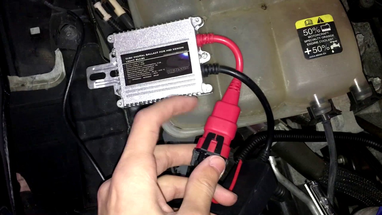
How to install a HID ballast
H4 HARNESS H4 HID SOCKET RELAY WIRING HARNESS HID H4 XENON LIGHT SYSTEM RELAY HARNESS FOR HI/LO
How to install a HID ballast
How to Install HID Headlights with Relay Harness

INSTALLATION GUIDE
HID Ballast Wiring Connections
HID Kit Installation Guide - CarHIDkits
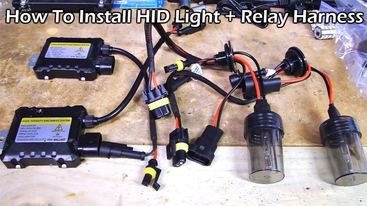
How To Install HID Light with Relay Wiring Harness

Wiring Query: Grow Room HID HPS Lamp & Ballast Installation ...

HID Kit DIY Installation Guide - Redline360

35 Watt HID Wiring | Basic wiring diagram to convert a stand ...

Electronic HID Ballast 0-10v Dimmer | All About Circuits

Universal HID Conversion Kit Single Beam Relay Resistor Harness

hid ballast quick question - Honda-Tech - Honda Forum Discussion
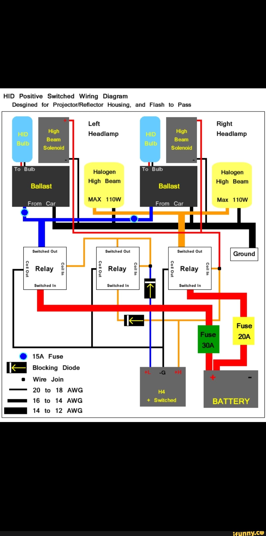
HID Positive Switched Wiring Diagram Desgined for Housing ...
.jpg)
Creating an HID Ballast with Constant Lamp Power Control ...

Buy 12V 55W H1 4300K Heavy Duty AC HID Xenon Bulbs bundle ...
Comments
Post a Comment