42 fuel injection system diagram
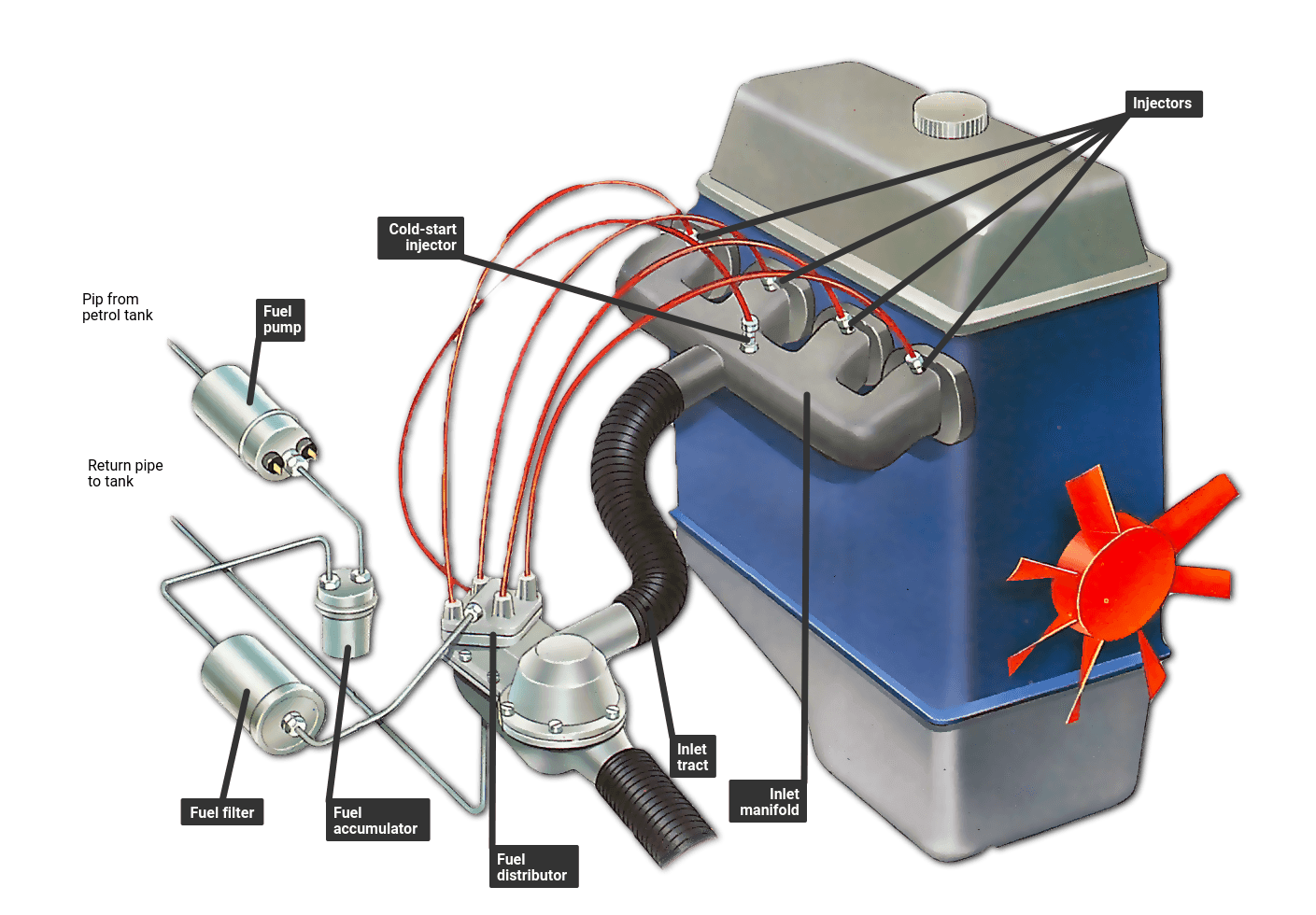
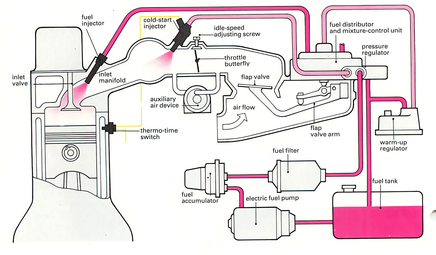
There are basis principles of K Jetronic system working are continuous fuel injection and direct air flow measurement. This mechanical system does not include an engine-driven fuel pump. The main goal of K Jetronic system is to continuously meter fuel in proportion to the amount of air at the intake stroke. Technical paper describing basic components of diesel fuel injection systems, including fuel pumps, filters, fuel injectors and fuel injector nozzles [DieselNet Technology Guide].
For an excellent in-depth discussion on the workings of the Fuel-Injection System in the 3.0l V6, refer to John Parkinson's three- part series for the Mitsubishi 4WD Owner's Club of Queensland: Pajero V6 Fuel-Injection Systems.

Fuel injection system diagram
Fuel Injection Fuel Feed Line, Front, RH, Distribution Block To Feed Rail. Have Chevy lb7 duramax need a diagram of fuel lines in filter housing or the whole fuel system got some mixed up - Answered by a. Have Chevy lb7 duramax need a diagram of fuel lines in filter housing or the whole fuel system got some mixed up - Answered by a. The main components of the fuel system in diesel engine are: (1) fuel filter (2) fuel lift pump (3) fuel injection pump (4) atomisers and (5) high pressure pipe. → Flow diagram of fuel in diesel tractor Cylinder Injector Fuel Diesel Tank Fuel Filter lift pump Filter Fuel injection pump → → → ↑ ← Components of the fuel system. Understanding the basic layout of a fuel system, additional components make the mechanical fuel injection system useful. A barrel valve or metering valve controls the appropriate amount of fuel for starting, part-throttle, driving, and stopping. A barrel valve is also used to throttle the fuel for part-throttle ...
Fuel injection system diagram. Fuel System Diagram. The fuel system diagram provides a simplified view on how fuel flows within an EFI system. The fuel tank supplies gasoline to the fuel pump. The fuel pump can be located in the fuel tank or external to the tank. ... With a fuel injection system, the fuel map must be altered to reflect changes in airflow at various engine ... valve. The GDI fuel rail system is able to pressurize the fuel rail up to 250 bar. The fuel rail pressure is independent of the engine speed; see Figure 2 for the system block diagram. Pump Motor Fuel Tank w/ Low Pressure Pump (~30PSI) Fuel Rail Relief Valve Figure 2: Fuel Rail System Block Diagram May 26, 2021 - Looking for an aftermarket EFI system? Our team of experts narrowed down the best aftermarket EFI systems on the market. Read this review and save yourself time and money. For the engine to run smoothly and efficiently it needs to be provided with the right quantity of fuel/air mixture according to its wide range of demands. Traditionally, the fuel/air mixture is controlled by the carburettor, an instrument that is by no means perfect. Many diesel engines, however, use direct injection in which the diesel is injected directly into the cylinder filled with compressed air. Others use indirect injection in which the diesel fuel is injected into the specially shaped pre-combustion chamber which has a narrow passage connecting it to the cylinder head. Only air is drawn into the cylinder. It is heated so much by compression that atomized fuel injected at the end of the compression stroke self-ignites. All modern petrol injection systems use indirect injection. A special pump sends the fuel under pressure from the fuel tank to the engine bay where, still under pressure, it is distributed individually to each cylinder. Depending on the particular system, the fuel is fired into either t
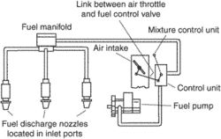
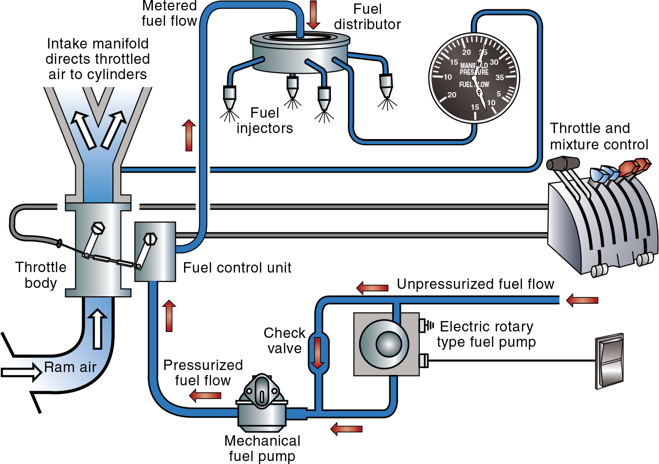
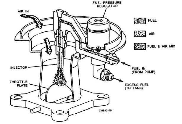
Download scientific diagram | Schematic of a Port Fuel Injector [1] from publication: Experimental Study of Injection Characteristics of a Multi-hole port injector on various Fuel Injection pressures and Temperatures | The structures of the port injector spray dominates the mixture preparation ... Fuel System Diagrams - Aeromotive, Inc. Select CARB or EFI Carbureted Fuel Injected. Select Power Adder No - Naturally Aspirated Yes - Forced Induction. Select FUEL Gas E85. Mounting Configuration External In Tank. Step 1: Fill out pump finder above. Step 2: Add the pump to your cart. Step 3: Refer to the diagram on the product page for plumbing or refer back to this page and click the link to your fuel pump diagram. The Continental fuel-injection system injects fuel into the intake valve port in each cylinder head. [Figure 10] The system consists of a fuel injector pump, a control unit, a fuel manifold, and a fuel discharge nozzle. It is a continuous-flow type, which controls fuel flow to match engine airflow. Injector Circuit & Wiring DiagramAmazon Printed Bookshttps://www.createspace.com/3623928Amazon Kindle Editionhttp://www.amazon.com/Automotive-Electronic-Diag...
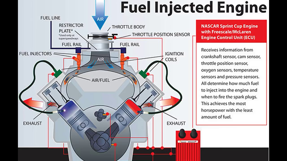
Fuel System: Review of a gasoline carburetor system will aid in understanding the ZEEMS fuel system operation. Carburetors, mechanical fuel injection systems and electronic fuel injection systems all perform the same basic functions; however, the methods incorporated to perform these functions differ. The fundamental purpose of any The block diagram of the Fuel Injection System is as shown in the Fig. 3. The time constraints of the system are imposed by the characteristics of the internal combustion engine to be controlled. It is defined that a turn of the engine i.e. 360° is completed once in every 5 micro seconds for 12,000 rpm. Fuel Injector Control Module Coil Distributor First, the "big picture" block diagram. The components you will see on the left are sensors, or inputs into the ECM. The components on the right are controlled by the ECM based on the inputs it receives from the sensors. THE New Standard in Fuel Injection! Street to Race - From GM's factory COPO Camaro to NASCAR to your car!
Multi-point injection - function, components, working ...
FiTech Fuel Injection TM Instruction Manual for the following Go EFI Systems , , , , , & This Quick Start Manual is designed to get you up and. Apr 27, · thoughts on FITECH EFI The distributor wires connect into the crank sensor wires shown on the wiring diagram. The fuel rails shown in the list are Edelbrock parts designed to fit a Victor EFI ...
What does "injection style" mean?
21. mar. 2017 ... Fuel injection is done with the help of cams and camshaft. The speed of the cam shaft is same as the engine speed in a two stroke engine and ...

Electronic Fuel Injection System (EFI) - Architecture, Types ...
June 24, 2019 - Following is the schematic representation of a Fuel Injection System. Schematic diagram of Fuel Injection system in diesel engine

What You Need To Know About Mechanical Fuel Injection
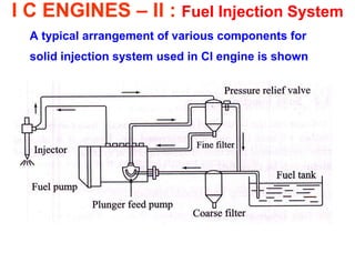
Fuel will flow either because of gravity or fuel feed pump, which is provided to supply fuel through the filter to the injection pump. Which pumps the fuel to the injectors which are provided in the cylinder heads. The fuel injection systems are of 2 types: 1. Air Injection System: In this case fuel is injected under the pressure of air.
INJECTION SYSTEM: COMPONENTS, TYPES AND WORKING PRINCIPLES ...
All internal combustion engines require air, fuel and a spark to run. The fuel system is vital in storing and delivering the gasoline, or diesel, that an engine needs to run. Although fuel systems vary depending on vehicle model, their func...

Electronic Fuel Injection System Diagram and Working ...
Electronic Fuel Injection System Diagram and Working Principle. The electronic fuel injection system is a new innovation in gasoline engine, this system incorporates electronic computerizm to get the best fuel and air comparisons under all engine conditions. The EFI system basically has the same diagrams as conventional fuel systems.
Electronic Fuel Injection Systems for Heavy-Duty Engines
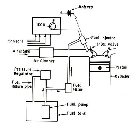
The system controller, adjusts when and how long the injector opens. Fuel injection system working diagram When we start the engine, the fuel pump will work so that the pressure fuel in the fuel hoses increases. Advertisement Here, there is a flow of fuel from the tank to the fuel pump and towards the injector.

Modeling and control of a novel pressure regulation mechanism ...
In Part One, we extolled the virtues The Chevrolet Ramjet Fuel Injection System, which is being reproduced by Corvette America. (Route 322, Box 427, Dept. VM, Boalsburg, PA 16827; 800/458-3475 ...
Electronic fuel injection | Article about Electronic fuel ...
May 16, 2013 - The diagram above shows the how the fuel injection components fit together. This is typical of most fuel injection systems. Usually off-road fuel injection systems will not use an oxygen sensor.

An Overview of Fuel Injection System - Engine Man
We believe the fuel injection system on a diesel is home to the most complex components in your diesel engine. Improper parts, maintenance and care of your fuel injection system can cause complete failure! Here in the B&J Auto Parts we offer more than parts, we offer our deep knowledge
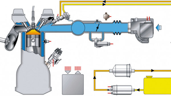
Jetronic fuel injection system - K-Jetronic, KE-Jetronic - MLFREE
Common rail direct fuel injection is a direct fuel injection system for petrol ... 96 Camry Fuel Pump Wiring Diagram Wiring Wiring Diagrams Instructions.

Distributor Injection System
Download scientific diagram | Block diagram of electronic fuel injection system. from publication: An Empirical Study of SysML in the Modeling of Embedded Systems | The complexity increase and variety of equipments controlled by embedded computers generate the need of a multidisciplinary approach ...
Aircraft Systems: Fuel Injection Systems – Learn to Fly Blog ...
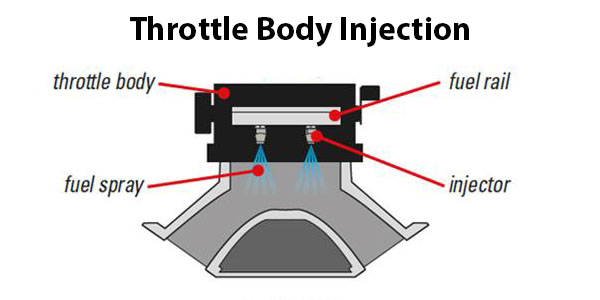
September 1, 2016 - The earliest and simplest type ... with one or two fuel-injector nozzles in the throttle body, which is the throat of the engine’s air intake manifold. For some automakers, single-point injection was a stepping stone to the more complex multipoint system....
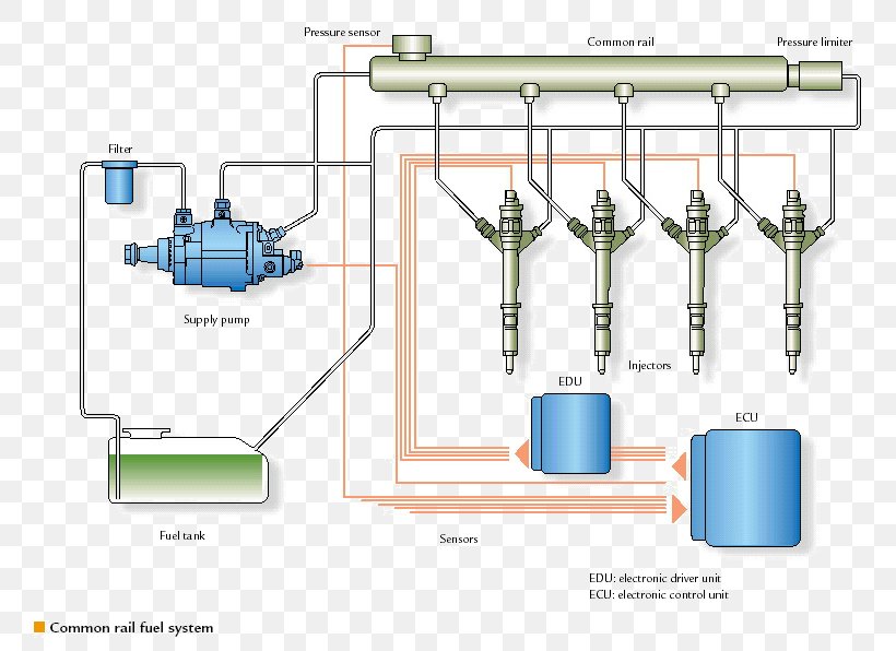
Common Rail Fuel Injection
Apr 10, 2019 - Power Score: Tyranny of Dragons - A Guide to Hoard of the Dragon Queen and The Rise of Tiamat
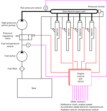
Common rail - Wikipedia
Fuel injector; - The fuel injector acts as the fuel dispensing nozzle. It injects liquid fuel directly into the engine's air stream. The injection is controlled by the ECU. It determines the amount of fuel to injected and in some system if the engine is cold, turns on an "extra" injector which only works while the system is cold.

IHET1234 - Diesel Fuel Injection Systems, Module 190203e ...
Diagram of Multi Point Fuel Injection System (MPFI) Why Multi Point Fuel Injection System (MPFI): Multi-Point Fuel Injection System aka the MPFI system was originally only developed for the airplane engines. Nowadays, it is widely used in light commercial vehicles. MPFI system is the most advanced gasoline injection system the automobile ...

Diesel Engine In-Line Injection System - MATLAB & Simulink
Digifant fuel and ignition control system. Digifant is a development of the Digi-Jet fuel injection system combined with the map controlled digital ignition system. Through the use of a single control unit, all of the functions of the fuel system, ignition system and oxygen sensor system are carefully controlled to
Working of EFI(electronic fuel injection system) | by ...
Figure 1 is a simplified diagram of the entire fuel injection system; refer to it for the following descriptions. Figures 2 and 3 are electrical diagrams which may be helpful when troubleshooting. Air System Components of the air system are shown in Figure 4.

Diesel Engine Fuel Injection System - YouTube
Multiport Fuel Injection Multiport injection systems fire the injectors in groups. A four-cylinder engine may fire the #1 and the #3 injectors on the first crankshaft revolution and then fire the #2 and #4 on the second revolution. A six-cylinder engine would fire three injectors on the first revolution and then fire the other three on the next.
Throttle Body Injection System
The main difference between Carburetor and Fuel injection system {CarburetorzFuel is atomized by processes relying on the air speed greater than fuel speed at the fuel nozzle, zThe amount of fuel drawn into the engine depends upon the air velocity in the venturi {Fuel Injection SystemzThe fuel speed at the point of delivery is greater than the air speed to atomize the fuel.

Download this stock vector: Common rail direct fuel injection ...
Download scientific diagram | Schematic of the dual-fuel injection system. from publication: Improving the Efficiency of Conventional Spark-Ignition Engines ...

Block diagram of a common rail fuel injection system [4 ...
CUMMINS PT FUEL SYSTEM SECTION I Operating Principles Cummins PT Fuel System is a completely new application of basic hydraulic principles to the diesel engine fuel system. It is a Cummins design for Cummins Diesels. The identifying letters, "PT," are an abbreviation for "pressure-time." The principle of the PT Fuel System is based on the
DE-5: Lesson 15. FUEL SUPPLY SYSTEMS
Diagram: 2018 CFMoto ZFORCE 800 EX CF800 - FUEL INJECTION SYSTEM [F15-3] Product Quantity; 1 - THROTTLE BODY, CFMoto OEM - 0800-173000-1000 Add. THROTTLE BODY, CFMoto OEM - 0800-173000-1000 quantity. 10 - BOLT M6×16, Pack of 6, CFMoto OEM - 0010-090005-0010 Add BOLT M6×16, Pack of 6, CFMoto OEM - 0010-090005-0010 quantity ...
![PDF] Advanced Electronic Fuel Injection Systems - An ...](https://d3i71xaburhd42.cloudfront.net/54adff15b3e7b4ce6faee77b6d39e2e084845b8d/6-Figure2-1.png)
PDF] Advanced Electronic Fuel Injection Systems - An ...
Mechanical Fuel Injection. Big and Ugly specs 2. Big and Ugly specs. Main By pass valve and High speed Lean out Valves, effect ... Setting up Blown Gas and E-85 Systems - Enderle. Change over from 1/2-20 thread nozzles to 1/8-npt. ... Plumbing diagram for Turbocharged 4 cylinder engine using Fuel control valve and "E" Valve.
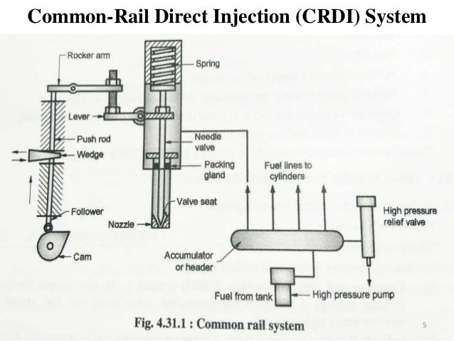
Common Rail Direct Injection or CRDI System: working, advanatages
Printable Schematics/Wiring Diagrams. FAST® XFI™ 4 CYLINDER INJECTOR HARNESS PART #301207. FAST® XFI™ 8 CYLINDER INJECTOR HARNESSES -PART #301200-206. FAST® XFI™ 4 STAGE NITROUS WIRING HARNESS - PART#301400. FAST® CLASSIC TO XFI™ ADAPTER HARNESS. FAST® CLASSIC EFI SYSTEM MAIN HARNESS - PART#307012. FAST® CAN NETWORK.
How a fuel injection system works | How a Car Works
Fuel injection has had a profound impact on how the modern combustion engine works. Find out how here.

Powerplants – Fuel Injection Systems
If you’re wondering where to buy kerosene fuel, you’re probably heading out on a camping trip, using kerosene as an alternative to natural gas in your heater or setting up your emergency lamps for bad weather. Kerosene fuel is versatile and...

Air Injection System - Diagram , Working , Advantages
Direct injection of fuel into cylinders offers better fuel distribution and easy cold starting, without the threat of carburetor icing. Jacqueline Shipe (A&P/IA) walks you through a typical Lycoming fuel injection system and the most common trouble spots to check if your engine starts running rough.
How a fuel injection system works | How a Car Works
We do back-to-back testing on a carburetor and fuel injection to see which one performs best on a 6.0L LS engine.
Introduction to Fuel Injection | Common Service Manual
3 Fuel System (With MCM Heat Exchanger) –Two-Filter System 1. Fuel Tank 2. Fuel Supply from Tank 3. Pre-filter 4. Hand Primer 5. Low Pressure Fuel Pump 6. Fuel Bypass Valve 7. Water Coalescer / Final Filter 8. High Pressure Fuel Pump 9. Fuel Rail 10. High Pressure Fuel Injector Lines 11. Fuel Injectors 12. Needle Return Line 13. Needle Return Pressure Control Valve 14.

An Introduction Fuel Systems in Internal Combustion Engines ...
Edelbrock has been delivering the best combination of dyno proven electronic fuel injection performance for over 40 years. Pro-Flo 4 is not just a replacement for your carburetor, it's a complete engineered system that provides the ultimate in performance, drivability and quality.

Automotive Fuel System Infographic Diagram Showing Parts Of ...
FAST is the leading developer of electronic fuel injection systems, EFI components, intake manifolds, tuning tools for high performance and street applications

What is Direct Injection Technology And How It Works ...
The steel ball and the piston of the fuel overflow valve when it is activated Figure 7 illustrates the main parts of the injection system and explains the flow ...

File:Marvel Fuel Injection System Cross Section.png ...
Air injection system: It was first developed by Rudolf Diesel. The arrangement of the system is shown in fig In this system, air and fuel both are injected into the cylinder during the supply of fuel. The required pressure of the air for injecting the fuel is about 70 bar or higher. A fuel pump is driven by the engine itself.

Multi-point Mechanical Injection System (Automobile)
The following diagram provides an overview of how the fuel injection components are integrated. 4.0 OPERATING CONDITIONS There are six major operating conditions that the components of the L-Jetronics fuel injection system must detect and provide inputs to the control unit in order to provide the correct fuel-air mixture.
Electronic Fuel Injection - ppt video online download
We all have fuel tanks in our cars, but most of us don’t really pay attention to them, unless they’re empty that is. Fuel tanks come in a variety of sizes, with compact cars generally having much smaller capacity tanks than large cars or tr...

Electronic Fuel Injection System (EFI) - Architecture, Types ...
14. nov. 2018 ... Petrol Fuel Injection System Diagram ... The injection system in the petrol engine consists of several parts including; ... The fuel pump does not ...

A schematic diagram of the fuel injection system | Download ...
Find EFI systems from Edelbrock, FAST, Holley, MSD Ignition, ACCEL, and more at Summit Racing and get fast shipping and great service!
Basics of engine management
The term "fuel injection" is vague and comprises various distinct systems with fundamentally different functional principles. Typically, the only thing in common all fuel injection systems have is the lack of carburetion. There are two main functional principles of mixture formation systems ...
Fuel Injection Systems
tion system is particularly useful when combined with a combustion model. However, modeling an injection system is di cult. Conventionally, the injection system of a diesel engine comprises a pump, a high-pressure pipe, and an injection valve. Because the fuel is compressible, pressure waves are formed in the system. The ow at a given point of the
Fuel Injection Common Rail Injector Diesel Engine, PNG ...
Once the injector pump or timing valve cuts off the high pressure fuel supply the needle valve will shut quickly under the spring compression force. All slow-speed two-stroke engines and many medium-speed four-stroke engines are now operated almost continuously on heavy fuel. A fuel circulating system ...

Gasoline Injection (Automobile)
Components of the fuel system. Understanding the basic layout of a fuel system, additional components make the mechanical fuel injection system useful. A barrel valve or metering valve controls the appropriate amount of fuel for starting, part-throttle, driving, and stopping. A barrel valve is also used to throttle the fuel for part-throttle ...
Comments
Post a Comment