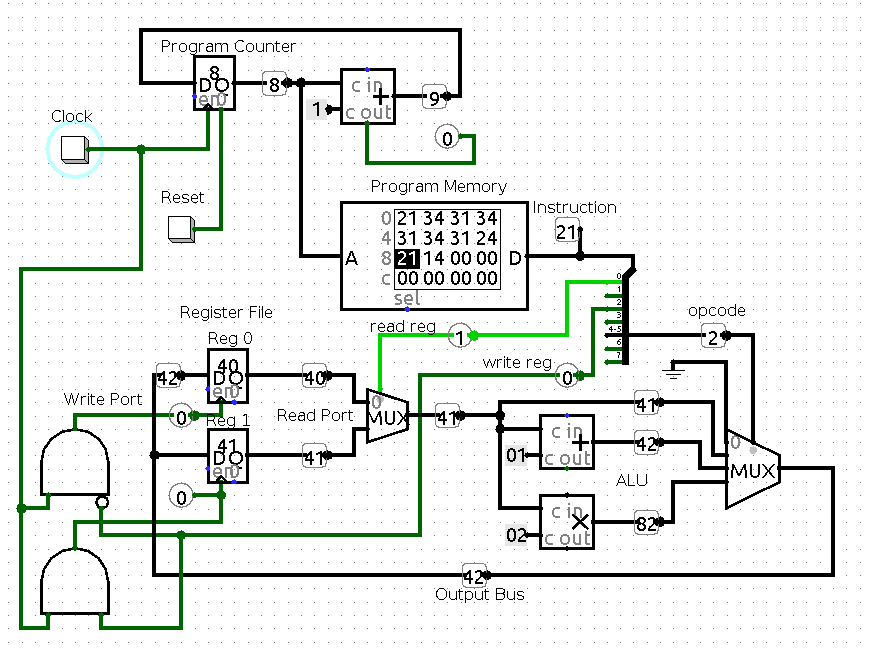
42 cpu circuit diagram
The tiny part of circuit in the OP seems pretty meaningless, it's not a 'simplified' processor, but merely a tiny part of one. For the OP - I would completely ignore the 'diagram', it's of no use to you (or anyone else), and presumably was only given to explain a small specific point. November 19, 2015 - Cookies are disabled for this browser. Wiley Online Library requires cookies for authentication and use of other site features; therefore, cookies must be enabled to browse the site. Detailed information on how Wiley uses cookies can be found in our Privacy Policy · Your password has been changed
Quantum circuit diagram conventions In a circuit diagram, each solid line depicts a qubit, or more generally, a qubit register. By convention, the top line is qubit register 0 0 and the remainder are labeled sequentially. Operations are represented by quantum gates. The term quantum gate is analogous to classical logic gates.
Cpu circuit diagram
determined. Figure 3 is an example of an electronic schematic diagram. Figure 3 Example of an Electronic Schematic Diagram A second type of electronic schematic diagram, the pictorial layout diagram, is actually not so much an electronic schematic as a pictorial of how the electronic circuit actually looks. 1.1 Basic information about how the CPU works Getting started with S7-1200 Getting Started, 11/2009, A5E02486791-01 9 1.1.2 Operating modes of the CPU The CPU has three modes of operation: STOP mode, STARTUP mode, and RUN mode. Status LEDs on the front of the CPU indicate the current mode of operation. Download FREE diagrams, schematics, service manuals, operating manuals and other useful information for a variety of products. Currently we have 27502 Diagrams, Schematics, Datasheets and Service Manuals from 978 manufacturers, totalling 16.22 GB and the range is expanding all the time.
Cpu circuit diagram. Input / output wiring of different types of CPU Figure 1. Cpusr20 wiring diagram Figure 2. Cpusr40 wiring diagram Figure 3. Cpucr40 wiring diagram Figure 4. Cpust40 wiring diagram Figure 5. Cpusr60 wiring diagram Figure 6. Cpust60 wiring diagram Digital input wiring Figure 7. Drain input connection figure 8. Source input connection Photo by Siu Man Chan · View the undergraduate and graduate course schedule for current and past semesters Components were identified by desoldering and measuring everything on a AGS-CPU-11 board. Note: there are several versions of Advance SP mainboards, and these schematics have accurate information only for AGS-CPU-11. Game Boy Advance SP AGS-001 mainboard (AGS-CPU-11) schematics. Raw notes of AGS-CPU-11 board components. Traced AGS-CPU-11 board SVG Download scientific diagram | Circuit diagram of the CPU structure. from publication: A microcontroller-based system for automated and continuous sky glow measurements with the use of digital single-lens reflex cameras | In recent years, the scientific community has shown an increased interest ...
common, or grounded, Base circuit, whereas FE means Forward current transfer ratio of the common, or grounded, Emitter circuit. Basic configuration of Common-Base . First circuit •If V EE = 20V and V EB is negligible, find I E when R E equals (a) 80kΩ, (b) 40kΩ, (c) 20kΩ, (d) 10kΩ, (e) 5kΩ, and (f) Major parts of a CPU []. Below we see a simplified diagram describing the overall architecture of a CPU. You must be able to outline the architecture of the central processing unit (CPU) and the functions of the arithmetic logic unit (ALU) and the control unit (CU) and the registers within the CPU.. Do I understand this, part one [] Z80 Schematic This is a system example with PARALLEL, SERIAL, RAM and ROM. Z80 Schematic (Protel) The schematic above in the original Protel format. 3 GIFs with Z80 Circuits Z80 CPU and Memory, CTC, SIO, and drivers for RS-232 interface. Z80 system circuit Z80 CPU with EPROM, RAM and PIO, by M.Kimura. Nov 1, 2019 - 16-bit CPU in Logisim, Microprocessor design in Logisim, ... multiplexer logisim Dc Circuit, Block Diagram, 16 Bit, Control Unit, ...
2. jul. 2017 ... Alternatively, it is also known by the name of processor, microprocessor or a computer processor. A CPU is an electronics circuit used in a ... Characteristic : Speed, Accuracy, Reliability, Storage, Automation, Verstality, Diligence. Computer are the electronic devices which takes input from the user, processes the data and gives the exact output to the user. A central processing unit (CPU), also called a central processor, main processor or just processor, is the electronic circuitry that executes instructions comprising a computer program.The CPU performs basic arithmetic, logic, controlling, and input/output (I/O) operations specified by the instructions in the program. This contrasts with external components such as main memory and I/O ... Circuit Diagram Of Smps Power Supply Fly-Back Converter. The unregulated input-voltage with a constant value is converted into a required output voltage by fast switching with the help of a 'MOSFET'; the switching frequency is around 100 kHz. The isolation of voltage can be achieved by means of a transformer.
Simple CPU Design
* Your assessment is very important for improving the workof artificial intelligence, which forms the content of this project
CPU processor with graph and diagram on the circuit board ...
Dec 23, 2017 · Computer Cpu Circuit Diagram. Circuit diagram of the cpu structure scientific nodes schematic implementation simple design v1 online cs modules central processing unit defpom cb and ham page build an 8 bit computer ben eater a typical motherboard power supply under circuits 58890 next gr mdfs info comp bbc control custom 4 big mess o wires off ...

Fan Tachometer Schematic / Circuit Diagram
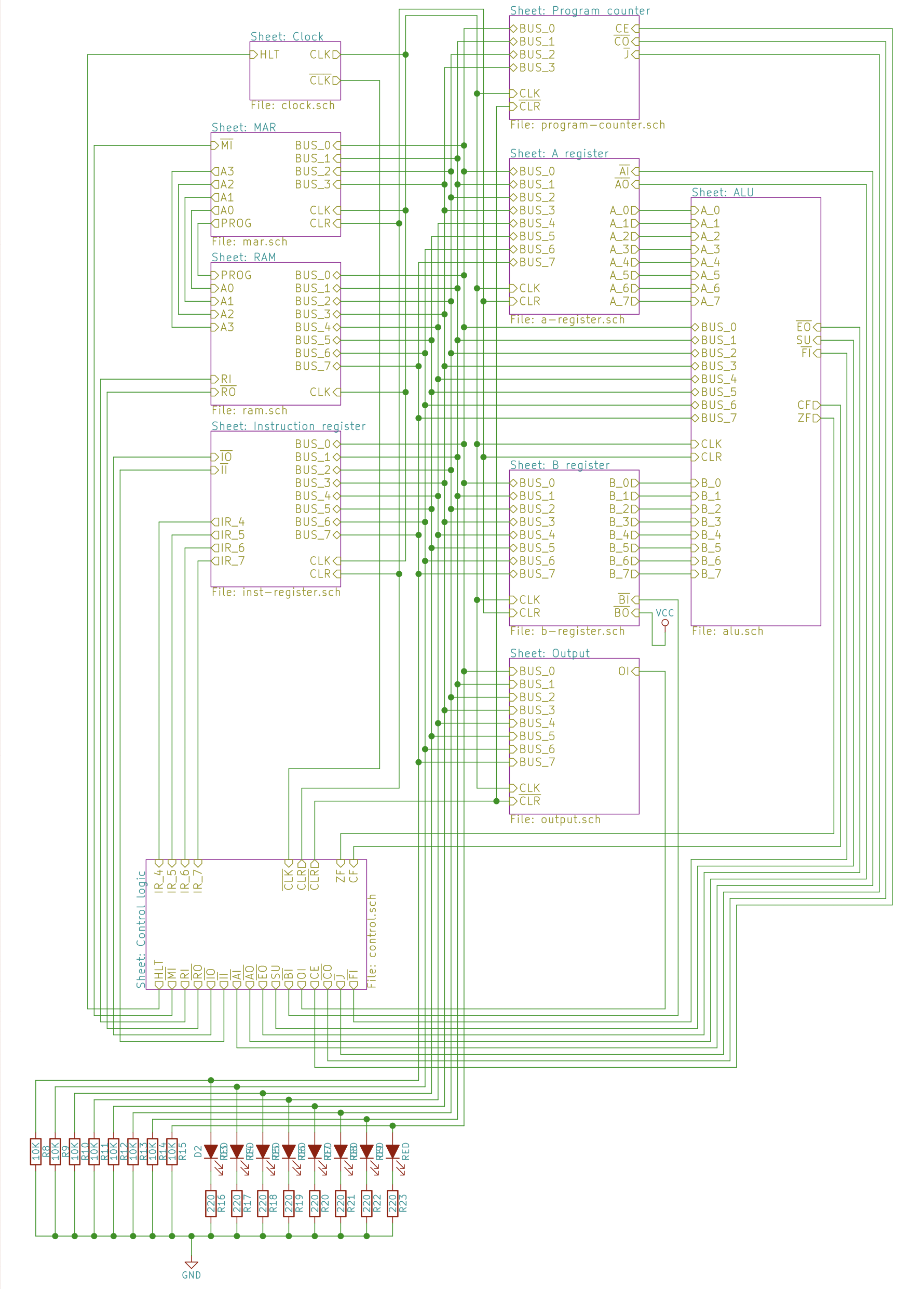
Schematics. I'm starting to make some progress with Eagle (light) and I'll be adding schematic diagrams of all of the circuits that make up my CPU. I just finished doing the 3rd Eagle layout of the program counter and this one actually makes sense to look at. The first two were a mess of wires intersecting and crossing over each other so that ...

Cpu Circuit Diagram and Yen, 3d Stock Illustration ...
PLC Siemens CPU 221/222 is an extremely popular PLC in the industry! Its durability is very high but not never broken! It may be broken due to environmental conditions or physical effects as well as wrong connection! So today I share to everyone the circuit diagram of CPU 221/222. Hope it helps people when needed […]
Build an 8-bit computer | Ben Eater
A circuit diagram is a visual display of an electrical circuit using either basic images of parts or industry standard symbols. Symbol usage depends on the audience viewing the diagram. These two different types of circuit diagrams are called pictorial (using basic images) or schematic style (using industry standard symbols).
An Example Hardwired CPU
Most CPUs operate on values of more than one bit. Using a single bus to represent multiple bits with a single line dramatically simplifies the circuit schematic compared to the physically more realistic approach of drawing separate wires for each bit. Logisim calls this "Data Bits"; most other ...
Computer: CPU (Central Processing Unit) - Tutorial And Example
October 8, 2021 - Read Or Download Diagram Of For FREE A Cpu at DIAGRAMHS.CXLECCE2021.IT

Schematic diagram of the CPU implementation | Download ...
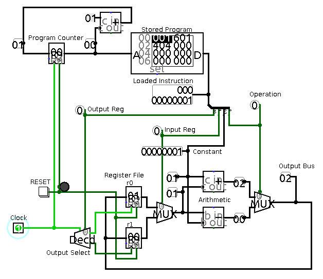
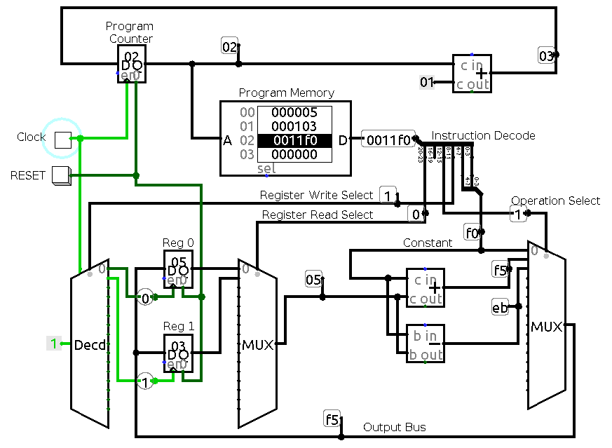
I am trying to gain a high level insight into how the diagram in the link maps to a circuit diagram like this: For example, have a look at the assembly language statement: ADD 1,2. I am trying to understand how the processor produces '3' as the output. I realise that this question may be difficult to answer in simple terms.

XYT-CPU: A 8 bit CPU built from scratch in Logisim | Meng ...
Recently I was asked for a diagram of a typical water cooling loop that would include a cpu and gpu. So, I made a post describing the best possible flow to include a processor and video card. This is only for a single video card, and not intended for an SLI or Crossfire setup. The starting point for a loop always starts with your reservoir.

16-bit CPU in Logisim, Microprocessor design in Logisim ...
Fortunately, I found that by reusing blocks from the CPU schematics, I could reproduce a correct schematic diagram in a relatively short time. The situation with the ROM was not as straightforward. To get me started, Tim sent me two high resolution photomicrographs of the Intel 4001 ROM, one of the unmodified chip, and one of the chip with the ...
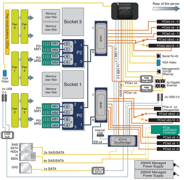
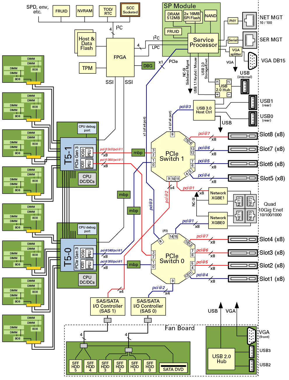
1.1 System Overview - Sun Fire X4470 Server
The central processing unit (CPU) The CPU in modern computers is the embodiment of the "mill" in Babbage's difference engine. The term central processing unit originated way back in the mists of computer time when a single massive cabinet contained the circuitry required to interpret machine level program instructions and perform operations on ...

Master Electronics Repair !: H BUSTER HBD 9250 DVD SCHEMATIC ...
6502 svg schematic. This is an svg schematic of a 6502 microprocessor, consisting of a block diagram and a circuit diagram . The latter follows the circuit of the original MOS Technology 6502 (as reverse engineered at visual6502.org) very closely, and the layout of the chip quite closely: differences with the original are noted in the file diff ...

The CPU circuit diagram of the nodes. | Download Scientific ...
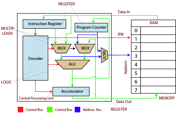
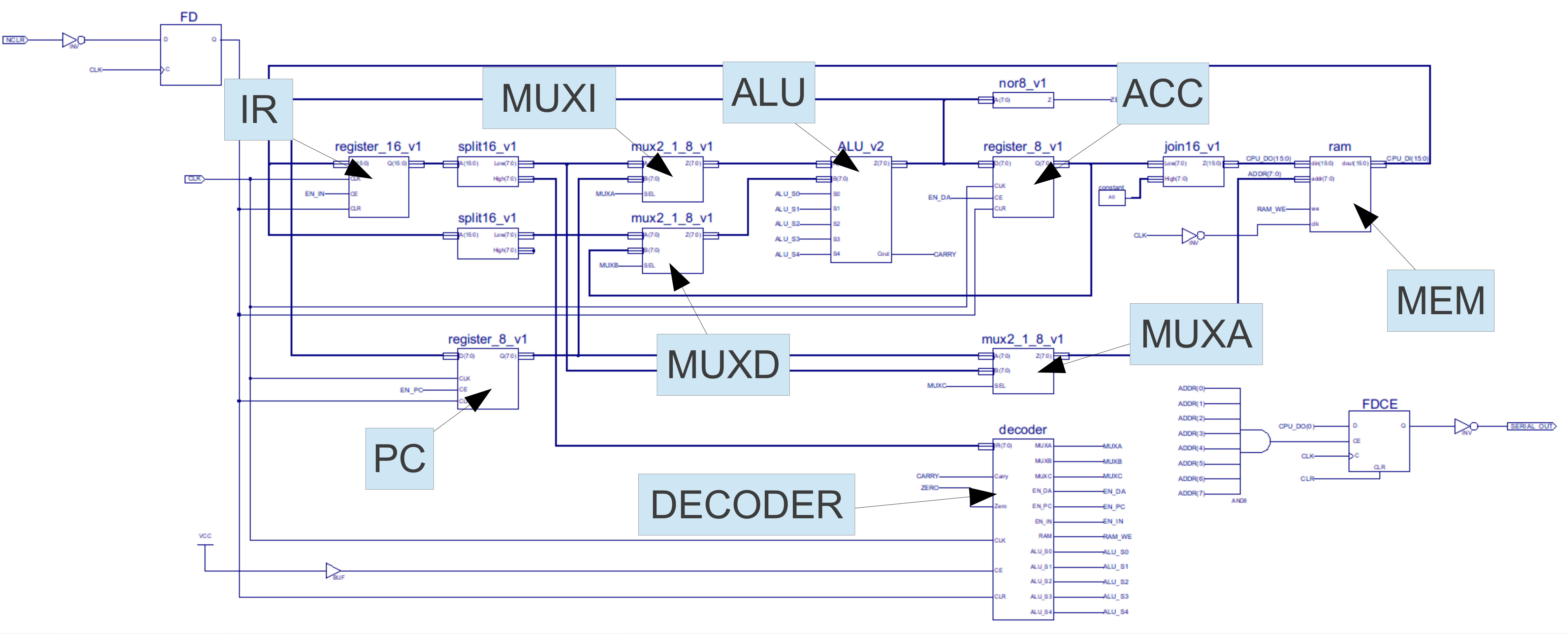
These are contained within the decoder or control-logic block (figure 1), the circuit diagram symbol for this component is shown in figure 24. Inside this component are the instruction decoding logic and sequence generators needed to control the processor, as shown in figure 25. A high resolution diagram can be downloaded here: .

Circuit Board Cpu Vector Illustration Stock Vector (Royalty ...
December 27, 2018 - Aug 8, 2016 - Absolutely Free Web Hosting with PHP, MySQL, cPanel and no Ads!

Processor Fan Controller Circuit
Learn how the CPU processes data, see how to identify a CPU on a simple computer, and reflect on the layers of hardware and abstraction inside the CPU.
Schematics for a computer processor : r/interestingasfuck
This is a conceptual circuit diagram of the power train of a typical ATX computer power supply unit. This schematic does not show the control circuitry, that's why you see all MOSFET gates and transistor bases are open. For clarity, the parts responsible for miscellaneous auxiliary functions, such as current limit, fan control, and OV ...
My CPU short-circuited. How do I fix it? - Quora
December 4, 2020 - How is the circuit designed to have the intelligence of calculation and control? This is not profound at all. From the beginning of the article, a simple circuit diagram can not be learned from the CPU. The circuit diagram is drawn with Multisim 12.0, so you can see the effect. (Note: Although ...
ADP3160_Typical Application Reference Design | DC to DC ...
The name CPU 31x summarizes all standard CPUs, as table below shows: CPU Convention: CPU designations: Order number As of firmware version CPU 312 6ES7312-1AE14-0AB0 V3.3 CPU 314 6ES7314-1AG14-0AB0 V3.3 CPU 315-2 DP 6ES7315-2AH14-0AB0 V3.3 CPU 315-2 PN/DP 6ES7315-2EH14-0AB0 V3.2 CPU 317-2 DP 6ES7317-2AK14-0AB0 V3.3 ...

CPU Cooler With Electronic Diagram Isolated Stock Photo ...
Defective U1 (CPU) Defective U2 (PPU1) Defective U4 or U5 (256K S-RAM) Distorted or no sound Defective Sound Module Defective connector P5 Defective U1 (CPU) Defective U10 (Amp) Defective Q18 No Reset (This is system /RESET, not the reset button, although the button ties in to the circuit too) Defective US (CIC) Defective X2 (4MHz oscillator)
Simple CPU Design
Diagrams of the Original Schematics for the 4004. The following are photographs of Federico's original schematics for the 4004, in 3 sheets, with hand notations in pencil by Federico: The Memory Block containing the index registers dynamic memory, address stack dynamic memory, program counter with incrementer, refresh counters, and effective ...
Schematic circuit diagram of CPU and control unit. | Download ...
Block diagram Working: CPU consists of three basic units: control unit, Arithmetic Logical Unit (ALU) and memory unit. Input is given through the input devices to CPU. Control unit controls communication within ALU and memory unit. Decides which circuit is to be activated. For reading instruction it uses Fetch-execute mechanism.

Computer Block Diagram and Architecture Explained - ETechnoG
May 20, 2021 - In the above block diagram of CPU, you can see there are mainly three blocks of the CPU - 1. Control Unit or CU 2. Arithmetic & Logic Unit or ALU 3. Memory Unit · Let's discuss the function of each block of the CPU. ... The main function of the Control Unit of a CPU is to control all components of the ALU Circuit...

Schematic diagram of the CPU implementation | Download ...
I create tutorial-style videos about electronics, computer architecture, networking, and various other technical subjects.
Simple CPU Design
Figure 6 : CPU block diagram. Again, thick lines in the circuit diagram indicate busses i.e. a collection of wires, either 16 bit or 8 bit wide. Thin lines control signals i.e. single wires, bits. This is the main difference between a block diagram and a circuit diagram, you start to get a little bit more clutter with all the wires required to ...

ELECTRONIC CIRCUIT DIAGRAM | ELECTRO SCHEMATIC: VOLTAGE ...
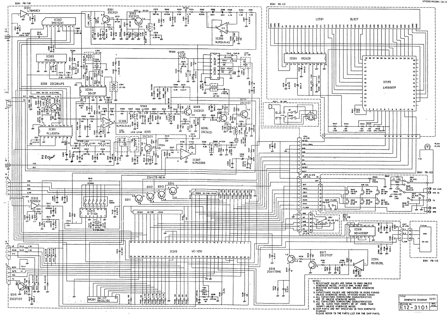
October 2, 2019 - This will be a quite long log.... luckily, it will naturally stop when all 42 IC's have been explained... This will be a detailed description of the schematic. For a good understanding, first read the first log and the logs that follow it. The schematic was split into nine sections, that ...

Circuit diagram of the CPU structure. | Download Scientific ...
Q Factor for Quartz crystal: Q is the short form of Quality. It is an important aspect of quartz crystal resonance. This Q factor determines Crystal’s frequency stability. In general, the Q factor of a crystal has a range from 20, 000 to more than 100,000. Sometimes, the Q factor of a crystal is more than 200,000 also observable.
4-Bit Mini CPU - CircuitLab
CPU Board. This schematic includes: LR35902, The main CPU (Commonly known as GB-Z80; with pinout) LH5264, 8192 byte work RAM (With pinout) LH5264, 8192 byte video RAM (With pinout) External Link Port (With pinout) Game Cartridge Socket (With pinout) Joypad Matrix (D-pad: Left, right, up, down. Buttons: B, A, Start, Select) Audio Amplifier
Rogerbirds Radio Modification Information Page
CPU 1215C wiring diagrams. Siemens PLC bigplc • December 25, 2021 • Comments off. CPU 1215C AC/DC/Relay (6ES7215-1BG40-0XB0) wiring diagrams. Note 1: X11 connectors must be gold. Note 2: Either the L1 or N (L2) terminal can be connected to a voltage source up to 240 V AC. The N terminal can be considered L2 and is not required to be grounded.

Electronic Circuit Diagram With CPU Cooler Isolated Stock ...
The design process for the CPU in Logisim: 1. Multiplexers: Figure 2. The screenshot of multiplexers. In this design, multiplexers module will get the 10-bit select signal from control unit and output the one of 10 16-bit data input. To design this module, we can see that the multiplexer will transfer the Nth 16-bit data input to the output if ...
SFL Examples
Computer Science and Engineering: Simple Block Diagram of CPU ... Laptop Notebook Motherboard Circuit Diagram | Car Wiring Diagram. More information.

Cpu circuit diagram creative image_picture free download ...
Download scientific diagram | Schematic diagram of the CPU implementation from publication: Designing a RISC CPU in reversible logic | Driven by its promising applications, reversible logic received significant attention. As a result, an impressive progress has been made in the development ...
System Schematic - SPARC T5-2 Server Service Manual
Download FREE diagrams, schematics, service manuals, operating manuals and other useful information for a variety of products. Currently we have 27502 Diagrams, Schematics, Datasheets and Service Manuals from 978 manufacturers, totalling 16.22 GB and the range is expanding all the time.
![PDF]- PLC Siemens CPU 221/222](https://plc4me.com/wp-content/uploads/2019/09/Untitled-7-810x467.png)
PDF]- PLC Siemens CPU 221/222 "Schematic diagram" - plc4me.com
1.1 Basic information about how the CPU works Getting started with S7-1200 Getting Started, 11/2009, A5E02486791-01 9 1.1.2 Operating modes of the CPU The CPU has three modes of operation: STOP mode, STARTUP mode, and RUN mode. Status LEDs on the front of the CPU indicate the current mode of operation.

CPU and circuit lines stock illustration. Illustration of ...
determined. Figure 3 is an example of an electronic schematic diagram. Figure 3 Example of an Electronic Schematic Diagram A second type of electronic schematic diagram, the pictorial layout diagram, is actually not so much an electronic schematic as a pictorial of how the electronic circuit actually looks.

Schematic | 4-Bit CPU

Circuit design for co-layout the XTAL and CPU clock output ...
CPU Processor Circuit Diagram Sticker by Blaacklight
Simple CPU v1

The CPU circuit diagram of the nodes. | Download Scientific ...
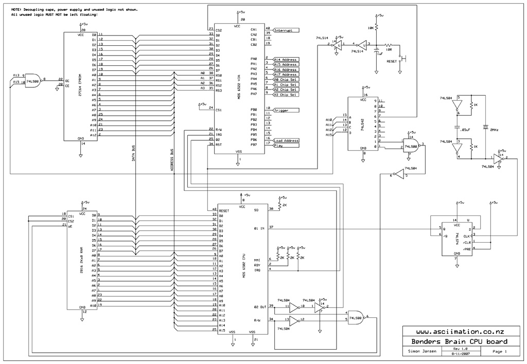
The Bender Brewer Project

XYT-CPU: A 8 bit CPU built from scratch in Logisim | Meng ...

Reading: The Central Processing Unit | Introduction to ...
Comments
Post a Comment