42 class responsibility collaboration diagram
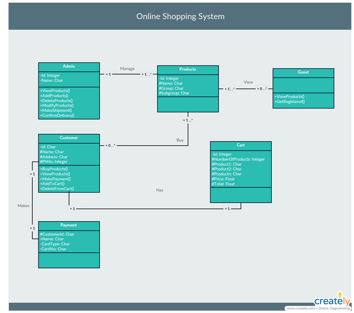
The collaboration diagram is used to show the relationship between the objects in a system. Both the sequence and the collaboration diagrams represent the same information but differently. Instead of showing the flow of messages, it depicts the architecture of the object residing in the system as it is based on object-oriented programming. Below are some criteria of which a Structural Model in the form of a set of Class-Responsibility-Collaboration (CRC) cards and a class diagram will need to Question : Background: 1-On this case study, you will continue to be working as a systems analyst to build an aspect of an Electronic Health Record (EHR) system, the Computerized Physician ...
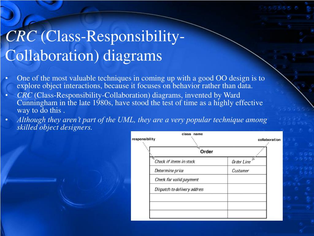
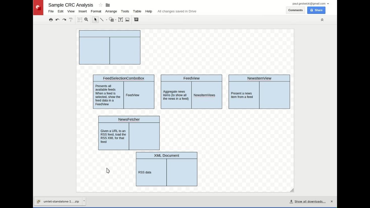
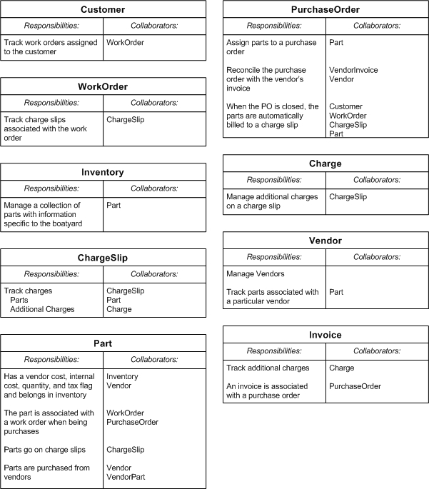
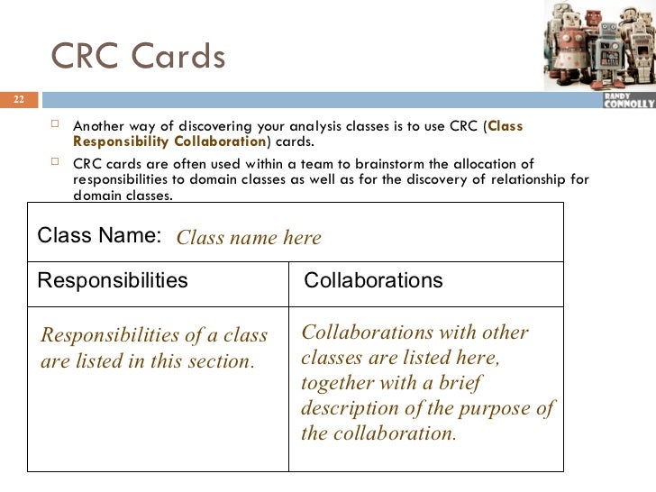
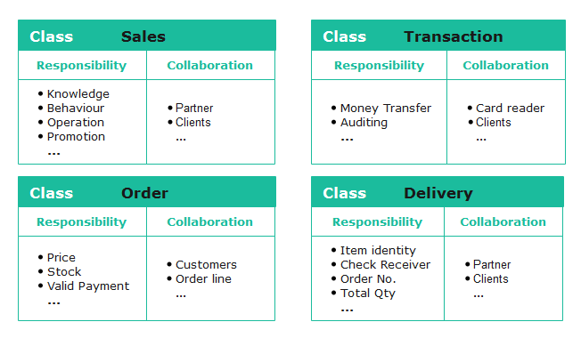
Client Server (or helper) * CS 4311 Collaboration Graph Graphical representation of collaborations Arrow from client to a “contract” of the server, denoted by a semicircle Contract: group of responsibilities (more on this later) Person AddressBook 1 PhoneBook 2 * CS 4311 Example: Mail-Order System Class Responsibilities Collaborators ...

Class responsibility collaboration diagram
A Sequence diagram is an interaction diagram that details about the operation that is carried out. The sequence diagram captures the interaction between the objects in the context of collaboration. Sequence diagrams are time focused and they show the order of the interaction visually by using the vertical axis of the diagram to represent time. Usage. The collaboration diagram is also called a communication diagram or interaction diagram. It consists of an object, multi-object, actor, association role, delegation, link to self, constraint, and note. Objects are model elements that represent instances of a class or classes. A multi-object represents a set of lifeline instances. Collaboration diagrams (known as Communication Diagram in UML 2.x) are used to show how objects interact to perform the behavior of a particular use case, or a part of a use case.Along with sequence diagrams, collaboration are used by designers to define and clarify the roles of the objects that perform a particular flow of events of a use case.
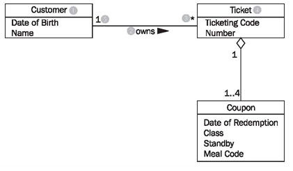
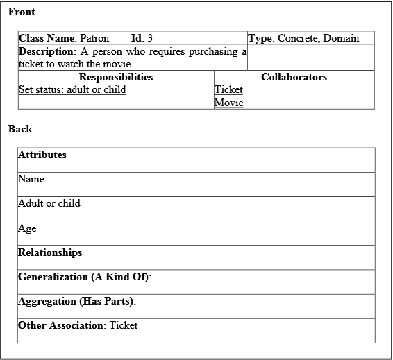
Class responsibility collaboration diagram. #uml #sad #crc #cards #class #reponsibility #collaboration #cards #karanjetlilive Interaction diagrams is the superset of Sequence diagrams and Collaboration diagrams An interaction diagram captures the behaviour of a single or more use cases Within Sequence Diagram, each vertical line is called the object's lifeline; each message is represented by an arrow between the lifelines. Consider that all messages presented on the Collaboration diagram become responsibilities of the receiver object class (i.e. they become methods of that class). Also, consider that each instance of Room in the Hotel Rooms class has a unique identifier Room No, and attributes like No of beds, and Room rate. Class responsibilities can be confused. ... Sequence Diagram And Collaboration Diagram. Figure 3. q Parameterized Class (Figure 4) Generic programming or C++ templates (e.g. STL). Code reuse among semantically similar families of classes. Associative arrays, maps, dictionaries, etc.
Collaboration diagrams (known as Communication Diagram in UML 2.x) are used to show how objects interact to perform the behavior of a particular use case, or a part of a use case.Along with sequence diagrams, collaboration are used by designers to define and clarify the roles of the objects that perform a particular flow of events of a use case. Usage. The collaboration diagram is also called a communication diagram or interaction diagram. It consists of an object, multi-object, actor, association role, delegation, link to self, constraint, and note. Objects are model elements that represent instances of a class or classes. A multi-object represents a set of lifeline instances. A Sequence diagram is an interaction diagram that details about the operation that is carried out. The sequence diagram captures the interaction between the objects in the context of collaboration. Sequence diagrams are time focused and they show the order of the interaction visually by using the vertical axis of the diagram to represent time.
PPT - Object-Oriented Design PowerPoint Presentation, free ...
Class Diagram

Class Diagram Slide ppt download
Class-responsibility-collaboration card | Semantic Scholar

Class Responsibility Collaborator (CRC) | Graffletopia

CRC-cards for the Library Example | Download Scientific Diagram

What Is the Extreme Programming Methodology? | Lucidchart Blog
PPT - Object Oriented Analysis and Design PowerPoint ...
PPT - Chapter 3 Class Diagrams: The Essentials PowerPoint ...

CSC/ECE 517 Fall 2012/ch1 w43 - PG_Wiki
CRC Card Analysis Example
Chapter 5 Solutions | Systems Analysis And Design With Uml ...

IS514 Lecture Week 9 CRC Cards. - ppt download
Chapter 6, Designing with Objects

Lecture 4 Class Responsibility Collaboration Cards - ppt download

Class Responsibility Collaborator for Top Level Agent ...

A class diagram of collaboration processes. | Download ...

Class Responsibility Collaborator (CRC) Models: An Agile ...
Advanced Unit Testing-UML软件工程组织-ç«é¾™æžœè½¯ä»
Validation: CRC Cards
OO Development 5 - Analysis
A Laboratory For Teaching Object-Oriented Thinking
Validation: CRC Cards

George Blank University Lecturer CS 602 Java and

PDF) A pattern for an effective class responsibility ...

How to make crc (class responsibility collaborations) cards? explained with example
Applying the concept of Class Responsibility Cards to ...

How to use CRC cards for OO design | Shabbir Mirza

Flowchart of class responsibility collaboration model ...
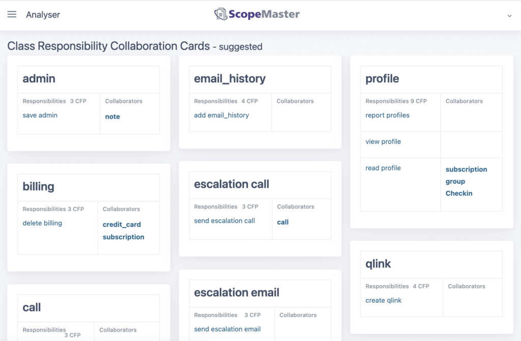
Class Responsibility Collaborator Cards - ScopeMaster

Home Appliance Control System - PDF Free Download

A Laboratory For Teaching Object-Oriented Thinking
CRC Card Software for Windows, Mac and Linux - Edraw

Notations - Pattern-Oriented Software Architecture, Volume 1 ...
How to Draw Class Diagrams: Simple Class Diagram Rules for ...
OO Software Engr.: Modeling with UML

Class Responsibility Collaboration
Solved Do the CRC cards ( Class Diagram (UML)) for | Chegg.com
The Ultimate Class Diagram Tutorial to Help Model Your ...

CRC-cards for the Library Example | Download Scientific Diagram

PPL C bimo: October 2016
UML - Basic Notations
Comments
Post a Comment