41 rainbird wiring diagram
rainbird sprinkler wiring diagram - Architectural electrical wiring diagrams show the approximate areas and also affiliations of receptacles, lighting, and permanent electrical services in a structure. Adjoining cord courses might be shown about, where certain receptacles or fixtures must get on an usual circuit. LXME System Wiring Diagram. 4 ESP-LXME Controller ESP-LXME Model Variants Rain Bird offers different variants of the ESP-LXME controller, depending on your irrigation requirements. Available options include: Model Modules Included ESP8LXME BM-LXME Base Module ESP-LXM-SM8 Station Module
DIAGRAM.Rain Bird Commercial Valves (PGA, PEB, PESB, PESB-R, EFB-CP, GB, BPE, BPES) - Spare Parts. The official online store for Rain Bird Corporation Golf Division selling the complete line of genuine Rain Bird golf rotors, swing joints, valves, accessories and replacement parts. Aug 05, · Helpful overview of the basic operation for Rain Bird ...

Rainbird wiring diagram
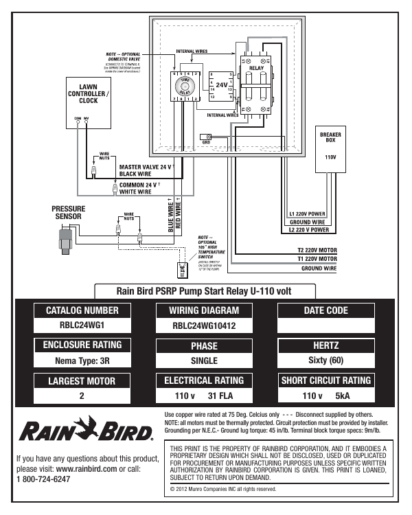
The following diagrams show wiring details for pump start relay and pump motor starter wiring for various Rain Bird controllers. Figure 1: This is a basic pump start wiring diagram for most controllers. This diagram assumes the Master Valve circuit is being utilized for the pump start circuit. Rainbird Valve Diagram. sprinkler or elevated piping in the circuit to meet most codes, (See Diagram. 1. ( Consult local building code.) CAUTION: Do not use this anti-siphon valve as a. Rain Bird valves provide . Rain Bird residential valves cannot be used with PRS pressure regulating modules controller out to the first valve on a circuit and. rain bird ssti wiring diagram for orbit pump start relay besides sensor also sstin review. rain bird ssti watering timers. call Rain Bird toll-free Technical Support at: RAIN BIRD () or visit diagramweb.net Connect an optional Rain Sensor to the Timer Remove the wiring bay cover at the bottom of the unit.
Rainbird wiring diagram. Sprinkler timer sprinkler wire header line 1 p lateral sprinkler line 3 4 valve manifold s 07wtm003045 53251 01 re qxd 3 2 07 2 30 pm page 3. Assortment of rainbird sprinkler wiring diagram. A wiring diagram is a streamlined standard pictorial representation of an electrical circuit. Collection of sprinkler system wiring diagram. 5 ESP-ME3 Controller EN Connect Pump Start Relay (optional) a Connect a wire from the PSR (pump start relay) to the MV (master valve) terminal on the Base Module.Then connect another wire from the pump start relay to the field common wire, as shown. b To avoid the possibility of damage to the pump, connect a short jumper wire from any unused 25.04.2019 25.04.2019 1 Comments on Rain Bird Esp-rzx Wiring Diagram The popular Rain Bird ESP Series of controllers has been expanded to The ESP-RZX Controller provides zone based set up that is easier to A guide for ½ or ¾ conduit allows for professional installation of field wires into the cabinet. You most likely know already that rainbird esp me wiring diagram is among the top topics on the web at this time. Based on the details we got from google adwords, rainbird esp me wiring diagram has a lot of search online web engine. We think that rainbird esp me wiring diagram present fresh options or references for audience.
The following wiring diagram from a leading manufacturer of decoder systems shows the complexity of the wiring inside a valve box of a decoder installation. The average landscape maintenance contractor is not qualified to troubleshoot these kinds of systems. Rain Bird GT27141C manual, dated November 2003, page 50 of 153. Rainbird Wiring Diagram Remotely manage irrigation systems from your computer or smartphone with Rain Bird's IQ Platform. Save time and water by managing multiple sites and. Automated Rain Bird irrigation systems are composed of three essential parts: Wiring the solenoid correctly ensures the correct valve is activated when turned. DIAGRAM 1 The Rain Bird Ec controller is an electronic timer that controls when your sprinkler system turns on, and how long the sprinklers run. Depending on the model, the Ec can control four, six, or nine watering fistations.fl A€station is a series of sprinklers, or other irrigation devices, connected to a common remote control valve. power sources to irrigation controllers (choose one of the following): SINGLE CONDUCTORS, TYPE UF - This type of wire is a general purpose, direct burial, product that is widely used on all kinds of irrigation systems. Available from 14 AWG up to 1/0 AWG. See specification number P7001D for available colors and stripes. Detailed color
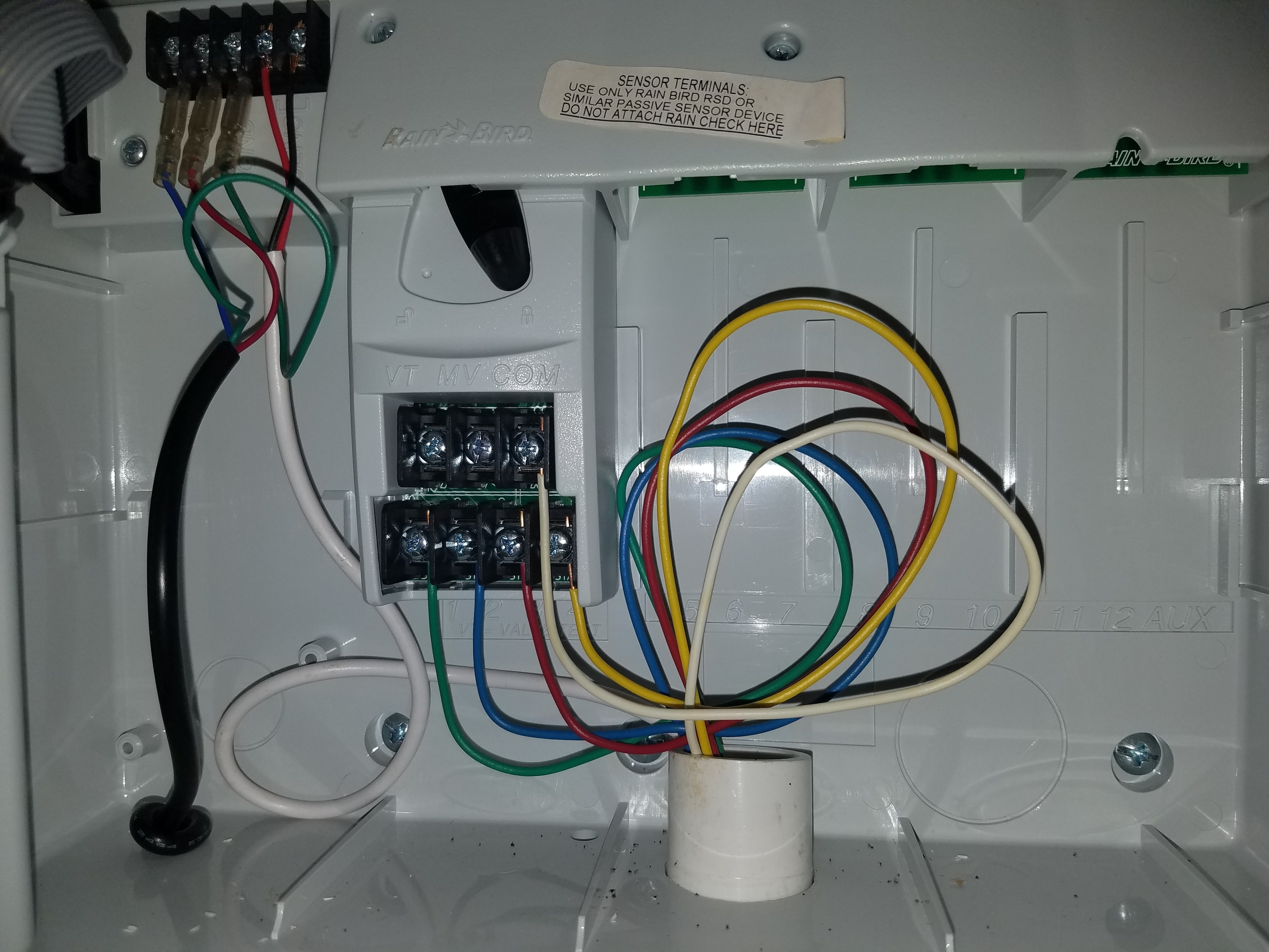
Wiring sensors is quite simple. The following wiring diagrams will assist you in wiring most common types of sensors. Figure 14: This diagram shows how to wire a rain sensor device. (Rain Check) *This splice should be between the controller and the valves, pump start relay or mas-ter valve. * Rain Bird Esp-me Wiring Diagram. View and Download Rain Bird ESP-Me advanced user's manual online. Controller Rain Bird ESP Installation, Programming & Operation Manual . Wiring Connections Connect Master Valve Connect the valve wires for each station and for. Program based scheduling allows 4 individual programs with independent start times ... irrigation controllers at the Rain Bird Online Store.* Enter discount code: UPGRADE15 at checkout to save an extra 15% o˜* * Additional discount not valid on clearance items, bundles or store specials. Discount applies to controller products only. Cannot be combined with other store discount codes. Valid at the Rain Bird Online Store only. Rain Bird offers many types of sprinkler systems, and they don't all come with color-coded wires. In those that do, the wire colors reflect the station number the wire controls. In general, the ...
How to install & program a Rain Bird ESP Series timer - YouTube
irrigation controllers at the Rain Bird Online Store.* Enter discount code: UPGRADE15 at checkout to save an extra 15% o˜* * Additional discount not valid on clearance items, bundles or store specials. Discount applies to controller products only. Cannot be combined with other store discount codes. Valid at the Rain Bird Online Store only.
Rain+Birdt
The Rain Bird ESP-6TM is a straight forward control box for residential sprinkler systems. These are some troubleshooting issues to resolve common problems. ... Make sure the electrical wiring coming from the from the sprinkler valves is connected properly. If these are connected correctly then evaluation of the sprinkler valves may be ...
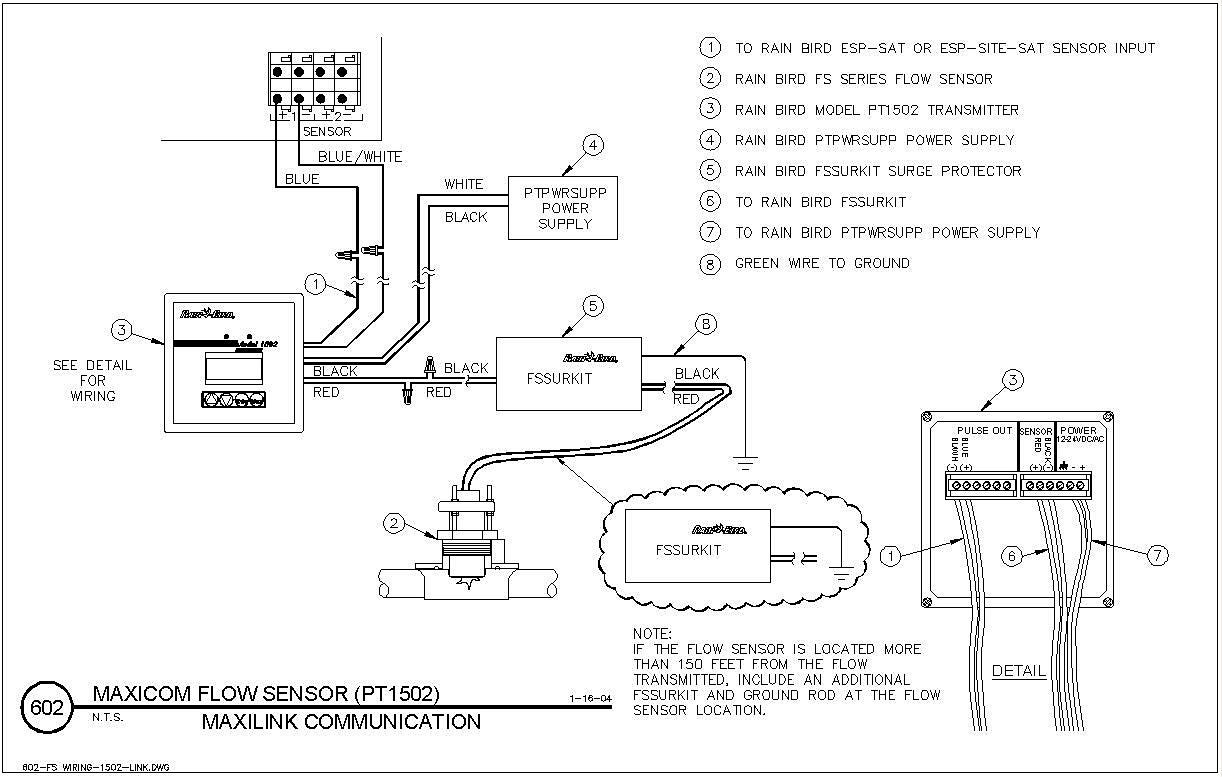
Flow Sensor Wiring, PT3002 Pulse Transmitter, Link Secondary ...
RELAY FOR RAIN BIRD CONTROLLERS. CONTROLLER #1 M.V. V. COM. 24 VAC CONTROLLER #2 M.V. V. COM. PUMP START RELAY WIRES CONTROLLER #3 M.V. V. COM. 4 This wiring diagram shows us the wiring for four controllers wired to one pump starter, and one Common wire for all valves on all four controllers. If more than one controller.
RAIN BIRD TBOS-BT1 MANUAL Pdf Download | ManualsLib
How to Wire a Rain Bird Auto Sprinkler Valve. Rain Bird's automatic irrigation systems eliminate the need to drag hoses and sprinklers around the yard, saving time and water with their efficient ...

FD-202TURF Decoder Wiring Diagram - Two Solenoids per Address ...
Please download these rainbird sprinkler wiring diagram by using the download button, or right click selected image, then use Save Image menu. Wiring diagrams help technicians to view how the controls are wired to the system. Many people can read and understand schematics generally known as label or line diagrams.
Par+ & MSC+ Installation Manual
The following diagrams show wiring details for pump start relay and pump motor starter wiring for various Rain Bird controllers. Figure 1: This is a basic pump. Manuals and User Guides for Rain Bird ESP-RZX. We have 1 Rain Bird ESP- RZX manual available for free PDF download: Installation Manual & Operation.
Need Help with Rainbird to Rachio wiring Model ESP-ME ...
Rainbird Esp-4tm Three Solinoid Wiring Diagram Forum discussion: I have a rain bird sprinkler system (ESP modular). It has 9 stations that 1st modular includes 4 stations while 2nd and 3 modular controls Had a mixture of bad valves, solenoids and wires [eaten through by.

Rain Bird SST Smart Sprinkler Timer - Installation
Mike Briley from Access Irrigation demonstrates how to wire a 24v irrigation solenoid valve into a mains powered irrigation watering controller using low vol...
Rainbird ESP Modular Controller Wiring Question : Home and ...
Cap these wires with a wire nut, as well. Connect the common wire from the multicore cable (usually white) to any of the three terminals on the controller marked COMMON. Step 4 Connect each of the other solenoid wires to one of the ZONE inputs. Rain bird solenoid wiring diagram moreover rain bird valves repair diagram further hydraulic solenoid ...

Rain Bird ESP-Modular Información del Producto | Manualzz
Law Enforcement send XXL or XXXL t-shirts to:GCI TurfPO Box 215Reidsville, NC 27323Email Sign Up To Win Free Lawn Care Stuff - http://eepurl.com/dHrFZf COOL ...

RainBird ESP-RZX Indoor Controller – Controlled Irrigation
07.06.2019 07.06.2019 4 Comments on Rainbird Wiring Diagram Does Rain Bird offer a wiring junction box? 7" round is a more . I need a replacement lid but Rain Bird does not offer that SKU or part number.
Rain Bird DV Valve Instructions
rain bird ssti wiring diagram for orbit pump start relay besides sensor also sstin review. rain bird ssti watering timers. call Rain Bird toll-free Technical Support at: RAIN BIRD () or visit diagramweb.net Connect an optional Rain Sensor to the Timer Remove the wiring bay cover at the bottom of the unit.
ELECTRICAL RATING CATALOG NUMBER DATE
Rainbird Valve Diagram. sprinkler or elevated piping in the circuit to meet most codes, (See Diagram. 1. ( Consult local building code.) CAUTION: Do not use this anti-siphon valve as a. Rain Bird valves provide . Rain Bird residential valves cannot be used with PRS pressure regulating modules controller out to the first valve on a circuit and.

Rain Bird SMRT-Y Soil Moisture Sensor Wiring Diagram | Manualzz
The following diagrams show wiring details for pump start relay and pump motor starter wiring for various Rain Bird controllers. Figure 1: This is a basic pump start wiring diagram for most controllers. This diagram assumes the Master Valve circuit is being utilized for the pump start circuit.
Any clue how to disconnect an old rainbird sprinkler system ...

Rain Bird ESP-6TM - iFixit

Amazon.com : Rain Bird SST400IN Simple-to-Set Indoor ...

Wireless irrigation control Patent Grant Tennyson , et al ...

FD-102TURF Decoder Wiring Diagram - Rain Bird Corporation ...

RAIN BIRD STP-400I INSTALLATION, PROGRAMMING & OPERATION ...

Rain Bird SST Indoor Controller Owner's Manual - Irrigation ...
Rainbird to Rachio IRO (Wiring Help) - Archive - Rachio Community
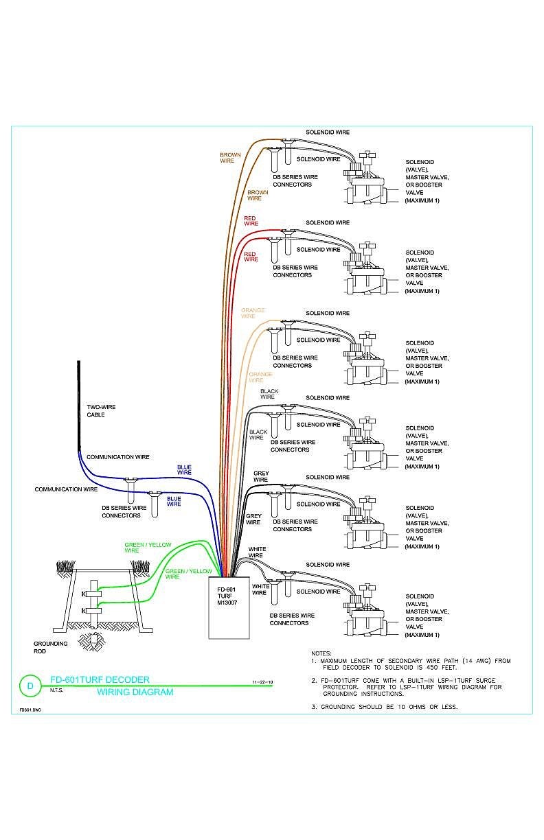
FD-601TURF Decoder Wiring Diagram | Rain Bird
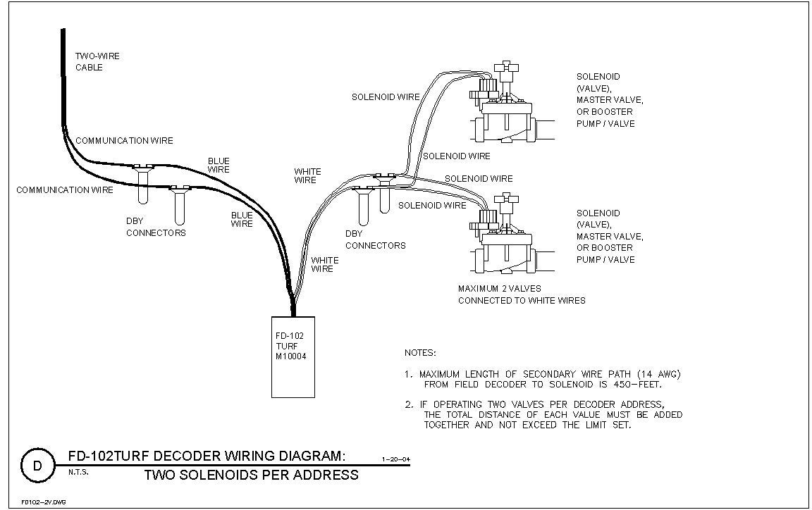
FD102TURF Field Decoder Wiring Diagram - Two Valves and ...
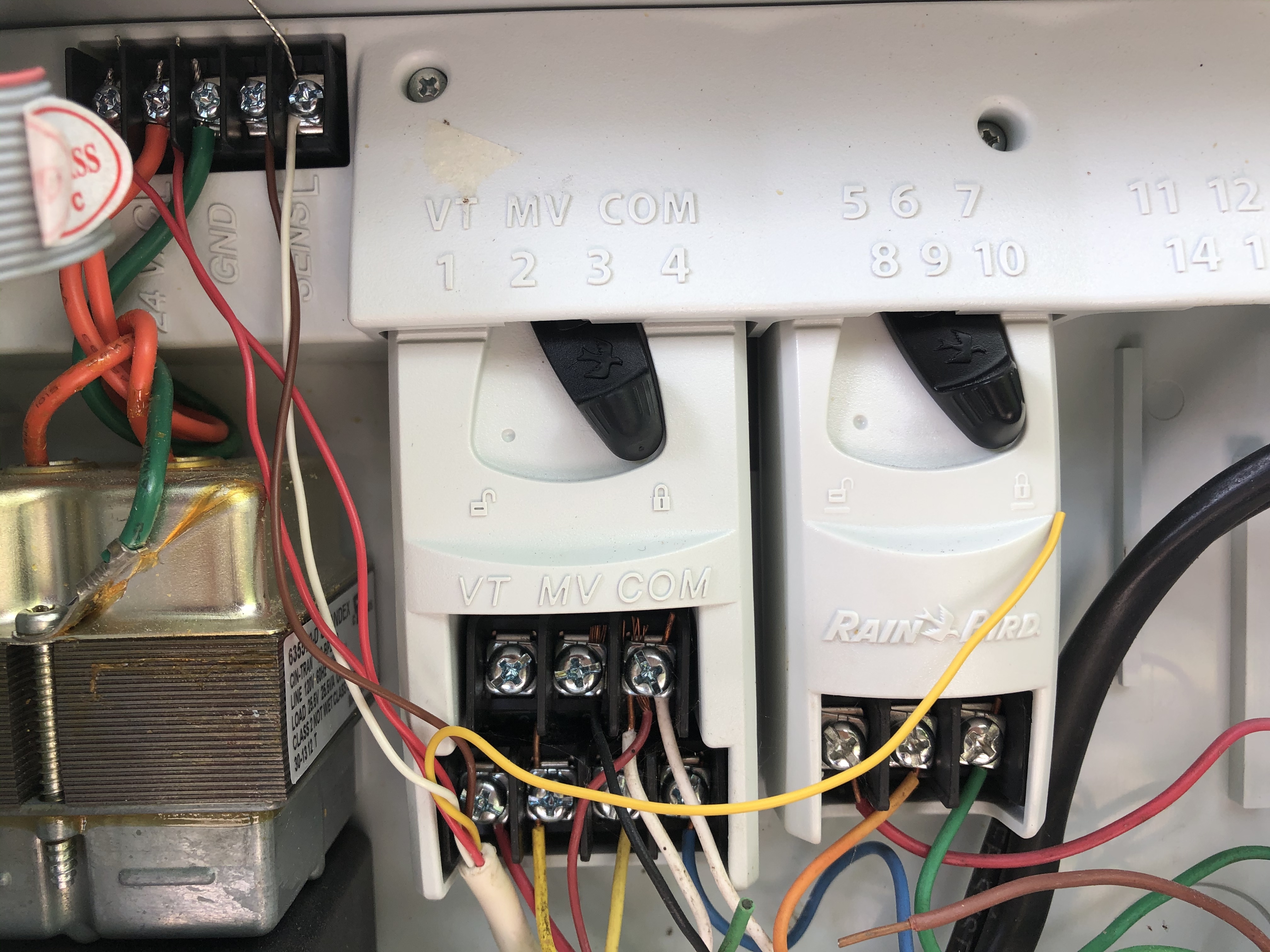
Rainbird ESP-Me to Rachio 3 - Wiring - Rachio Community
Rain Bird E-Class User Manual
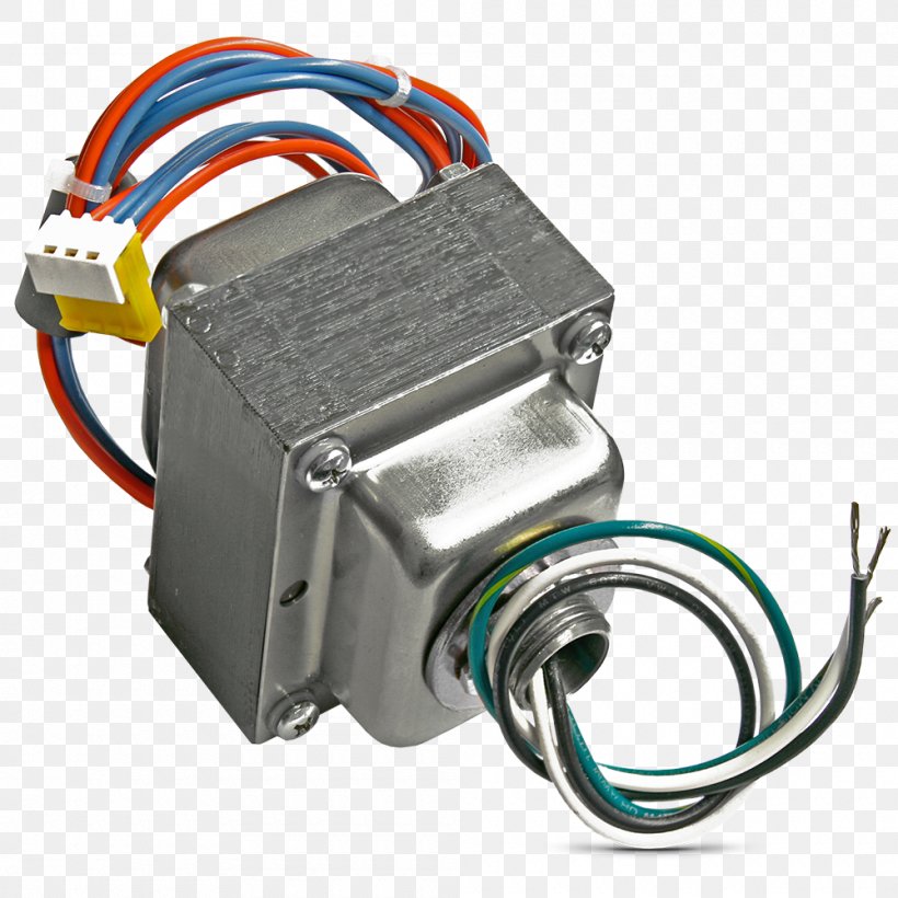
Electronic Component Wiring Diagram Transformer Electronics ...
The Paige Irrigation Wiring Guide for Decoder Systems

Rain Bird CP100 1 in. In-Line Irrigation Valve Full Product ...

Using the Rainbird with Pump Start Relay for Ebb and Flow Tables in Greenhouse
X-Core - Connecting a Master Valve | Hunter Industries
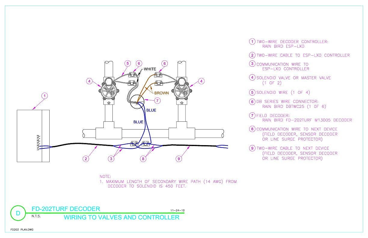
FD-202TURF Decoder Wiring to Valve and Controller | Rain Bird

How to Replace a Lawn Sprinkler Timer: 12 Steps (with Pictures)
Wiring Diagram Electronics Electrical Network Rain Bird ...
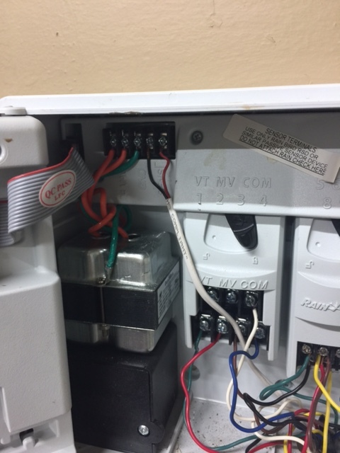
Need Help with Rainbird to Rachio wiring Model ESP-ME ...
Alarm on rain bird - not working : Home and Garden : r/Irrigation
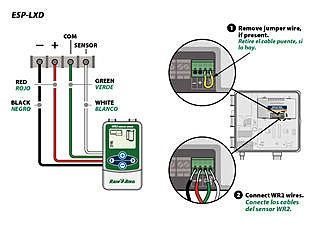
WR2 wiring diagram for Rain Bird ESP-LXD controllers
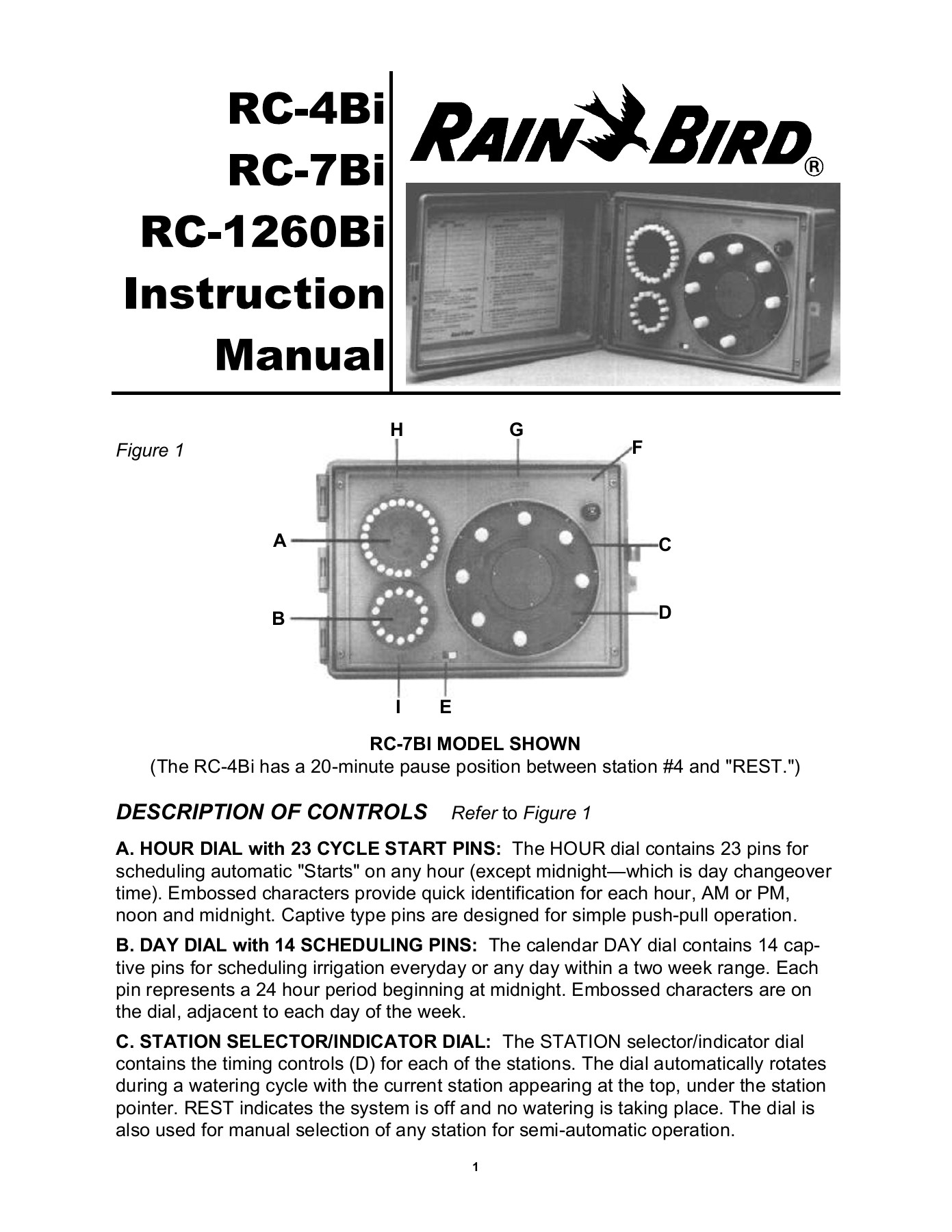
RC-4Bi RC-7Bi RC-1260Bi Instruction Manual - Rain Bird
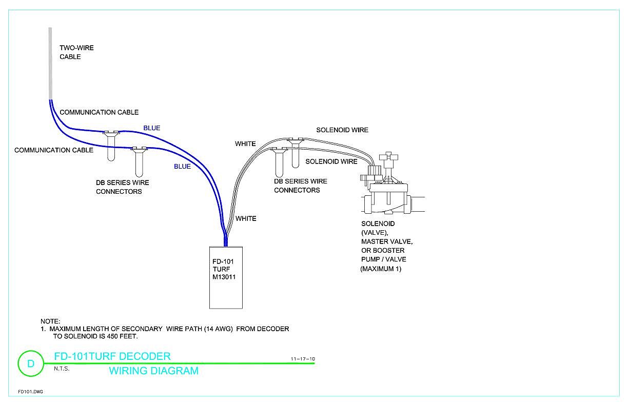
FD-101TURF Decoder Wiring Diagram | Rain Bird
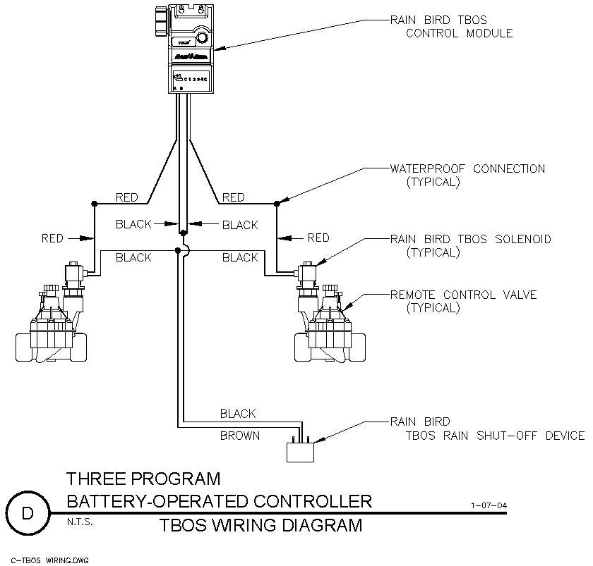
TBOS Wiring | Rain Bird

Wiring A Sprinkler System - RainBird ESP-Me Irrigation Timer
Comments
Post a Comment