41 Electromagnet Circuit Diagram
Electric Vehicle Schematic Diagram - U Wiring An electric car simply consists of three main components Battery controller and electric motor. Automotive wiring types of terminals and wiring diagrams. Automotive Cooling Wiring Diagram In 2021 Car Mechanic Electricity Automotive Repair They will last for a minimum of 25000 miles. Electric vehicle schematic diagram. A car wiring diagram is a map. Find out […] Circuit Diagram - Learn Everything About Circuit Diagrams A circuit diagram is a visual display of an electrical circuit using either basic images of parts or industry standard symbols. Symbol usage depends on the audience viewing the diagram. These two different types of circuit diagrams are called pictorial (using basic images) or schematic style (using industry standard symbols).
An electromagnet is the most powerful type of magnet there ... 8.2.2021 · An electromagnet is the most powerful type of ... 4.Elections are moved thorough a circuit creating that current interacts with a magnet moving the conductor ... a. An iron rod is held up by a magnet. The magnet is held up by a string (from a ceiling, let's say). Draw a free-body diagram for the magnet and a separate free-body

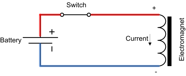
Electromagnet circuit diagram
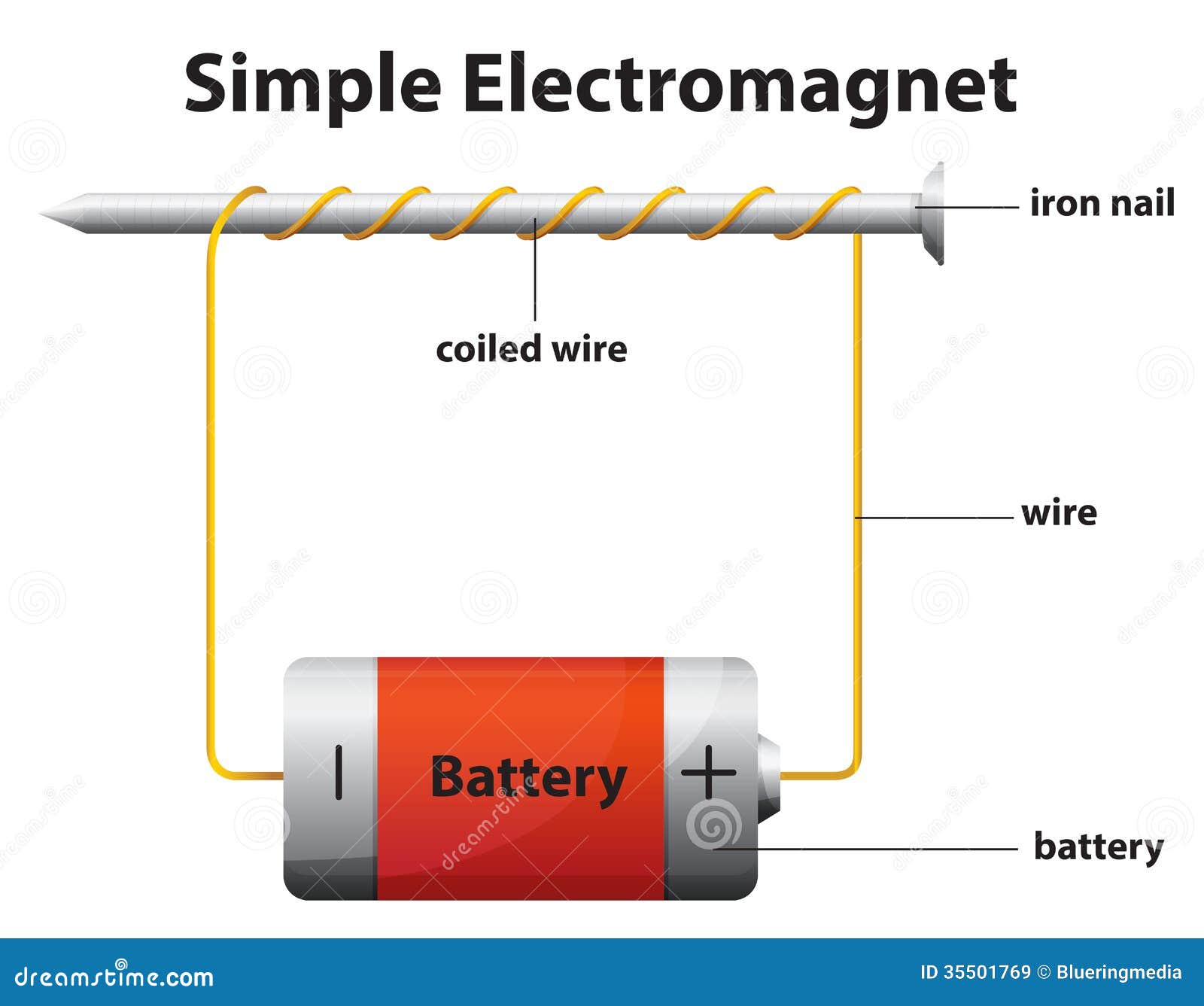
What is the circuit diagram for an electromagnet? - Answers An electromagnet consists basically of a piece of metal surrounded by a coil of wire, which is connected to a power source. The simplest form would be an iron rod which has a piece of wire wrapped... PDF Typical Electrical Drawing Symbols and Conventions. Basics 7 4.16 kV 3-Line Diagram : Basics 8 AOV Elementary & Block Diagram : Basics 9 4.16 kV Pump Schematic : Basics 10 480 V Pump Schematic : Basics 11 MOV Schematic (with Block included) Basics 12 12-/208 VAC Panel Diagram : Basics 13 Valve Limit Switch Legend : Basics 14 AOV Schematic (with Block included) Basics 15 Wiring (or Connection ... Electromagnet Circuit Diagram | Wiring Diagram Image Jul 06, 2018 · Electromagnet Circuit Diagram. – Delightful in order to the blog, in this particular time period I will demonstrate with regards to electromagnet circuit diagram. . And now, this is the initial image: Diagram An Electromagnet Download from electromagnet circuit diagram , source:visithoustontexas.org. Diagram An Electromagnet Download from ...
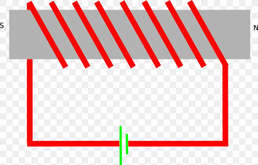
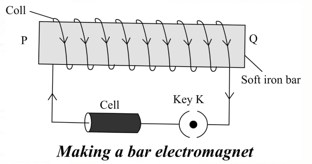
Electromagnet circuit diagram. Circuit diagram symbol for an electromagnet | Physics Forums Circuit diagram symbol for an electromagnet Thread starter Iceman123; Start date Jun 18, 2006; Jun 18, 2006 #1 Iceman123. 11 0. Is there a circuit diagram symbol for an electromagnet? Am I correct in thinking that it is a line with a coil going round it? I have looked all over the web, and cannot find confirmation of this. Electrical And Electronic Symbols | Electrical4U 24.2.2012 · There are many electrical and circuit symbols used internationally around the world. While they are mostly standardized (i.e. the same electronic symbols are used in different countries), you will still find some international differences. Below is a table of the most commonly used electrical symbols used in circuit diagrams. What is an electromagnet? Draw a circuit diagram to show how ... Draw a circuit diagram to show how a soft iron piece can be transformed into an electromagnet. Medium Solution Verified by Toppr The magnetic field produced due to current flowing in a coil or a solenoid can be used to magnetise a material like soft iron temporarily. The insulated copper wire is warpped on a soft iron piece. Medium Voltage Circuit Breaker Course Chapter 3.0 Student ... Medium Voltage Circuit Breaker Course Chapter 3.0 Student ... We will be using this diagram to discuss the following electrical operating sequence of a circuit breaker. ... an electromagnet which produce eddy currents in the disk or cup generating torque on the moveable rotor.
House Wiring Diagram - Everything You Need to Know ... A wiring diagram is a pictorial representation of an electric circuit, where the elements of the loop and the signal connections between devices and the power source are shown in the conventional methods as simplified shapes. A house wiring diagram is thus, a wiring diagram of a house. Circuit Diagram | Electricity | Electric Circuit - LabInApp Circuit Diagram We know that an electric circuit comprises of different components like cell or battery, electrical components, connecting wires, etc. The way to represent a circuit is through a schematic diagram, in which different components are represented with symbols. Wiring Diagram - Everything You Need to Know About Wiring ... What is a Wiring Diagram? A wiring diagram is a simple visual representation of the physical connections and physical layout of an electrical system or circuit. It shows how the electrical wires are interconnected and can also show where fixtures and components may be connected to the system. When and How to Use a Wiring Diagram Difference between Schematics and Circuit Diagrams - Edraw A circuit diagram (also named electrical diagram, elementary diagram, and electronic schematic) is a graphical representation of an electrical circuit. Circuit diagrams are widely used for circuit design, construction, and maintenance of electrical and electronic equipment.
Simple Electric Circuit Diagram, Electronic Circuit ... The blown fuse indicator circuit. 230v Live wire scanner/tester. This is another electric tester circuit that detects the signal from touching the sensor wire over the cover of wires. Use only Battery for this circuit. The following electronic circuit diagrams very Simple, useful, and can be made by any beginner. Circuit Diagram - A Circuit Diagram Maker Circuit Diagram A free, user-friendly program for making electronic circuit diagrams. Get Started Design Create diagrams visually by placing components with your cursor. Extend the built-in functionality with custom components. Render Export circuits as scalable vector images, or convert to a selection of other formats. Simulate Draw A Circuit Diagram Of An Electromagnet - Wiring Diagram Line Feb 14, 2022 · 6 basic schematic diagram of the electromagnet driver circuit which scientific what is an draw a to show iron can be changed into bya solenoid science magnetic ... Electric circuit diagram - BrainKart Electric circuit diagram. To represent an electrical wiring or solve problem involving electric circuits, the circuit diagrams are made. The four main components of any circuits namely the, (i) cell, (ii) connecting wire, (iii) switch and (iv) resistor or load are given above.
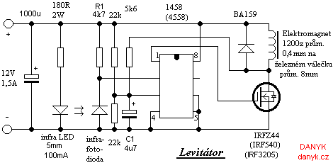
Electromagnetic levitation device
A Circuit Diagram Of An Electromagnet - Wiring View And ... Jan 01, 2018 · The Electric Circuit Diagram Of A Fl With Electromagnetic Ballast Scientific. 6 basic schematic diagram of the circuit electromagnets teacher notes a draw to show how electromagnet adjule electromagnetic actuator gr7 technology soft iron bar as an coils work excel physics class 12 cbse circuitry digital computer tesla coil electronic electronics pololu forum electric fl grade 7 topic ...
Electromagnet Diagram Stock Illustrations – 106 Electromagnet ...
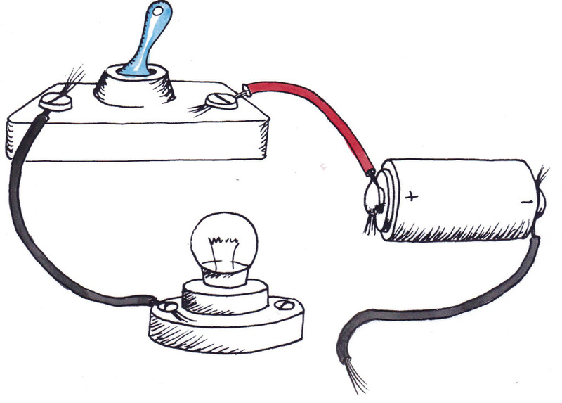
Electric Circuit Diagrams: Lesson for Kids - Video ... This simple circuit has four parts: the switch, the battery (which is the source of the electricity), the light bulb, and the wire through which the electricity flows. Electric circuit diagrams...

What is an electromagnet? On factors does the strength of an ...
Electric Circuit - Introduction, Types, Diagram and ... Domestic Electric Circuit. The above figure represents the domestic circuit diagram. The electric power that we receive in our houses is by the main supply, commonly called mains. It is supplied by either overhead cables or by underground cables. There are 3 types of wires in domestic circuits and are Earth Wire, Live Wire, and Neutral Wire.
Physical Experience Using Electromagnet Changing Current ...
Residential Electrical Wiring Diagrams The kitchen electric range may also be found to have a 3-wire or 4-wire cord or 220 volt outlet which will require proper electrical connections and wiring as found in the diagrams and instructions. Most Arc Welders require a dedicated electrical circuit and 220 volt outlet that is sized according to the specifications of the welder as ...
Difference Between Electromagnet and Permanent Magnet (with ...
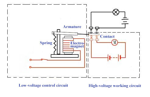
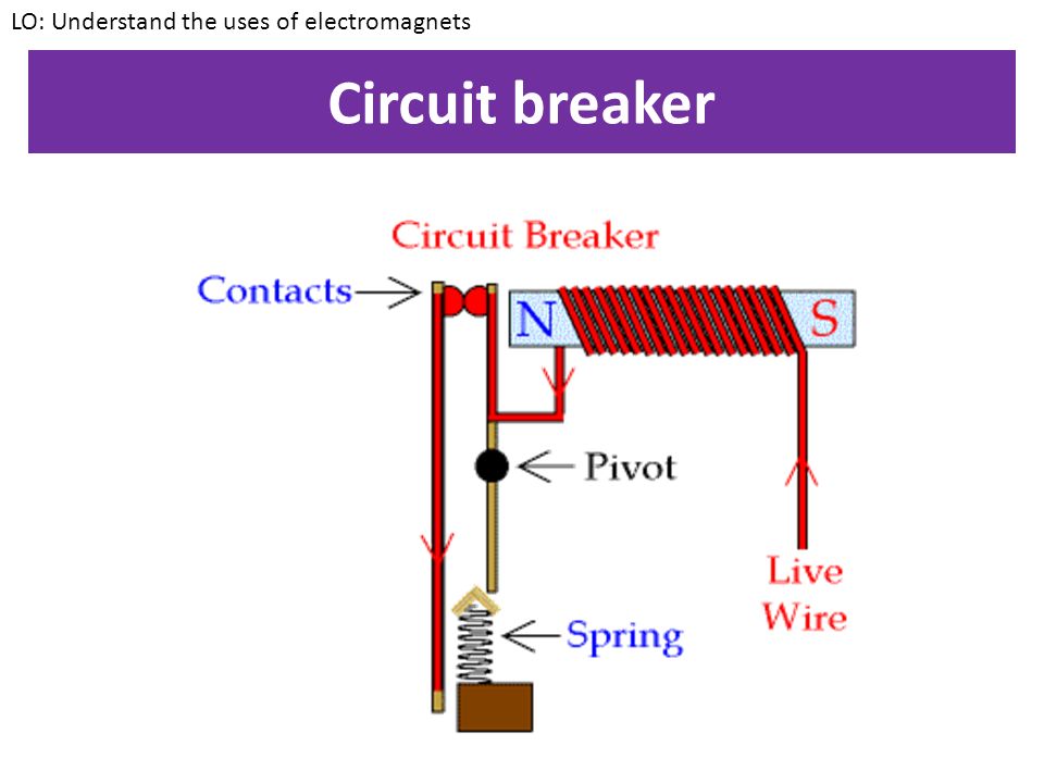
Electromagnets - Electromagnets and motors - BBC Bitesize They use an electromagnet, often to control a high-power circuit using a low-power signal or where multiple circuits need to be controlled by one circuit. previous 1
Electromagnet Stock Illustrations – 872 Electromagnet Stock ...
PDF Electrical Symbols and Line Diagrams - University of Florida A line (ladder) diagram is a diagram that shows the logic of an electrical circuit or system using standard symbols. A line diagram is used to show the relationship between circuits and their components but not the actual location of the components. Line diagrams provide a fast, easy understanding of the connections and use of components.
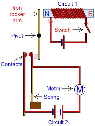
GCSE PHYSICS - How does a Relay Work? - Why is a Relay Used ...
Circuit Diagram And Its Components - Explanation With ... A circuit diagram is a graphical representation of an electrical circuit. A circuit diagram also called an electrical diagram, elementary diagram or electronic schematic is defined as a simplified graphical representation of an electrical circuit.

Faraday's Laws of Electromagnetic Induction: First & Second ...
Draw a labelled diagram to show how an electromagnet is made. Show with the aid of a diagram how a wire is wound on a U-shaped piece of soft iron in order to make it an electromagnet. Complete the circuit diagram and label the poles of the electromagnet. Hard. View solution > How is an electromagnet made? Name two factors on which the strength of the magnetic field of an electromagnet depends.
![Electromagnetic Levitation Circuit [Anti-gravity] - Homemade ...](https://www.homemade-circuits.com/wp-content/uploads/2021/05/electromagnetic-levitation-circuit-diagram.png)
Electromagnetic Levitation Circuit [Anti-gravity] - Homemade ...
Making an Adjustable Electromagnet Circuit - Homemade Circuit ... Aug 22, 2019 · The electromagnet may be procured ready made or can be hand made at home using suitable lengths of enameled copper wire wound over a magnetic core, like an iron nail or rod etc. The diode connected across the electromagnet protects the transistor from back emf fluxes of the electromagnet. The circuit may be powered with voltages between 5 and ...
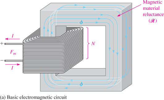
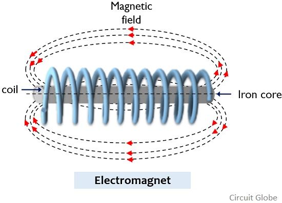
Basic Electromagnetic Circuit and Electromagnet | Electrical A2Z
What Is Electric Circuit With Symbols, And Formulas Used Electric Circuit Symbols. Every component and product of the electric circuit contains a symbol. The symbols represent parts of the circuit in a circuit diagram. Beneath are the basic set of symbols that are present in a circuit diagram. Simple Circuit. A simple circuit comprises the power source, conductors, switch, and load. Cell: It is the ...
Application of Electromagnet - Excel@Physics
10 Simple Electric Circuits with Diagrams - Bright Hub ... An electric circuit is a closed loop with a continuous flow of electric current from the power supply to the load. Here are ten simple electric circuits commonly found around the home. Electric circuits like AC lighting circuit, battery charging circuit, energy meter, switch circuit, air conditioning circuit, thermocouple circuit, DC lighting circuit, multimeter circuit, current transformer ...

6: Basic schematic diagram of the electromagnet driver ...
Schematic Diagram - A Complete Tutorial with Free Examples ... A schematic diagram is a visual representation of a project plan that is prepared using lines and generic icons to keep the drawing extremely simple and easily understandable. Although schematic diagrams are usually prepared for electrical and electronic projects, they are not limited to those domains and can be created for many other industries such as building and constructions, chemistry ...

Electromagnet Circuit - Electrical Engineering Stack Exchange
Dishwasher Wiring Diagram, Schematic & Cycle Not Advancing Using the diagram and chart in figure 6-D, lets say we want to test switch "A." We see that with button number 1 pressed, only switches "A" and "D" inside the switchblock are closed. ... When the motor starts, the electromagnet stops, and the …
Back EMF Suppression | Progeny Access Control
Simple Circuit Diagram Of An Electromagnet - Basic Wiring Diagram electromagnet circuit diagram wiring diagram image. 7 6 2018 electromagnet circuit diagram cute in order to the blog in this particular time become old i will campaign with regards to electromagnet circuit diagramand now this is the initial image. what is an electromagnet describe the sarthaks econnect.

Electronic symbol Electromagnetic coil Inductor Wiring ...
Physics Tutorial: Circuit Symbols and Circuit Diagrams A final means of describing an electric circuit is by use of conventional circuit symbols to provide a schematic diagram of the circuit and its components. Some circuit symbols used in schematic diagrams are shown below. A single cell or other power source is represented by a long and a short parallel line.

a Draw a circuit diagram to show how a soft iron piece can be ...
Electric Circuit Diagram on the App Store "Electric Circuit Diagram" app brings to you a guided tour to acquaint yourself with the lab experiment that demonstrates about electric circuit diagram. The app brings to your finger tip the step by step protocol for the experiment. The "Electric Circuit Diagram" exhibits all the apparatus required…

(a) Draw a circuit diagram to show how a soft iron piece can be transformed into an electromagnet
Electromagnet Circuit Diagram | Wiring Diagram Image Jul 06, 2018 · Electromagnet Circuit Diagram. – Delightful in order to the blog, in this particular time period I will demonstrate with regards to electromagnet circuit diagram. . And now, this is the initial image: Diagram An Electromagnet Download from electromagnet circuit diagram , source:visithoustontexas.org. Diagram An Electromagnet Download from ...
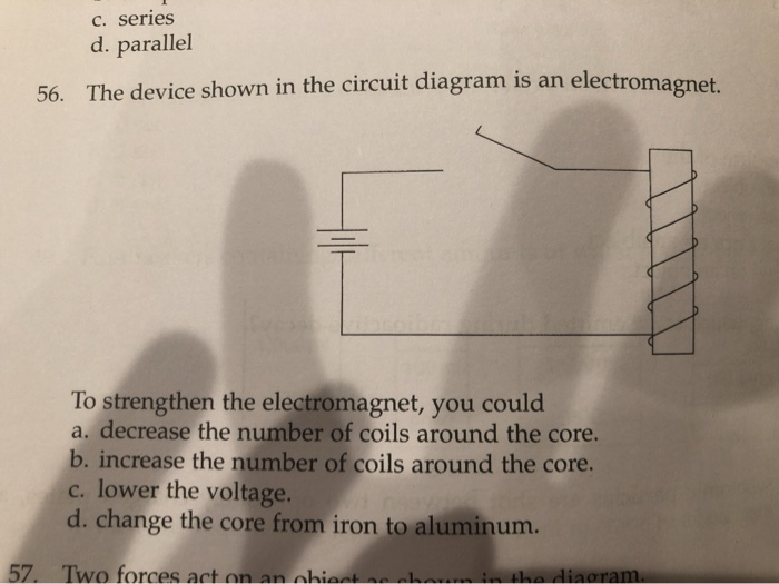
Solved C. series d. parallel 56. The device shown in the ...
PDF Typical Electrical Drawing Symbols and Conventions. Basics 7 4.16 kV 3-Line Diagram : Basics 8 AOV Elementary & Block Diagram : Basics 9 4.16 kV Pump Schematic : Basics 10 480 V Pump Schematic : Basics 11 MOV Schematic (with Block included) Basics 12 12-/208 VAC Panel Diagram : Basics 13 Valve Limit Switch Legend : Basics 14 AOV Schematic (with Block included) Basics 15 Wiring (or Connection ...
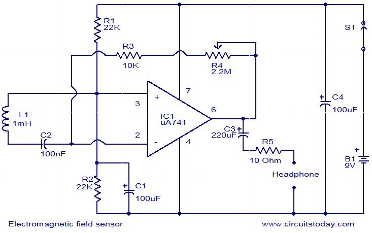
Electromagnetic field sensor circuit
What is the circuit diagram for an electromagnet? - Answers An electromagnet consists basically of a piece of metal surrounded by a coil of wire, which is connected to a power source. The simplest form would be an iron rod which has a piece of wire wrapped...

Electromagnet Diagram Stock Illustrations – 106 Electromagnet ...

Electromagnet not functioning - Project Guidance - Arduino Forum
Electromagnetic Relay Working Principle & Testing | ATO.com
Prototype Implementation of Electromagnetic Piston
Questions on resistance, electromagnets, power | EEWeb Community

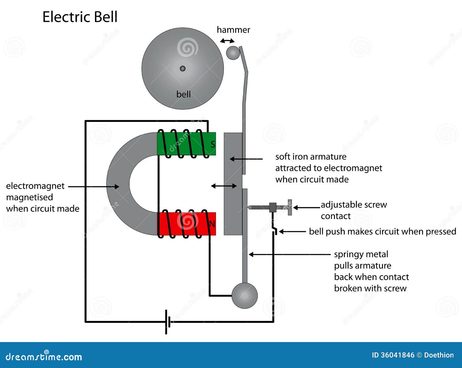
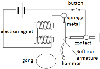
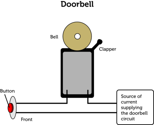
Electric bell (Construction and working mechanism) - Online ...
Electromagnet - VanCleave's Science Fun

Electromagnetic actuator circuit diagram. | Download ...

OLCreate: TESSA_STP Module 3: Science – energy and movement ...

Electromagnetic Pendulum Help : r/AskElectronics
Gr7 Technology
An electromagnetic levitation train, such as shown in | Chegg.com

Draw a circuit diagram to show how a soft iron piece can be ...
Wiring Diagram Electromagnet Circuit Diagram Drawing, PNG ...
How are electromagnets used in everyday life? What are some ...

The electric circuit diagram of a FL with electromagnetic ...
Draw a labelled diagram to show how an electromagnet class 12 ...

Electromagnetic Levitation Device : 5 Steps (with Pictures ...

Electromagnets by Ron Kurtus - Physics Lessons: School for ...
LO: Understand the uses of electromagnets - ppt video online ...
What is an electromagnet? Draw a circuit diagram to show how ...
Using Electromagnetism | CK-12 Foundation
Comments
Post a Comment