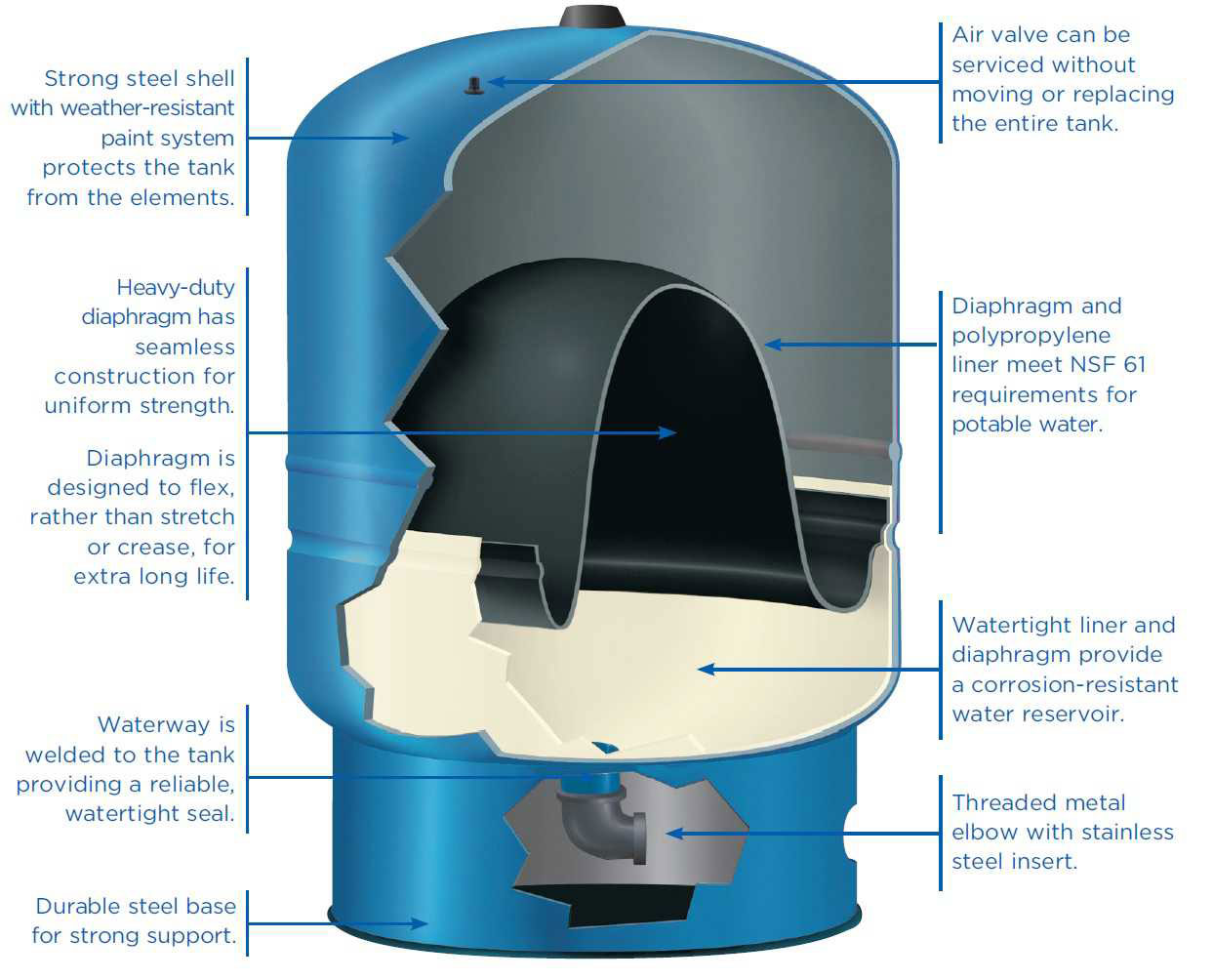
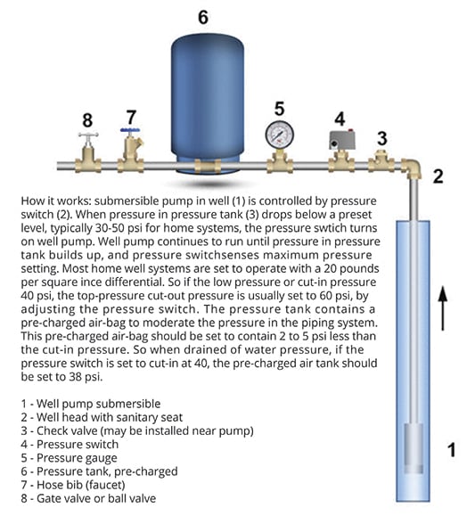
39 Well Pressure Tank Diagram
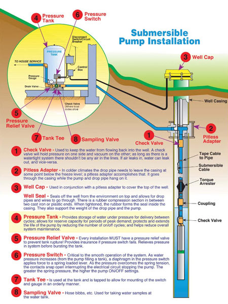
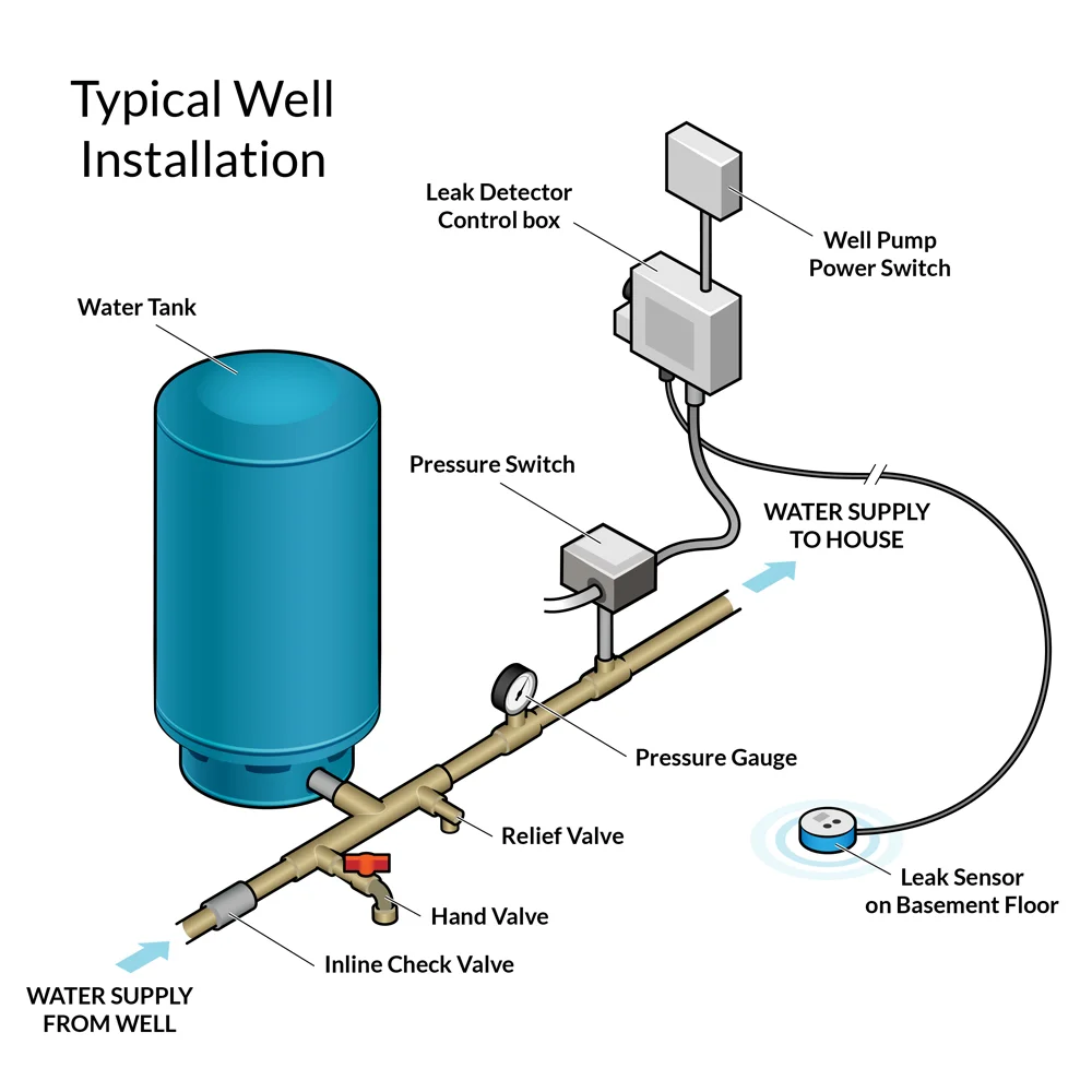
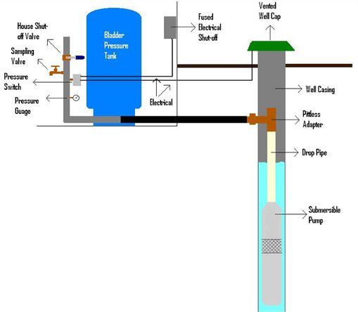
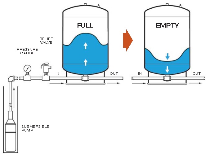
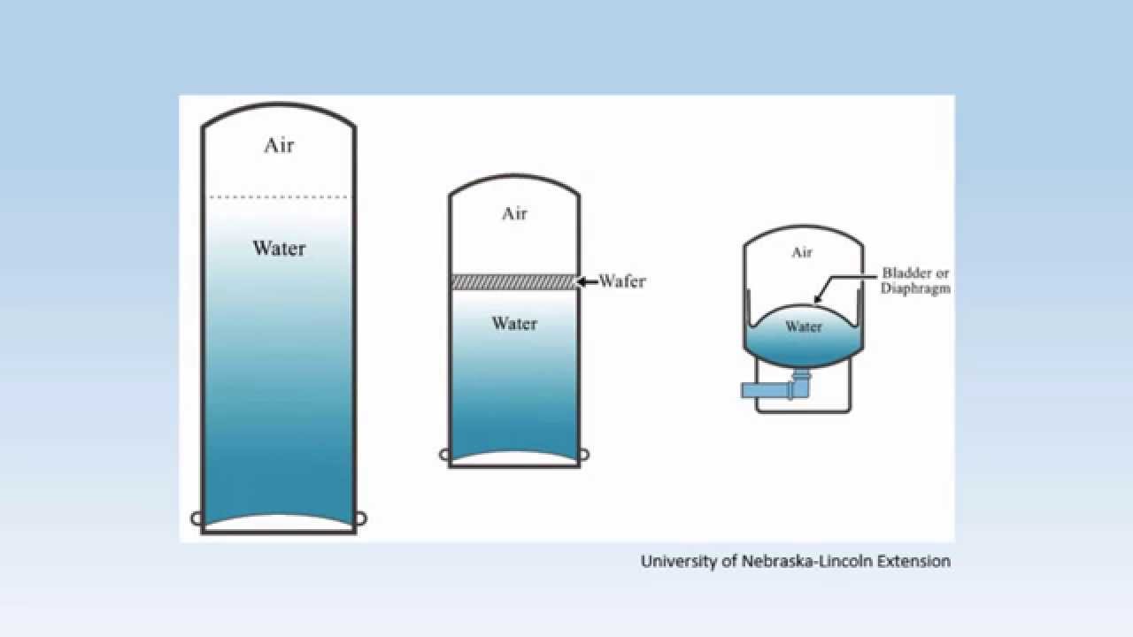
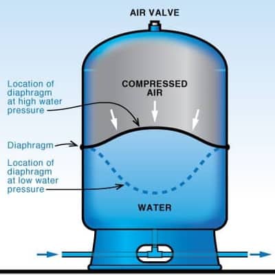
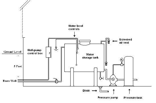
How a Well Pressure Tank Works - with Diagrams ... Water Pressure Tank Installation Diagram. The image below shows the typical installation diagram of a well pressure tank, as well as other components of a well system. Image: Lakeland Water Pump How a Bladder Pressure Tank Works. A bladder pressure tank is a steel tank with a bladder inside which looks like a balloon. Well Pump & Pressure Tank Diagram 6. Well Seal. Provides a positive seal inside the casing in above-ground installations. 7. Check Valve. Installed near the tank inlet to hold water in the tank during pump installation when the pump is idle. 8. Tank Tee. Connects water line from the pump to pressure tank and service line from tank to house.
Photo Guide to Well Water Pump Controls & Switches We discuss these well or water pump control questions: What are the functions of the well water pump pressure control switch, water tank relief valve, ...
Well pressure tank diagram
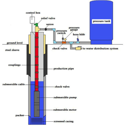
Well Diagram - Baker Water Systems PRESSURE GAUGE. (Section R) Measures water pressure in Pressure Tank. PRESSURE SWITCH. (Section S) Signals the pump to start when the water system ... Well Pressure Tank diagram - Lakeland Water Pump Co. Well Pressure Tank diagram. Well Pressure Tank diagram. Contact Us. Lakeland Water Pump Co. Hopatcong, NJ 07843. Phone: (973) 398-4444 ... Well Water Diagram |Well > Pressure Tank > Storage Tank ... Nitrate Filter Diagrams. Phosphate Systems. Reverse Osmosis. Sediment Filters. Soda Ash Systems. Tannin Filters. Ultraviolet Sterilizer Systems. Ultra-Filtration Systems. Well & Storage Tanks.
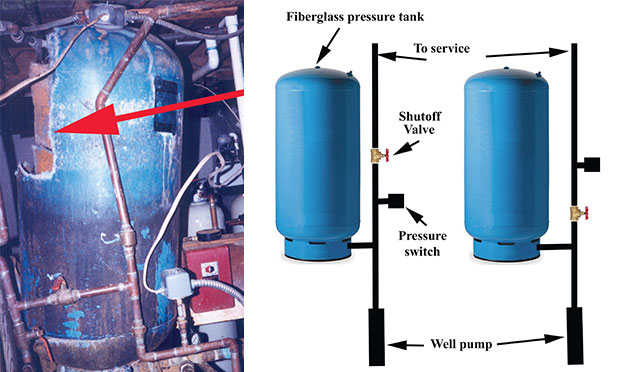
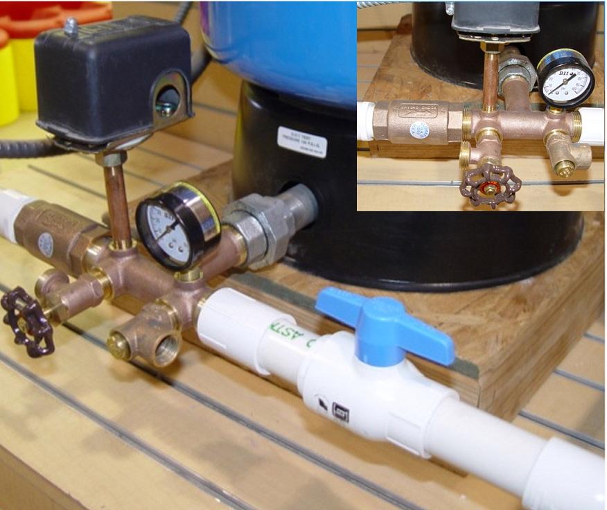
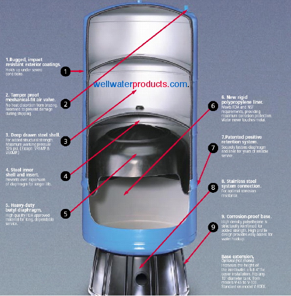
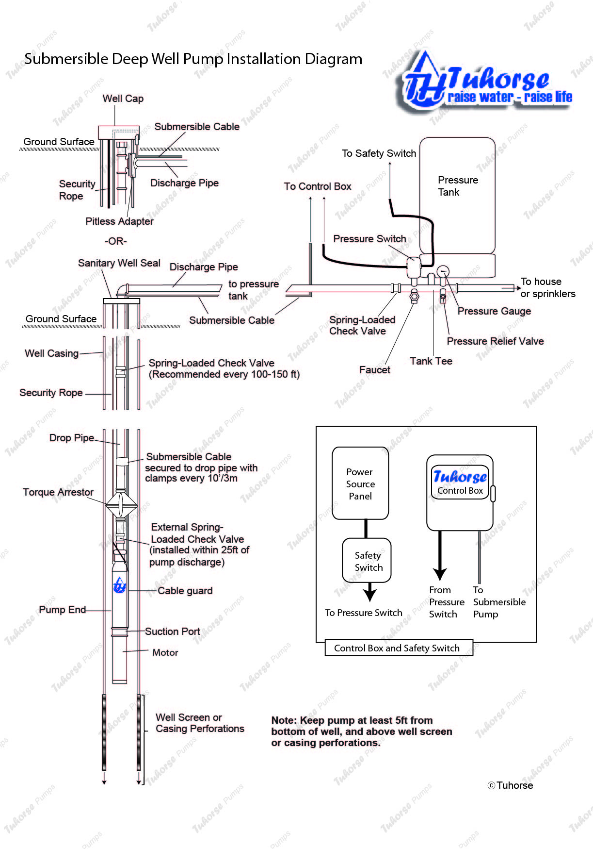
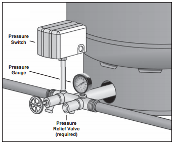
Well pressure tank diagram. Well Pump & Pressure Tank Diagram - Clean Water Store Well Pump & Pressure Tank Diagram PRESSURE TANK FROST LINE CASING Above Ground Installation 1 2 4 5 6 8 7 9 10 11 12 13 15 16 14 PUMP 3 1. Check Valve Located at the top of the pump to prevent back flow into pump and hold the head of water in the system. 2. Torque Arrestor Installed directly above Submersible Pump to protect pump and well components from starting torque damage. 3. Safety Rope Installation Manual DIAPHRAGM WELL TANK Thread tank tee into pressure tank so that the two 1/4” holes in the tee face upward. Thread street tee into front of tank tee. ˘ = Thread 3/4” male PVC adapter into the inlet side of tank tee. ˘ = Thread pressure relief valve into top of street tee. Thread 1/2” boiler drain into front of street tee. Cut and cement as many sections and Pump Pressure Tanks, how they work and how to set them. 12 Jul 2014 — The humble pressure tank is a very misunderstood part of your ... As well as that, most house pumps these days also are controlled by ... Well Pressure Tank Installation | The Home Depot - YouTube This well pressure tank installation video shows the steps you'll need for this replacement. Be sure to follow the proper requirements listed below and in th...
Well Water Diagram |Well > Pressure Tank > Storage Tank ... Nitrate Filter Diagrams. Phosphate Systems. Reverse Osmosis. Sediment Filters. Soda Ash Systems. Tannin Filters. Ultraviolet Sterilizer Systems. Ultra-Filtration Systems. Well & Storage Tanks. Well Pressure Tank diagram - Lakeland Water Pump Co. Well Pressure Tank diagram. Well Pressure Tank diagram. Contact Us. Lakeland Water Pump Co. Hopatcong, NJ 07843. Phone: (973) 398-4444 ... Well Diagram - Baker Water Systems PRESSURE GAUGE. (Section R) Measures water pressure in Pressure Tank. PRESSURE SWITCH. (Section S) Signals the pump to start when the water system ...
Submersible Well Pumps Service | Tri County Pumps | MD, VA. WV
Analysis of a domestic water tank failure | PropertyCasualty360

How a Well Pressure Tank Works - with Diagrams - Plumbing Sniper

How Does A Well Pump and Pressure Tank Work
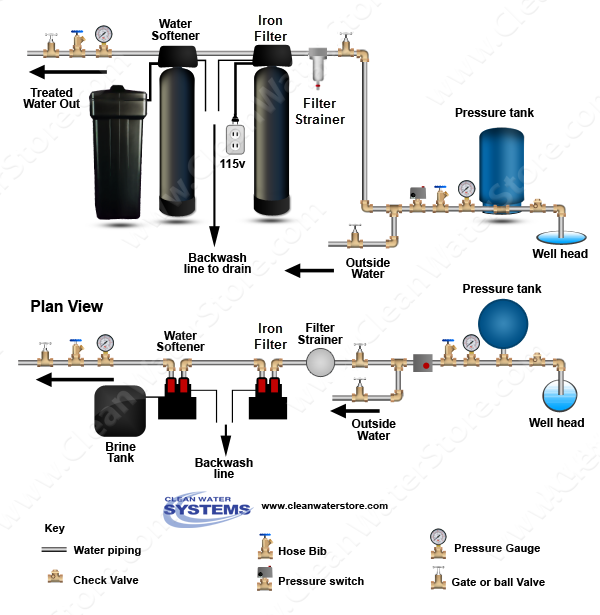
Where Should an Iron Filter Be Placed: Before or After the ...

Clean Well Water Report: Where Should An Iron Filter Be ...

Clean Well Water Report: Well Pump & Pressure Tank Diagram
Well head & pressure tank pictures / illustrations
Pressure Tank Thud at empty | Terry Love Plumbing Advice ...
Leak Defender RS Installation Guide — Tec Innovators
Water Well Services | Well Pumps | Rockford, IL
Cross section of precharged (bladder) tank for a well pump system

Mr. Bills Pump & Well Service - Arlington, Marysville, the ...

Clean Well Water Report: Can I Increase My Pressure Tank Size ...
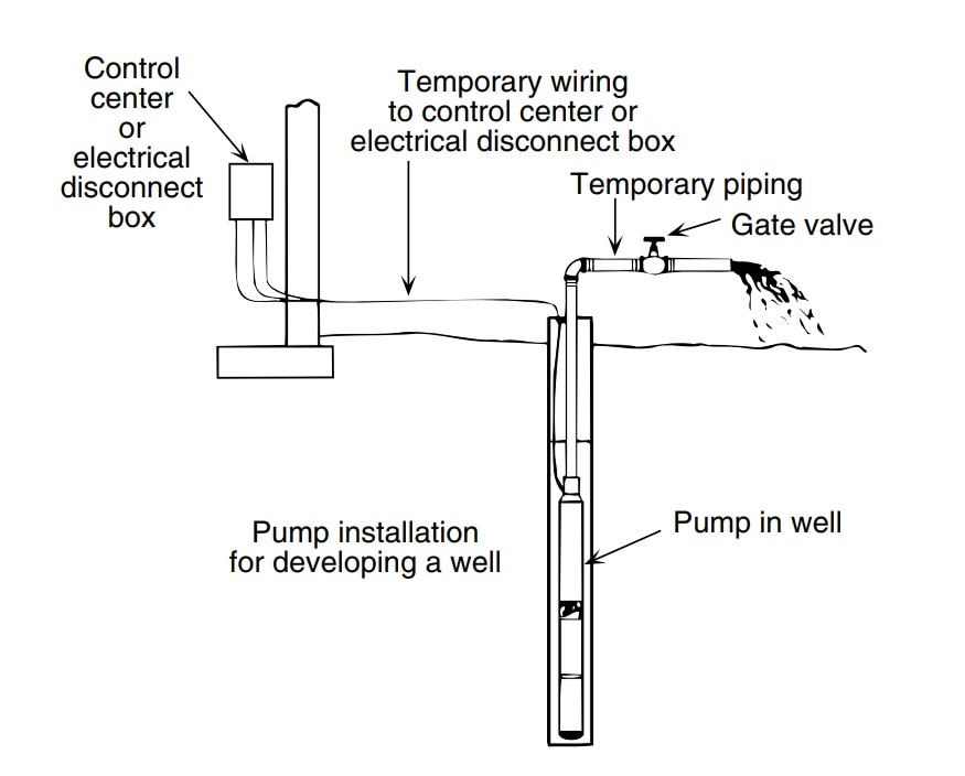
How to Install and Wire a Well Pump - Well Pump Installation ...
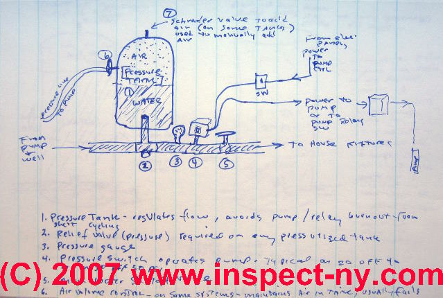
Photo Guide to Well Water Pump Controls & Switches - private ...
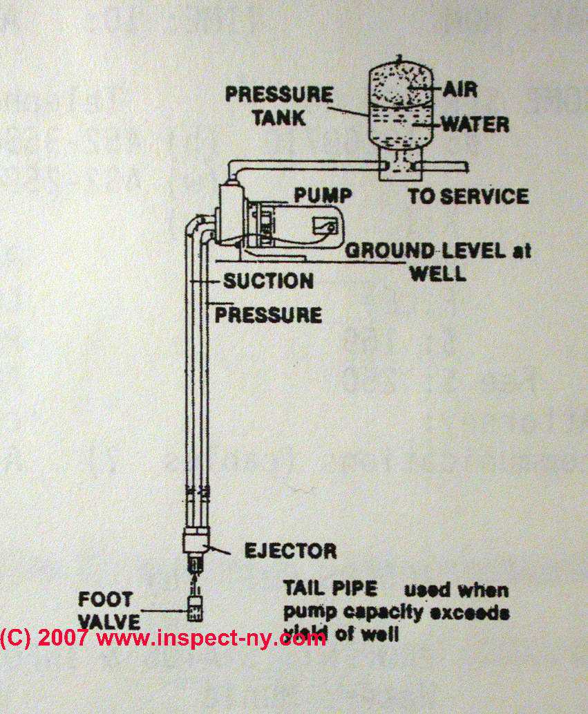
Two Line Jet Pumps for Water Wells: Installation & Repair ...
Waterlogged Pressure Tank | Poor Water Pressure Solutions
Water Well Problems? 7 Well Water Warning Signs How to ...
How Does My Private Well Pressure Tank Work?

Backup Water Systems | RPS Solar Pumps | America's #1 Solar ...
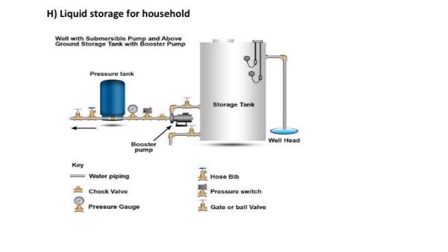
Solved H) Liquid storage for household Well with Submersible ...
Well Pressure Tanks | Water Pressure Up & Down | Well Water ...

Wellmate WM-6 Well Pressure Tank
Wire a three wire 120v well pump directly into pressure ...

Baker Water Systems - Well Diagram

Cleanwater Overview - Red Lion
Individual Water Supply Wells - Fact Sheet #2
Pump Installation
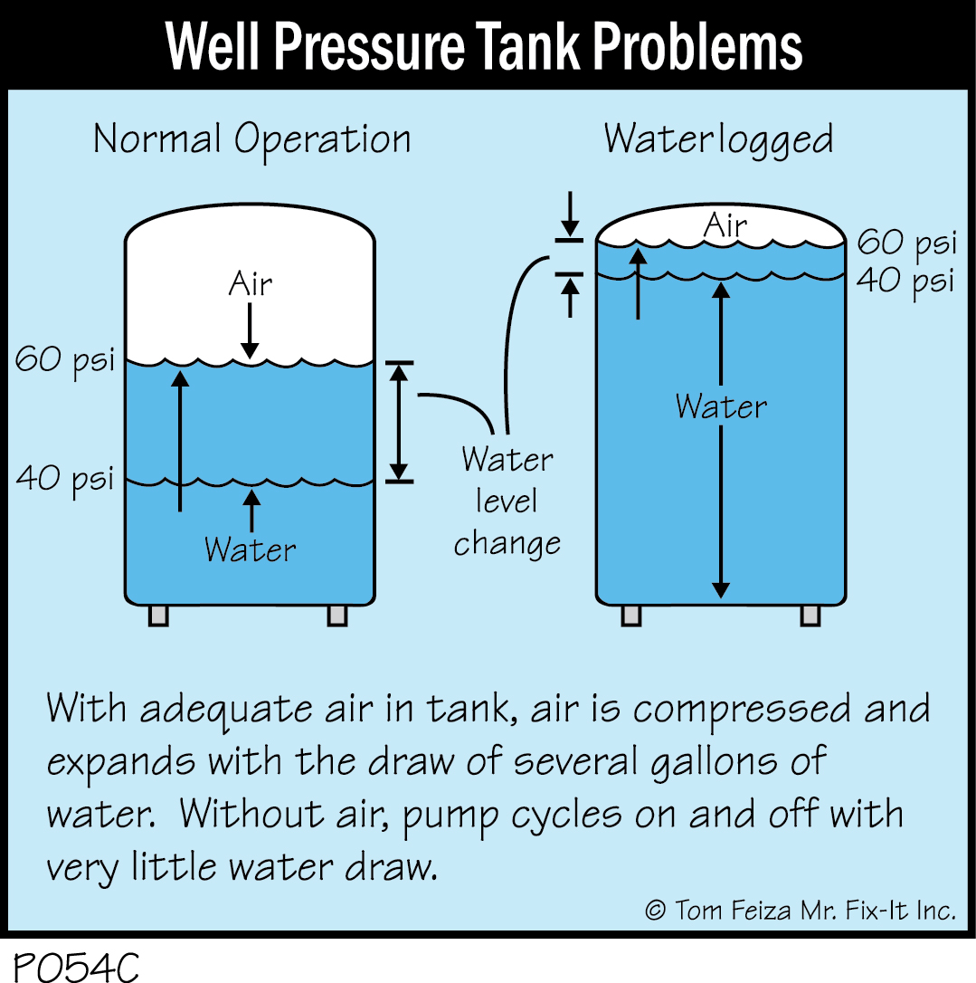
P054C - Well Pressure Tank Problems - Covered Bridge ...

Welcome to Joe Mumford Plumbing and Heating Company Online!

Well Diagrams

Amtrol Well-X-Trol 20 Gallon Underground Pressure Tank - WX ...

Horizontal Installation | Water Worker

Private Drinking Water Wells: The Distribution System
Standard Pressure Water Well - Bee Cave Drilling
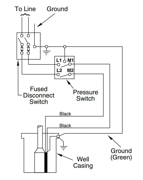
How to Install and Wire a Well Pump - Well Pump Installation ...
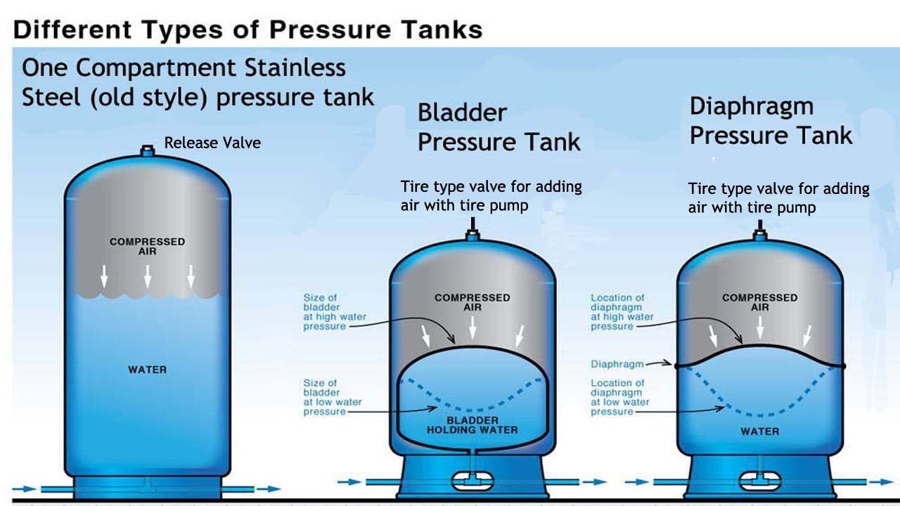
Pressure Tank Comparison - Pro's and Con's, Stainless, Bladder, Diaphragm
Well Pressure Tank Water Logged? | Home Well Water Tank Services
Comments
Post a Comment