39 ts diagram for air
- Air Refrigerator working on Bell-Coleman cycle with PV and TS diagram (reversed Brayton or Joule Cycle) - Mechanism and working of a vapour compression refrigeration system - with PV And TS diagram. In this video he has explained the concept of Bell Coleman air refrigeration cycle with PV and TS diagrams. He has also derived the COP equation. If you...
Oxygen Cycle - Learn what is the Oxygen Cycle, its meaning, the steps involved in the oxygen cycle with the help of a diagram, Co-dependence of Carbon Cycle, Hydrogen Cycle & Oxygen Cycle and more with BYJU'S.
Ts diagram for air
The Brayton or the Joule cycle is commonly used to analyze the gas turbine systems and the figure 2 shows a Temperature-Entropy (TS) diagram representation of an ideal Brayton cycle. In figure 2, from point 1 to point 2 the air is isentropically compressed and the heat is supplied at constant pressure... R134a is being used in an air conditioning unit, steam tables for -5hf 0hf and -5sf 0sf written below in exrapolation. Related Threads on Thermofluids Air Conditioning Unit TS diagram. PH and TS Diagrams for Vapour Compression Refrigeration Cycle | VCR Cycle PV and TS In this video I have discussed about how to draw Ph,Ts, and Pv diagram for basic refrigeration cycle In this video he has explained the concept of Bell Coleman air refrigeration cycle with PV and TS diagrams.
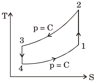
Ts diagram for air. 8.9.2019 · The air is compressed practically at a constant temperature T3 from V3 to V4. It means that the temperature T4 ( at point 4) is equal to the temperature T3 . This isothermal compression is represented by the curve 3-4 on P-V and T-s diagram. Description. A PV diagram plots the change in pressure P with respect to volume V for some process or processes. Typically in thermodynamics, the set of processes forms a cycle, so that upon completion of the cycle there has been no net change in state of the system; i.e. the device returns to the starting pressure and volume. On a p-V diagram, lines of constant temperature curve from the upper left to the lower right. A process performed at constant temperature is called an isothermal process. During an adiabatic process no heat is transferred to the gas, but the temperature, pressure... When air is taken from the compressor and used to cool the turbine it has an adverse effect on the amount of fuel required to give the required thrust. The TS diagram shown on the RHS is for a single spool turbojet, where a single drive shaft connects the turbine unit with the compressor unit.
V. the AIR flow diagram. VI. Maximum power transmitted through pipes. Entropy-temperature and transmission diagrams for AIR. 2. Acknowledgment.-The original entropy-temperature diagram for air, Fig. 1, was designed by the writer several years ago. Nov 22, 2021 · Using PEX for compressed air is also said, in some cases, to allow tiny amounts of air to leak through the plastic itself which is of course not by any means ideal in compressed air systems. There are very few (if any) PEX pipes that are stated as actually being sufficient to use with compressed air because most don’t specify. AIR-GROUND COMMUNICATION — Two-way com-munication between aircraft and stations or locations on the surface of the earth. AIR-GROUND CONTROL RADIO STATION — An aeronautical telecommunication station having primary responsibility for handling communications pertaining to the... same body of air for a process at a higher value of the pressure. For an ideal gas, nd the equation ofreversible isochors and isobars on a TS diagram.
Diagrams. Air, Gas, Temperature Entropy, T-s, Diagram, Chart. Temperature, Pressure, Specific Volume, Specific Internal Energy, Specific Enthalpy, Specific Entropy, Specific Exergy, Exergy Ratio. Density, Isobaric Specific Heat, Isochoric Specific Heat, Ratio of Specific Heat, Velocity of Sound. Usually, the electrical wiring diagram of any HVAC equipment can be acquired from the manufacturer of this equipment who provides the electrical wiring diagram in the user's manual In the next Article, I will explain Electrical Wiring Diagrams for different Air-Conditioning Systems Types and Equipment. TS Diagram of Air - Free download as PDF File (.pdf), Text File (.txt) or read online for free. diagram. TS Diagram of Air. Uploaded by. Allen Castor. Piping and Instrumentation Diagram—Air-Cooled. TS32 USER MANUAL SECTION 2 After the air/fluid mixture is discharged from the down. When the compressor is operating, the fluid stop valve is held open by air pressure from the compressor unit, the fluid is separated from the air. compressor...
Solved 4. Use the temperature entropy diagram provided to ...
SYSTEM DIAGRAM. Air Conditioning Amplifier. Combination Meter ECU. Ground for air inlet damper position sensor Ground for air outlet damper position sensor Ground for air mix damper position sensor Power supply for AC. 2. Check AIR conditioning amplifier (ts voltage).
Refrigeration and Heat Pump Systems - ppt video online download
18.1.2022 · Phylum Platyhelminthes are a phylum of relatively simple bilaterian, unsegmented, soft-bodied invertebrates that belongs to kingdom Animalia. This phylum contains 13,000 species and include many free-living and parasitic life forms. They are acoelomates (have no body cavity), and have no specialized circulatory and respiratory organs.
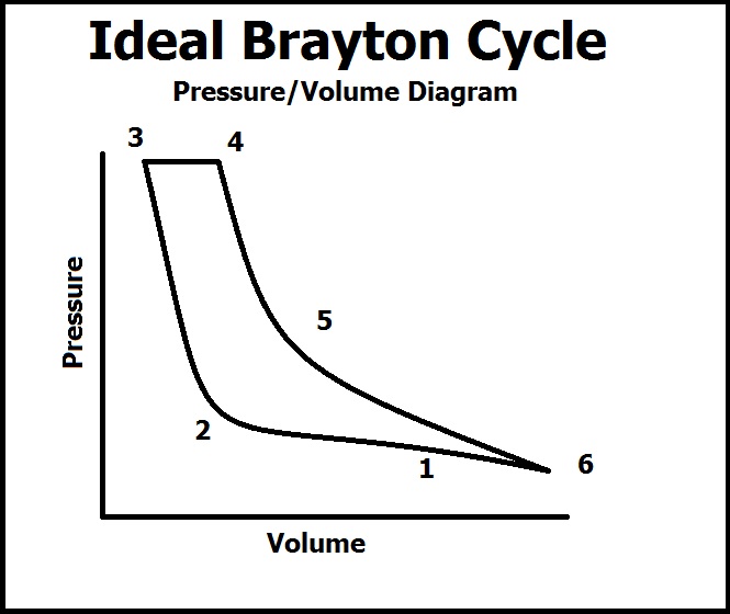
P-V and T-S Diagrams
2-5 Temperature-entropy diagram for air. Citation preview. Thermodynamic properties. Fig. 2-5 Temperature-entropy diagram for air. [Landsbaum, Dadds, Stevens, et al., Am. Inst.
Solved 1. Figure 1 shows the P-V and T-s diagrams for an ...
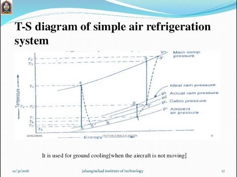
for understanding the block diagram of boot strap cooling system please watch my part 2 vedio. which shown at the end of this ... In this video,I have explained Simple Air Craft Refrigeration System od simple air refrigeration system with schematic, T-S ...

Dry Air - KCE - English
14. Carnot cycle TS diagram. As you know, thermodynamics is the branch of science which deals with the study of the conversion of heat energy into other forms of energy and gives information about this conversion quantitatively. TS diagram for a reversible Carnot cycle.
Brayton Cycle - Chemistry LibreTexts
More than 40+ schematics diagrams, PCB diagrams and service manuals for such Apple iPhones and iPads, as: iPhone XS, iPhone X, iPhone 8, iPhone 7, iPhone 6, iPhone 5, iPhone 4, iPhone 3; iPad 3, iPad 2. iPad Air Schematics Diagrams PDF.
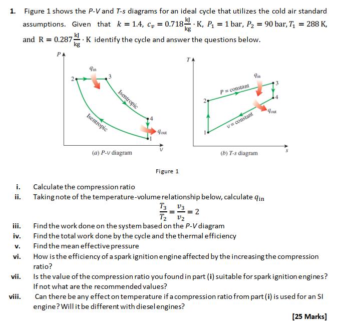
Solved 1. Figure 1 shows the P-V and T-s diagrams for an ...
A T-s diagram is the type of diagram most frequently used to analyze energy transfer system cycles. This is because the work done by or on the system and the heat added to or removed from the system can be visualized on the T-s diagram.

Ch8, Lesson C, Page 10 - Adiabatic Compresion: TS and HS Diagrams
Photosynthesis, the process by which green plants and certain other organisms transform light energy into chemical energy. During photosynthesis in green plants, light energy is captured and used to convert water, carbon dioxide, and minerals into oxygen and energy-rich organic compounds.
How to draw t-s diagram from p-v diagram? (with pictures ...
5 hours ago Ts = -26°C Ts = -47℃ log p-h diagram are therefore a direct measure for the energy flows exchanged. The distance 4 - 1 corresponds to the cooling capacity and is the net capacity of the refrigeration system. Stihl TS 800 Z Disc Cutter (TS 800 Z) Parts Diagram, Air.
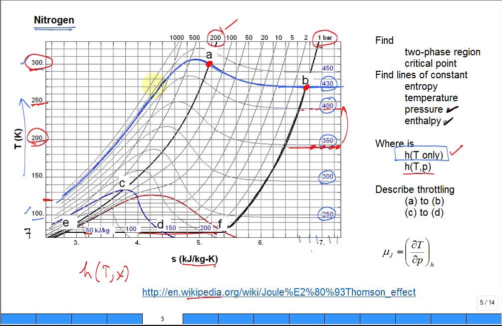
Explain Joule Thomson effect with Nitrogen TS diagram
ƒ Heat of Normal-to-Para conversion ƒ TS diagram for a pure substance ƒ Milestones in hydrogen liquefaction ƒ Liquid hydrogen production in the last 40 years ƒ Hydrogen liquefaction plants in North America ƒ Economics of liquefaction ƒ Four things that can be done to a gas ƒ Gas Liquefaction...

Air Standard Cycle - Lessons - Blendspace
Инструкция Apelson Air 101-600 Blanca. Портативная навигационная система. Инструкция Naviangel TS-140.

Regenerative Air Cooling System
Rocket propulsion is the force used by the rocket to take off. The principle used here is based on Newton’s third law of motion. To understand what is rocket propulsion diagram and its types along with an example, click here.

The T-s diagram of air-standard Otto cycle | Download ...
28.11.2021 · P-v and T-s Diagram of Diesel Cycle. Let the engine cylinder carry m kg of air at point 1. at this point let P1 and T1 and V1 be the pressure, temperature and volume of the air. Following are 4 stages of an ideal diesel cycle.
Dry Air - KCE - English
An air standard Otto cycle model is shown in Figure 1. The compression process is an isentropic process 1-2; the heat addition is an isohoric process 2-3 Faculty of Technical Sciences, Trg Dositeja Obradovića 6, 21000 Novi Sad, Serbia E-mail: jovan_d@uns.ac.rs. Figure 1. TS diagram for the air...

Ch10, Lesson E, Page 5 - TS Diagram for the Regenerative Cycle
Brayton Cycle - Ts diagram. Isentropic compression - ambient air is drawn into the compressor, pressurized (1 → 2). The work required for the compressor is given by WC = H2 - H1. Isobaric heat addition - the compressed air then runs through a combustion chamber, burning fuel, and air or...

Chapter 10a: a) Air - Water Vapor Mixtures (updated 5/10/10)
draw the Ts diagram for the air standard otto cycle. if we use an air standard otto cycle to model an internal combustion engine, what models the compression sstroke and what models the expansion stroke.
CHAPTER 1 - INTRODUCTION
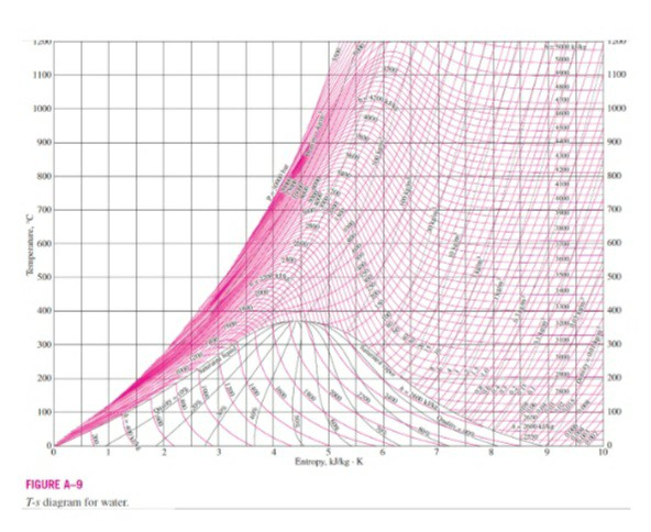
Ts diagram of water. TS diagram of waterПодробнее. Making sense of temperature-entropy diagramsПодробнее. 2.1. The T-s Diagram - Part 1Подробнее. Temperature Entropy DiagramПодробнее. Intuition For Reading PV & Ts DiagramsПодробнее.
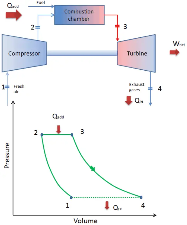
Brayton Cycle - pV - Ts Diagram
28.1.2022 · Forest Ecosystem: We come across many wild animals, birds, wild snakes, insects, etc., in the zoo.But, forests are the natural homes to many wildlife, birds, insects, flowering plants, etc. It is a piece of land with many trees, herbs, shrubs, etc. Forest ecosystems contribute much to the present world by producing fresh air, wood, medicinal by-products, etc.

Two-Stage and Multi-Stage Air Compressors - Bright Hub ...
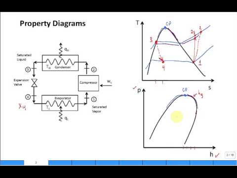
Actually other diagrams like p-h diagrams are also used in Refrigeration cycles. I think, and may be true, that the coordinates which are selected to represent the thermodynamic processes or cycles should carry a direct information which is of int...
Vapor-Compression Refrigeration
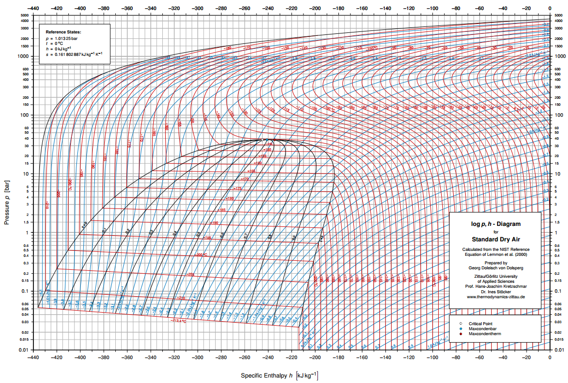
Calculation of thermodynamic state variables of air. lower limit for calculation: -150 C, 1 bar upper limit: 1000 C, 1000 bar. Calculation of Air : if you found an error, please mail to: wischnewski@mpib-berlin.mpg.de. No garanty for correctness.

Ideal Rankine Cycle
Air Rage (A) The first recorded case of an airline passenger turning seriously violent during a flight, a phenomenon now widely known as “air rage”, happened in 1947 on a flight from Havana to Miami. A drunk man assaulted another passenger and bit a flight attendant. However, the man escaped punishment because it was not then clear under whose legal control a crime …

Gas Power Cycles - Mech Engineering: Thermodynamics - UCL Wiki
Here we are going to study through pv and ts diagram in practical. Process 1-2: Reversible Adiabatic Compression Process: The cylinder contains full of air which is entered through the inlet port as we studied above. Here P1, V1, and T1 are the corresponding Pressure, Volume, and Temperature.

File:PV and TS diagram compressor.JPG - Wikimedia Commons
Stihl TS 400 Disc Cutter (TS400) Parts Diagram Select a page from the Stihl TS 400 Disc Cutter diagram to view the parts list and exploded view diagram.

August | 2013 | A Field Perspective on Engineering
TS 550 NV Floor spring for single leaf single and double-action doors of up to 1400 mm leaf width with adjustable closing force EN 3-6 and with hold-open function that can be switched on and off Closing force with variable adjustment EN3-6

Air T-s Diagram
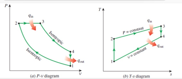
A PV diagram of the air standard Otto cycle is shown in Figure 2. The constant-volume process is thermodynamically efficient and, in principle, a feasible cycle. In contrast to the Carnot process, it avoids isothermal expansion and compression and the unrealistically high pressure ratio.
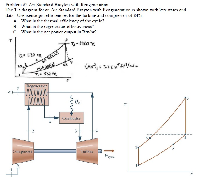
Solved Problem #2 Air Standard Brayton with Rengeneration ...
PH and TS Diagrams for Vapour Compression Refrigeration Cycle | VCR Cycle PV and TS In this video I have discussed about how to draw Ph,Ts, and Pv diagram for basic refrigeration cycle In this video he has explained the concept of Bell Coleman air refrigeration cycle with PV and TS diagrams.

Gas Power Cycles - Mech Engineering: Thermodynamics - UCL Wiki
R134a is being used in an air conditioning unit, steam tables for -5hf 0hf and -5sf 0sf written below in exrapolation. Related Threads on Thermofluids Air Conditioning Unit TS diagram.
The thermodynamic cycle shown in figure (Ts diagram) indicates
The Brayton or the Joule cycle is commonly used to analyze the gas turbine systems and the figure 2 shows a Temperature-Entropy (TS) diagram representation of an ideal Brayton cycle. In figure 2, from point 1 to point 2 the air is isentropically compressed and the heat is supplied at constant pressure...
File:Brayton cycle t-s and p-v diagram.gif - ccitonlinewiki
Cycle Name Process PV daigram TS diagram

Energy Analysis Software

Working of Reciprocating Air compressor - GeeksGod

Katalog - LD DIDACTIC

Jet Engine Ts Diagram | Jet engine, Engineering, Diagram

The air-standard diesel cycle is shown on p-V and T-s ...
How to draw T-S diagram for simple air cooling cycle (HINDI)

What do you mean by 'Perfect Intercolling' ? Explain with the ...

Air cycle combined heating and cooling for the food industry ...

Actual PV Diagrams Of 4 stroke And 2 stroke Marine Diesel Engines
Comments
Post a Comment