39 physical block diagram
Block Diagram , Computer , Networking , Technology. Hey, in this article I have given a very simple block diagram of IoT (Internet of Things) which will help you to understand the IoT architecture easily. IoT is an electronic ecosystem that connects electronic devices with the internet and provides their control and working status to the user ... A block diagram is a specialized flowchart used in engineering to visualize a system at a high level. SmartDraw helps you make block diagrams easily with built-in automation and block diagram templates. As you add shapes, they will connect and remain connected even if you need to move or delete items.
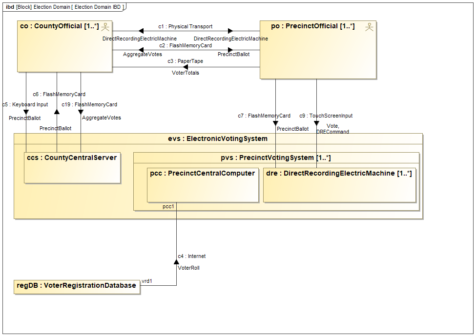
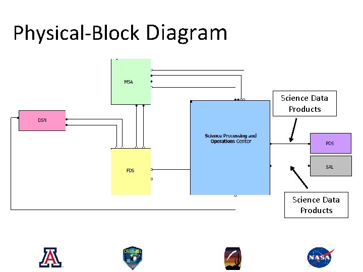
Physical Block Diagram (System Interconnection) June 2019 INCOSE -SD MBSE Tutorial. 14. AND OA.1.1.1.1 Produce FDS OA.1.1.1.2 Request Training (via Request Field Services) AND ... Block Definition Diagram • Internal Block Diagram Use Case Diagram • Activity Diagram Sequence Diagrams • State Machine Diagram Parametric
Physical block diagram
Block Diagram Components¶. So far, the focus of this chapter has been on acausal modeling. But Modelica also supports causal formalisms. The main reason for the emphasis on acausal modeling is that it lends itself very well to the modeling of physical systems. Embedded USB2 (eUSB2) Physical Layer Supplement to the USB Revision 2.0 Specification . Revision 1.1 Physical architecture descriptions use modeling techniques to create and represent physical architectures. Some common physical models include structural blocks, mass, layout and other models. Modeling techniques may be: Physical block diagrams (PBD) SysML block definition diagrams (BDD) Internal block diagrams (IBD) (OMG 2010)
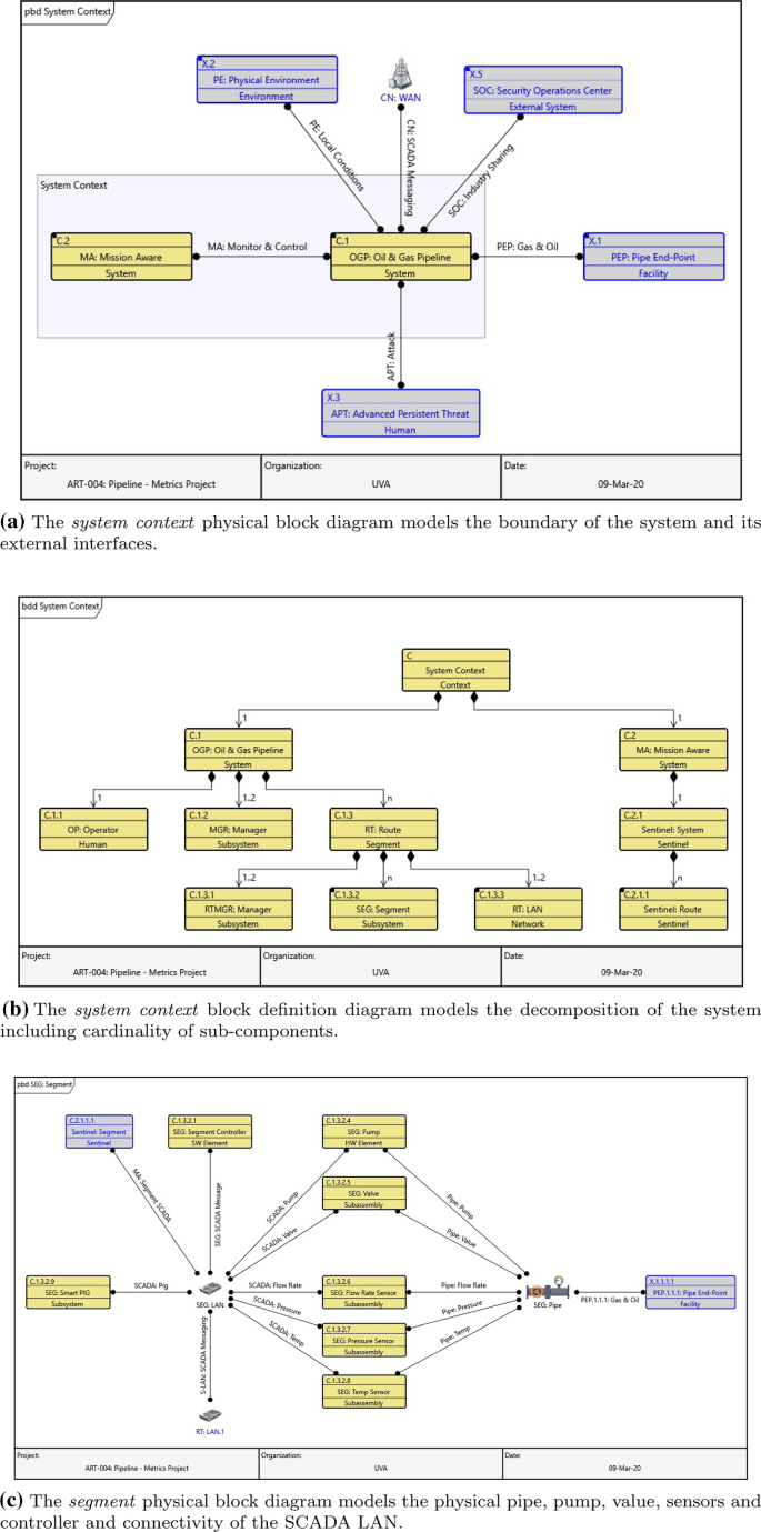
Physical block diagram. Guide to Construction of a Block Diagram . for Physical Medicine and Rehabilitation Residency Programs . Review Committee for Physical Medicine and Rehabilitation. A block diagram is a representation of the rotation schedule for a resident in a given post-graduate year. It offers information on the type, location, length, and variety of ... The physical block diagram is a traditional systems engineering block-and-line diagram representing the physical links that connect components within a system or system segment. Part of the physical architecture representation set, the physical block diagram is the more detailed view of the architecture composition. Asset Diagram. Last modified on July 21st, 2020. The 'Asset Diagram' is traditionally known as a block diagram or a physical block diagram. This diagram conforms to the LML Specification 1.1 definition of an 'Asset Diagram', which requires a diagram representation of the physical components of a system model. YouTube. SPEC Innovations. The physical block diagram can then be used to create the device floor plan. In many cases the physical block diagram results in a change to the logical partitioning of the device, converting it into a design which is more robust and implementable. A partition of the logic which is suitable for the physical constraints of the device can reduce the device area, and top level routing congestion. It can also significantly reduce the effort of timing closure and ultimately, the development ...
existence of dozens of block diagram algebra-related rules, hence it greatly helps the simpli-fication of block diagrams and makes teaching the simplification of block diagrams much easier. 7. The standard text recommended in the course, in addition to author's notes: K. Ogata, Modern Control Engineering, 3rd edition, Prentice-Hall, New ... Download scientific diagram | Physical block diagram of the Smart Service from publication: Robotic architecture based on electronic business models - from physics components to smart services ... of the elements, their interfaces, their logical and physical layout and the analysis of the design to determine expected performance". It is not a detailed design - that is performed by the subsystem design teams and is not a SE function. It begins www.nasa.gov as a hierarchy of major subsystems on a block diagram (e.g., an The physical block diagram is a traditional systems engineering block-and-line diagram representing the physical links that connect components within a system or system segment. If you are using a legacy schema (pre v90), CORE displays implied and "rolled up" connections based upon lower-level model details as well (this was discontinued in CORE 9 in favor of decomposable links).
System Block Diagrams ("System block diagram" is the the more hardware-oriented term which emphasizes functionalities and intercommunications. For software engineering, some will call this sort of diagram a "software block diagram" or simply a "block diagram".) ... Delineations of various boundaries in the system, both physical,e.g. in hardware ... NB-IoT supports the operation with either one or two antenna ports, AP0 and AP1. For the latter case, Space Frequency Block Coding (SFBC) is applied. Once selected, the same transmission scheme applies to NPBCH, NPDCCH, and NPDSCH. Like in LTE, each cell has an assigned physical cell ID (PCI), the Narrowband physical cell ID (NCellID). For example, Temperature data generated by a Temperature Sensor in Home or other place, when processed can help in determining temperature and take action according to users. Above picture, shows a generic block diagram of IoT device. It may consist of several interfaces for connections to other devices. A block diagram is a diagram of a system in which the principal parts or functions are represented by blocks connected by lines that show the relationships of the blocks. They are heavily used in engineering in hardware design, electronic design, software design, and process flow diagrams.. Block diagrams are typically used for higher level, less detailed descriptions that are intended to ...
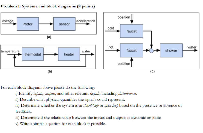
Solved Problem 1: Systems and block diagrams (9 points ...
15 kHz. Time-frequency resources are allocated in units of physical resource blocks (PRBs) comprised of 12 subcarriers in frequency and 1frame in time sub- . The detailed downlink OFDM modulation parameters may be in [1]. The block diagram of found an OFDM transceiver is shown in Figure 2.
Featured Visio templates and diagrams
So, any IOT system is built from the physical world, virtual world and a communication network. These three are broadly the basic blocks of an IOT system. So, an IOT system can be precisely represented by the following block diagram -

New Switch Families Aim to Break Down Complicated Network ...
Physical block diagram Modelica is a non-proprietary, object-oriented, multi-domain modelling language for component-oriented modelling of complex systems [4]. Users can represent physical systems using simple blocks which already represent the mathematical model , this way the blocks can be directly connected and their propertires can be ...

Easily Understand IOT Block Diagram and Architecture - ETechnoG
Download scientific diagram | Physical block diagram. from publication: 500-MHz pipelined burst SRAM with improved SER immunity | This paper describes a 0.25-μm, 64 K×36 bit pipelined burst SRAM ...

Physical block diagram. | Download Scientific Diagram
The physical block diagram includes implied connections between internal components and with external components based upon the connects thru relationships. The level 0 diagram simplifies the representation and focuses solely upon the explicit connections defined by the connects to relationships. However, both use the same fundamental notation. For that reason, the diagram types share a common set of preferences.

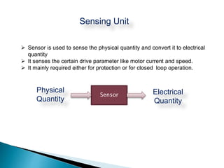
BLOCK DIAGRAM OF GENERALIZED MEASUREMENT SYSTEM Components of
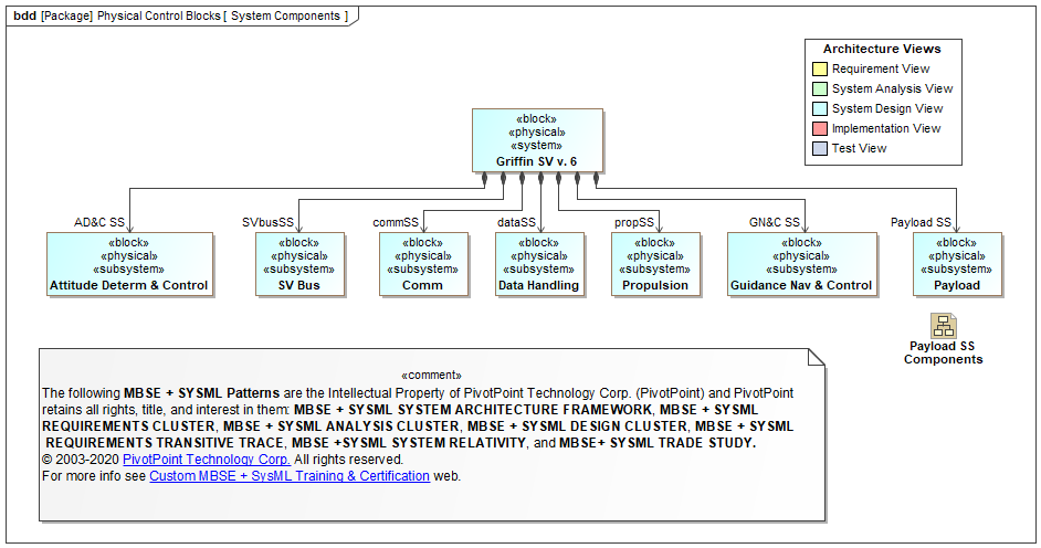
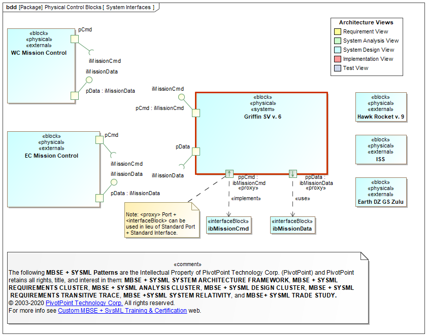
The physical block diagram is classically a higher level physical "wiring" diagram than its SysML flow IBD counterpart. This makes it a good candidate for using graphic images in place of geometric nodes to increase the communication value. Using a diagram shape in conjunction on block diagrams is a good way to graphically indicate clusters.
Functional Architecture. What Is It and Why Every System ...
Building upon what you learned in the Getting Started Collection, the Skill Building Collection will guide you through the next steps of efficiency and effic...

Wimax Physical layer | OFDM Physical layer of WiMAX
difference between physical diagram and block diagram. Developing Logical Data Flow Diagrams. Some common physical models include structural blocks, mass, layout and other models. It is used to design new systems or to describe and improve existing ones. Basic Elements of Block Diagram.

Physical Design of IoT, Generic Block Diagram of IoT devices
block (used on first-and lower-level function diagrams only) Ref 9.2, Provide guidance Functional description Function number Summing gate Parallel functions 9.2.1 3.5 Ref and 1.1.2 Ref or and or or 9.2.2 9.2.3 9.2.4 Ref. 11.3.1 Alternate functions See Detail Diagram Sys Malf. Leader note See Detail Diagram No go flow G See Detail Diagram Go ...
What is Block Diagram – Everything You Need to Know ...
Physical Block (and Level 0 Physical Block) Diagram User Preferences. The physical block diagram preferences allow you to determine the initial interaction settings for physical block and level 0 physical block diagrams (the presence of the palette and table plus the diagram scale) and whether these diagrams appear on CORE toolbars and menus.
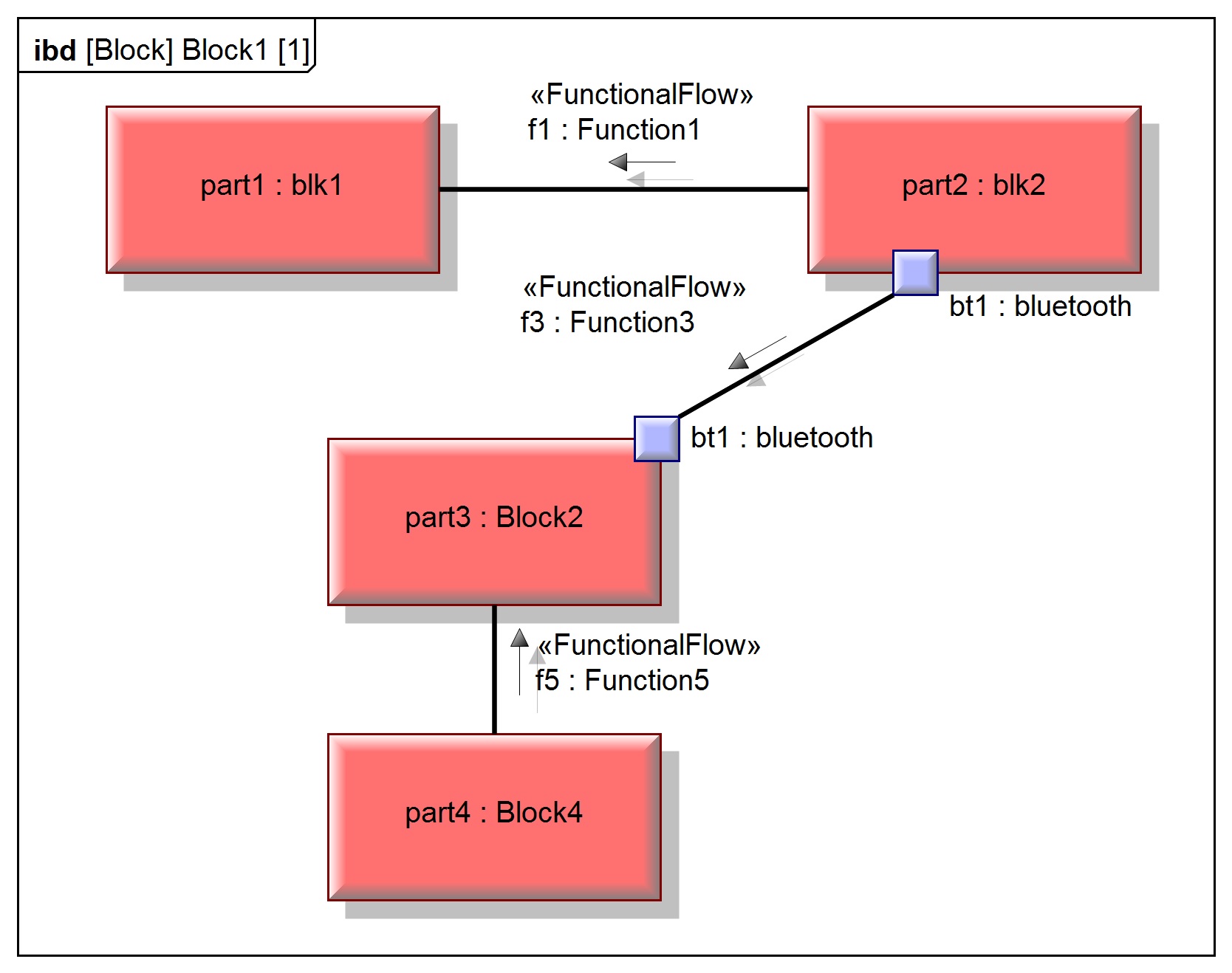
SysML FAQ: What is an Internal Block Diagram (IBD)?
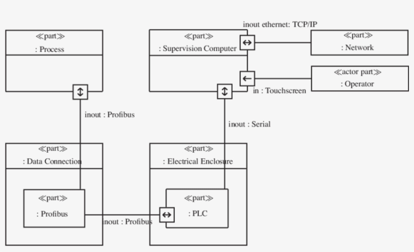
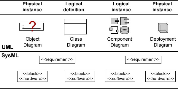
A block visualizes a system building block and describes logical and physical system components. An open block shows additional properties like parts or ...
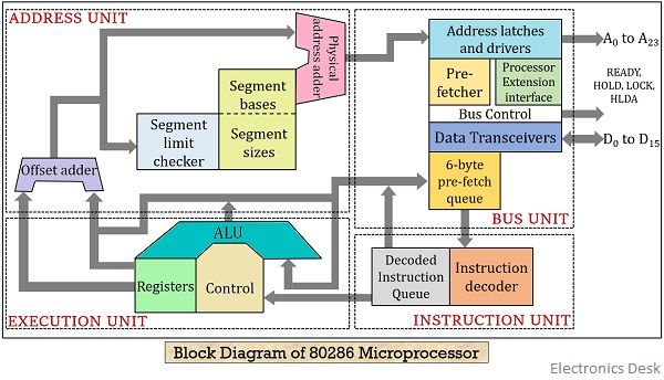
What is 80286 Microprocessor? Modes of Operation and ...
Physical architecture descriptions use modeling techniques to create and represent physical architectures. Some common physical models include structural blocks, mass, layout and other models. Modeling techniques may be: Physical block diagrams (PBD) SysML block definition diagrams (BDD) Internal block diagrams (IBD) (OMG 2010)
A Sysml Internal Block Diagram In Papyrus - Sysml Internal ...
Embedded USB2 (eUSB2) Physical Layer Supplement to the USB Revision 2.0 Specification . Revision 1.1

VDI Block Diagram | NCS Technologies, Inc.
Block Diagram Components¶. So far, the focus of this chapter has been on acausal modeling. But Modelica also supports causal formalisms. The main reason for the emphasis on acausal modeling is that it lends itself very well to the modeling of physical systems.

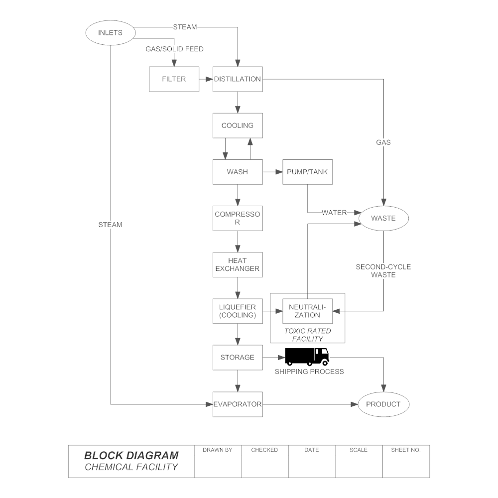
Block Flow Diagram - an overview | ScienceDirect Topics
An ontological metamodel for cyber-physical system safety ...
internal-block-diagram-magicdraw-sysml - Intercax
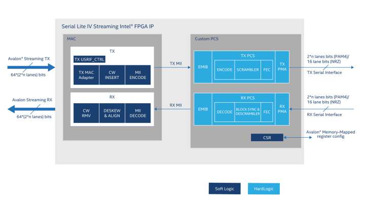
Serial Lite IV Intel® FPGA IP Core

Physical access management block diagram - Electronic Products

Block Diagram of SCADA System, SCADA Architecture Diagram ...

Block Hierarchy - an overview | ScienceDirect Topics
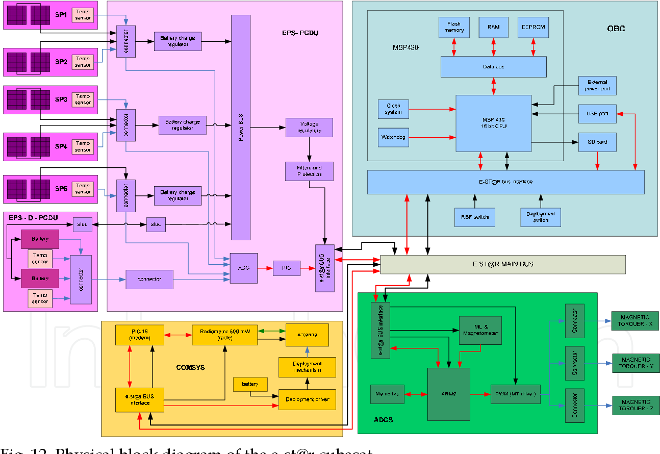
Figure 12 from Functional Analysis in Systems Engineering ...
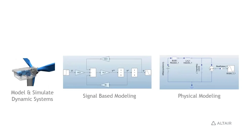
Altair Activate 1D Block Diagram Modeling
1.general block diagram
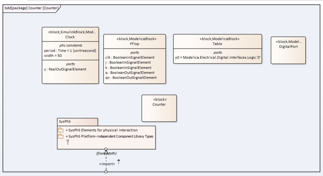
SysPhS Block Definition Diagram - Flip-Flop Binary Counter ...

85 Physical - N 20PA Pulse Oximeter - Raynet Repair Services
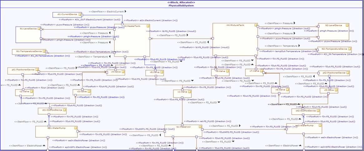
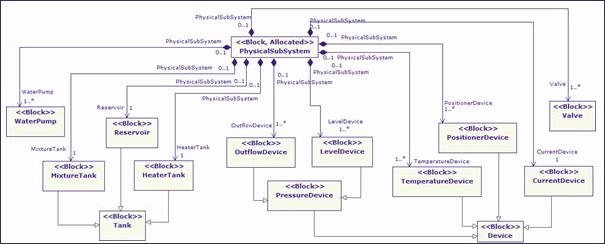
Modeling the physical subsystem
A personal view of SysML Block Diagrams – Caminao's Ways
UTILIZING MODELBASED SYSTEMS ENGINEERING TO MODEL DATA PROCESSING
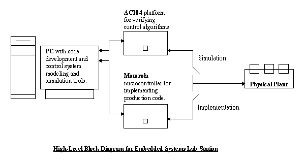
System Block Diagram

File:20200118 Global warming and climate change - vertical ...
SysML FAQ: What is a Block Definition Diagram (BDD)?

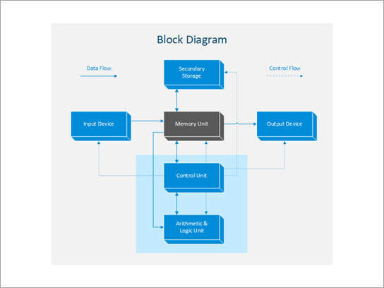
define block diagram of computer with diagram ​ - Brainly.in

FMEA Corner: Making the FMEA Scope Visible
Physical Research Laboratory

Physical Block Diagram
Modeling the physical subsystem

ML350G COMPUTER SERVER Block Diagram OPTIMA s Hewlett-Packard ...

FullChip physical block diagram | RTLery
Comments
Post a Comment