39 hvac unit diagram
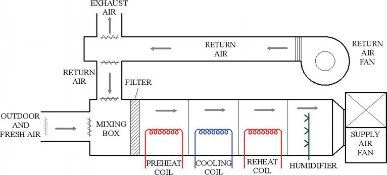
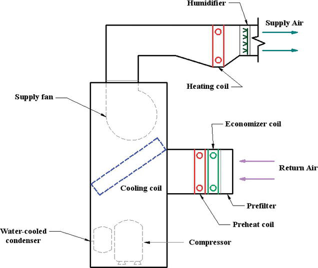
Starting at point A on the diagram above, return air passes through the filters on the system and is drawn into the supply fan. The air is then pushed into the dual duct section of the unit. It will now separate into two ducts, one that will handle the heating functions and one that will handle the cooling functions: Specifications subject to change without notice. 421 03 5400 01 1/22/2018 WIRING DIAGRAM MANUAL Split System Air Conditioner N4A3, R4A3, WCA3**4, NXA4, R4A4, WCA4**4 N4A5, R4A5, WCA5**4, N4A6, NXA6
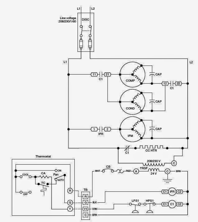
Oct 27, 2021 · Hvac wiring diagrams 101. Warning death personal injury and or property damage hazard failure to carefully read and follow this warning. The first and most common is the ladder diagram so called because it looks like the symbols that are used to represent the components in the system have been placed on the rungs of a ladder.

Hvac unit diagram
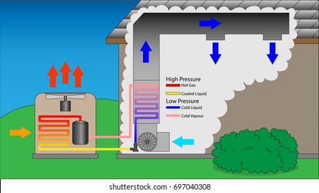
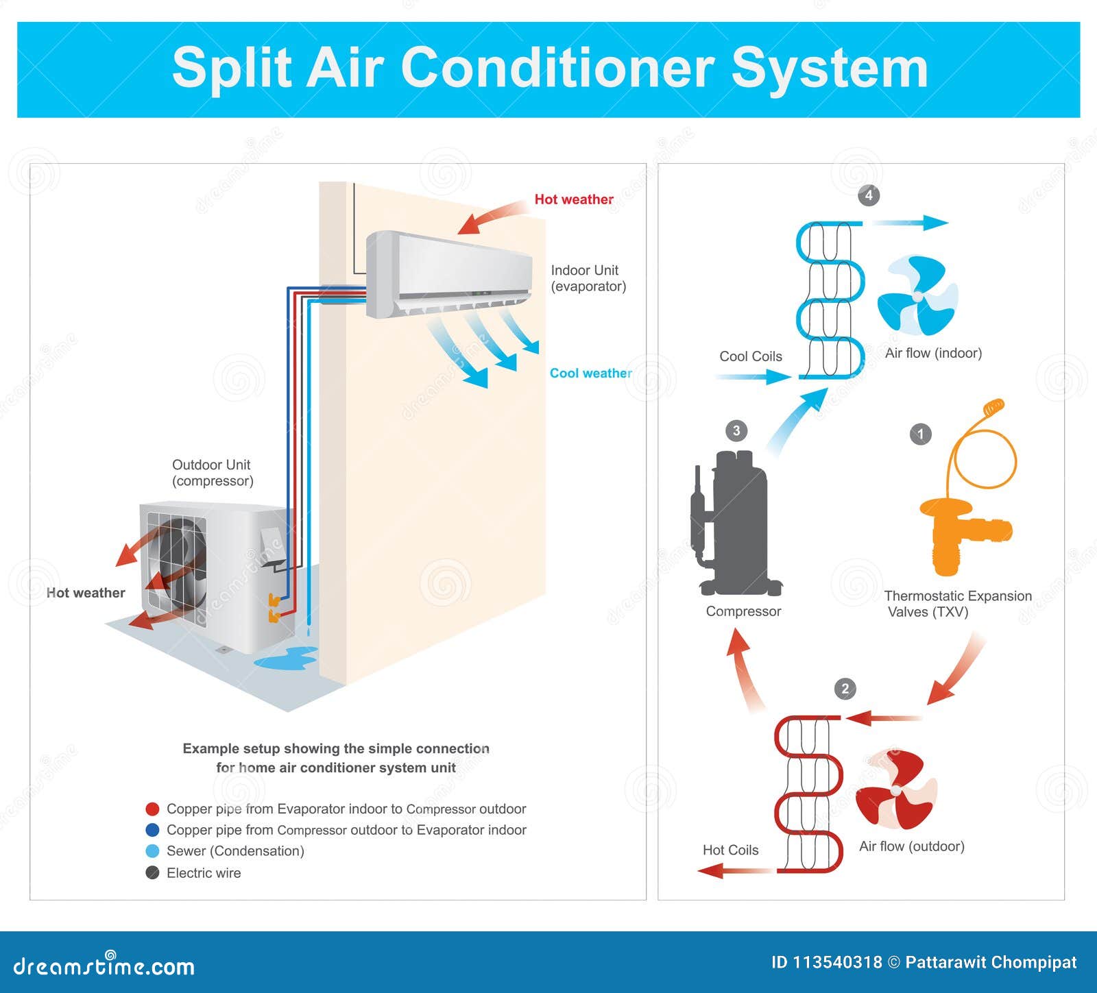
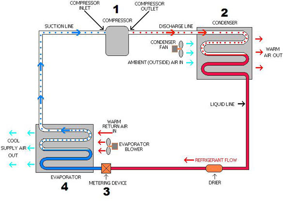
Cold refrigerant arrives at the indoor unit of an air conditioner. The heat energy from a room always absorbed by the cold refrigerant and carry away from the room. Thus, cooling the room. Refrigeration Cycle Explained with Diagram. An air conditioner operates using the refrigeration cycle. There are many types of refrigeration cycles. Aug 12, 2020 · HVAC is the system in your home responsible for Heating, Ventilating, and Air Conditioning. The term HVAC refers to any unit that can heat or cool. So this means everything from the big units outside of factories to the smaller unit outside your home all qualify as HVAC systems. Good HVAC systems use the science of thermodynamics, heat transfer ... Bard HVAC - Delivering high performance heating and cooling products all over the world
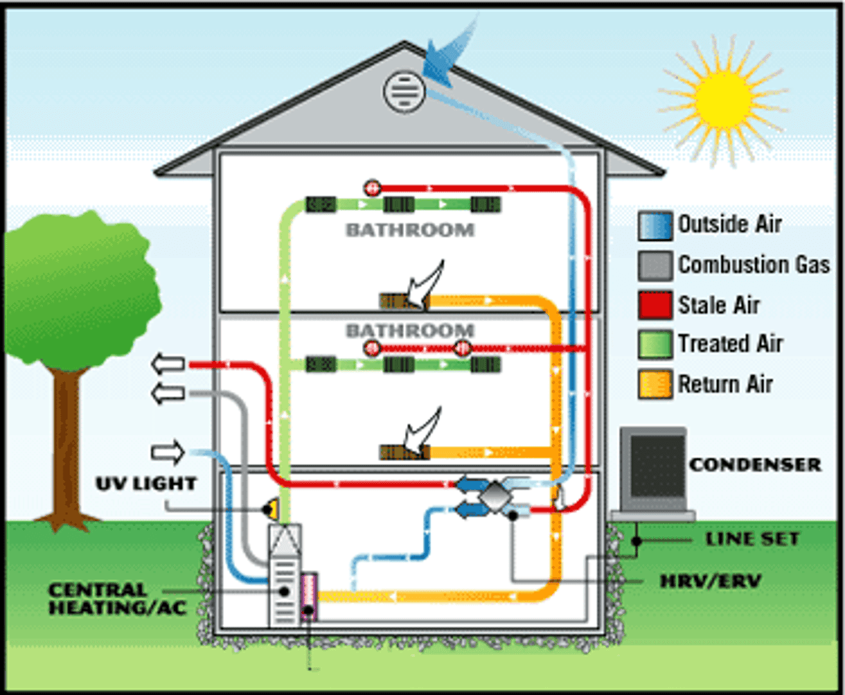
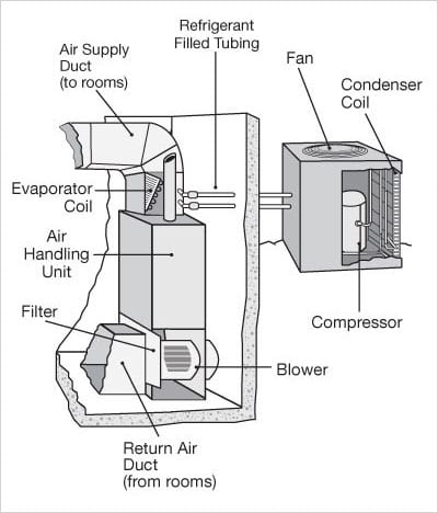
Hvac unit diagram. HVAC System Components Diagram. In the following diagram, you can find some major components that concern pretty much all HVAC systems. There are, of course, differences between different HVAC system configurations, but the core concept and HVAC components are basically common among all of them. This Hvac For Beginners section begins here with a discussion about forced air duct systems, the basics, the how and why of duct sizing. Ductwork is simply an air delivery system. A delivery system for all forced air systems, furnace or air handler, heating or air conditioning, or both. This is the piece of your air conditioning system that most people never see. It's contained in a metal box called a plenum, and sits on top of your furnace. If you have a horizontal furnace in an attic, the evaporator coil will sit on one end of the furnace instead of on top. The 'inside unit' or 'indoor coil' are other common names ... The vector stencils library "HVAC equipment" contains 26 symbols of HVAC equipment. Use it for drawing HVAC system diagrams, heating, ventilation, air conditioning, refrigeration, automated building control and environmental control system layout floor plans in the ConceptDraw PRO diagramming and vector drawing software extended with the HVAC Plans solution from the Building Plans area of ...
Hvac Unit Diagram : Refrigerant Recovery Machine, Hose, and Tank Setup. This guide highlights four ac brands with the best reputation and will hopefully help you in your. Exceptional job growth is anticipated over the next decade for hvac technicians, sparked by commercial building construction. Check supply and return vents for obstructions. Control Diagrams and Symbols Symbols for HVAC system components Refer to ASHRAE Fundamentals Handbook 2005 Chp. 37, Abbreviations and Symbols Refer to other local standards or guidelines Usually specified in the contract drawings & documents Generic control diagrams Using generic symbols to describe and define the 4 - Learn about the variables that influence the cost of HVAC replacement. Here are the variables that you have to consider: Size of equipment: the price of a furnace and/or air conditioner varies with the size of the equipment. The size of the equipment is measured in BTUs (British Thermal Unit). Kind of equipment: Thermostat Wiring Diagrams for Heat Pumps - Heat Pump Thermostat Wire Diagrams. Heat pumps are different than air conditioners because a heat pump uses the process of refrigeration to heat and cool.While an air conditioner uses the process of refrigeration to only cool, the central air conditioner will usually be paired with a gas furnace, an electric furnace, or some other method of heating.
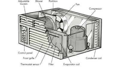
HVAC. Figure 1. The outdoor condensing portion of an air conditioning unit. The air conditioning unit is one portion of an HVAC system. HVAC is an acronym for heating, ventilating, and air conditioning. The term refers to a group of systems and machines used in buildings such as homes and buildings that regulate the indoor temperature and air ... The window air conditioner unit consists of the following components as shown in fig Refrigeration unit Evaporator/cooling coil, condenser, compressor, expansion device Air circulation fan. windows air conditioning diagram. Working. To keep track of wiring, HVAC technicians rely on circuit schematics or visual representations of wiring programs. There are three basic types of circuit schematics used in HVAC today. They are the Line Diagram, the Ladder Diagram, and the Installation Diagram. You can think of these circuit schematics as road maps. Nov 25, 2021 · Schematic Diagrams for HVAC Systems: What You Need to Know. November 25, 2021. If you know a little bit about home heating and cooling systems, you probably realize that they are pretty complicated little systems! Inside those compact units are electrical connections, fans, compressors, condensers, switches, coolants—the list goes on and on.
HVAC System Block Diagram | PDF | Cold | Civil Engineering
3- Types of Electrical Wiring Diagrams For Air Conditioning Systems. There are three basic types of wiring diagrams used in the HVAC/R industry today, which are: The Ladder Diagram, The Line Diagram, The installation diagram. 3.1 The Ladder Diagram.
What is HVAC System ? | HVAC system working Principle
HVAC Systems: Overview Michael J. Brandemuehl, Ph.D, P.E. University of Colorado Boulder, CO, USA Overview System Description Secondary HVAC Systems Air distribution Room diffusers and air terminals Duct Design Fan characteristics Air Handling Units Water distribution Cooling coils Pipes and pumps Primary HVAC Systems Electric chillers
Air Conditioning Basics For Beginners
HVAC. HVAC - Heating, Ventilation, Air-conditioning. Temperature. Humidity. Pressure. Ventilation. 68°F (20°C) and 75°F (25°C) 30%. relative humidity (RH) and 60% RH . A slightly positive pressure to reduce outside air infiltration. Rooms typically have several complete air changes per hour . Diagram of mechanical system on the blackboard

What are the types Of Air Conditioning | Basic Of Air ...
assume Units 1 and 2 are base-loaded, and Unit 3 has just cycled on. When the cycling portion of the load is satisfied, Unit 1 cycle off, and Units 2 and 3 become base loaded. When more capacity is needed, Unit 4 cycles on, and so on. Where are HVAC controls required? The HVAC control system is typically distributed across three areas:
Types of HVAC Systems | IntechOpen
How does an air conditioning system work? This expert article, along with diagrams and video, clearly explains how a central air conditioner cools a house by cycling refrigerant through its system and delivering chilled air through ductwork. Diagram of a central air-conditioning system of a house including a network of warm air and cold air ducts.

How do air conditioners work? - Explain that Stuff
HVAC - Heating, Ventilating, and Air Conditioning Block Diagram. Posted on November 13, 2013 by Electronic Products ... This allows designers to use a high-efficiency compressor motor in the outdoor unit of the air conditioner. Power Factor Correction (PFC) :
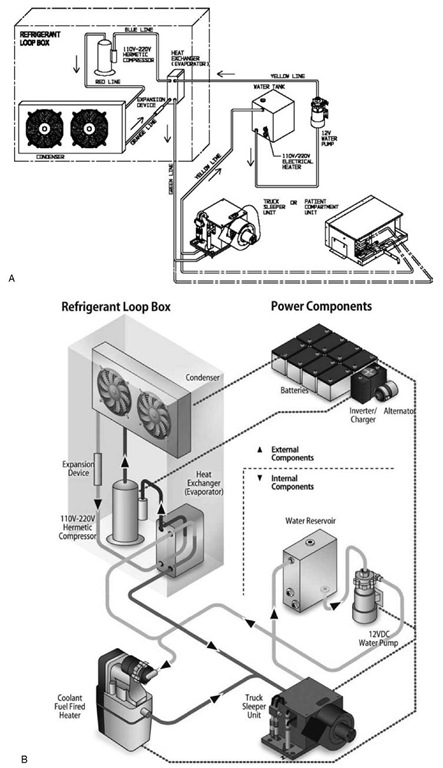
Mobile HVAC Systems: Fundamentals, Design, and Innovations ...
Before getting to know the Hvac Unit Diagram, would it be better to understand what HVAC itself is? Is an extension of Heating Ventilation and Air Conditioning. For simplicity, people usually refer to HVAC only.

The Schematic Diagram Of The Investigated Hvac System - Hvac ...
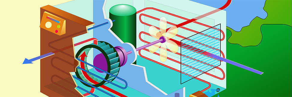
Jun 15, 2020 · HVAC System Parts and Diagram Image from 21celcius There are different parts for a HVAC system based on its application, but one can consider what occurs in a evaporative cooling system as a widely used case throughout the world and get a sense of what is generally happening in the system.

Apartment Diagram with Radiator Heating and Air Conditioning ...
Self-Contained Two-stage Air Conditioner with Single Stage Electric Heat 24 Volt+ Fan Only Operation Common Stage 1 Cooling Stage 2 Cooling Heat Some AC Systems will have a blue wire with a pink stripe in place of the yellow or Y wire. 19 This diagram is to be used as reference for the low voltage control wiring of your heating and AC system.

split wall piping diagram. | Refrigeration and air ...
Carrier air conditioning unit wiring diagram fresh ac unit wiring. The wiring from the disconnect to the outside condensing unit is almost always the same. Ac Wiring Diagram Of Window Airconditioner Ac Wiring Thermostat Wiring Wire Click on the image to enlarge and then save it to your computer by right clicking on the image. …

The HVAC system diagram from PEIDE-HVACAQUA.COM
We include immediate downloads of example installation & repair manuals and wiring diagrams for air conditioners, heat pumps, and heating equipment from a variety of manufacturers as well as contact information to obtain the exact manual or wiring diagram for your unit.

Split AC Indoor To Outdoor Wiring Diagram
Bard HVAC - Delivering high performance heating and cooling products all over the world

Split type air conditioner | Diagram , Working , Parts
Aug 12, 2020 · HVAC is the system in your home responsible for Heating, Ventilating, and Air Conditioning. The term HVAC refers to any unit that can heat or cool. So this means everything from the big units outside of factories to the smaller unit outside your home all qualify as HVAC systems. Good HVAC systems use the science of thermodynamics, heat transfer ...

How Do Air Conditioning Systems Work in a Car?
Cold refrigerant arrives at the indoor unit of an air conditioner. The heat energy from a room always absorbed by the cold refrigerant and carry away from the room. Thus, cooling the room. Refrigeration Cycle Explained with Diagram. An air conditioner operates using the refrigeration cycle. There are many types of refrigeration cycles.
Types of HVAC Systems | IntechOpen

Outside AC Unit Diagram | Schematic of water cooled air ...
Hvac Diagram Depicting Both Air Flow Stock Vector (Royalty ...
Schematic Diagrams for HVAC Systems - Modernize

Five Basic Components of an Effective Air Conditioning System

Voltas 5 Star HVAC AC System Diagram, For Industrial Use ...
How Do Air Conditioners Work?

Self-contained Basic Wire Diagram - Ocean Breeze Mfd. by ...

Sample HVAC System Diagram from Protecting Building Occupants

The car AC diagram, features are described here briefly ...
The Basics Of HVAC - Green Living Ideas
Split Air Conditioner System Stock Vector - Illustration of ...

Pin on Split AC

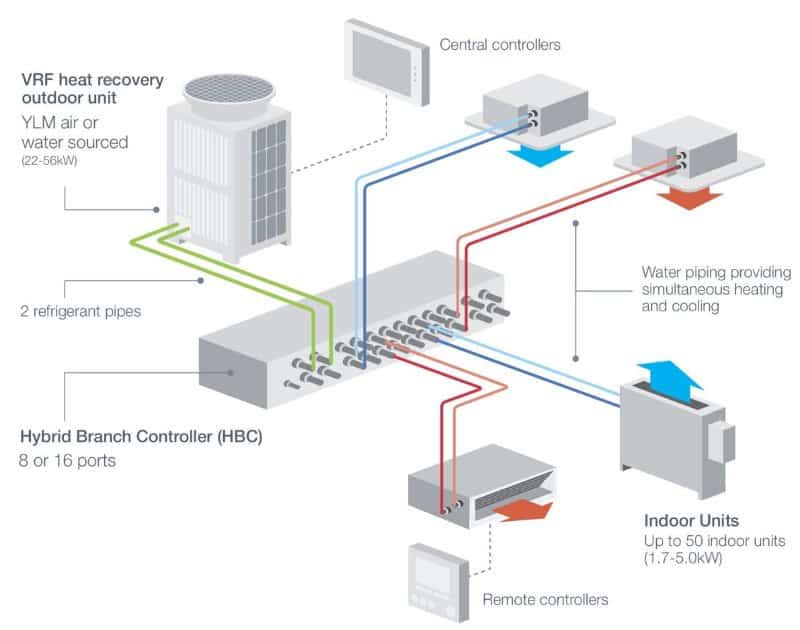
What is a VRF System? Variable Refrigerant Flow HVAC ...
Air conditioning system

Why It Is Important To Understand HVAC Block Diagrams(AC) -
Ultimate List of HVAC Terminology | AC Definitions ...
Why are HVAC systems the backbone of buildings? | Building ...
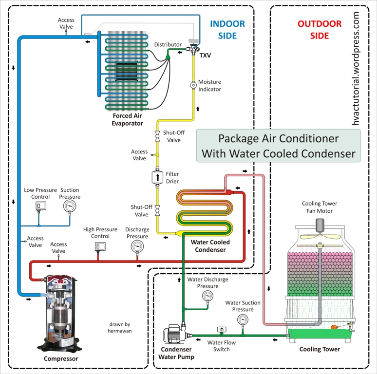
Package Air Conditioning System | Hermawan's Blog ...
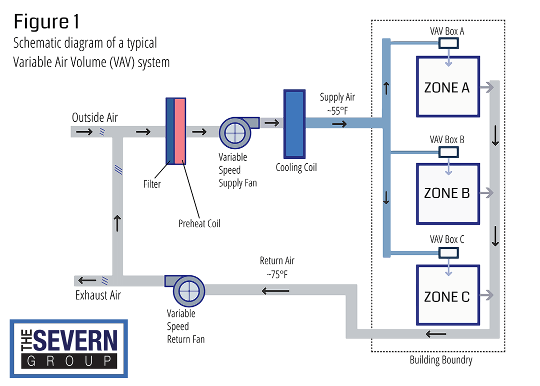
VAV vs VVT HVAC Systems - The Severn Group
How does air conditioning work? – Heating, Air Conditioning ...

What You Should Know About Your HVAC's Schematic Diagrams

What is Air Conditioning System? Diagram, Applications - ETechnoG

Marine Accommodation Air Conditioner Piping Diagram ...

View How A Home Hvac System Works Pics - Conseils d'ingénierie
Comments
Post a Comment