39 draw a ray diagram of the lens system you set up in c6
PDF Experiment 6 Optics: Focal Length of A Lens a) For convenience of discussion we assume that the light passes through the lens from left to right. Ray diagrams will follow this convention. (b) The focal point of a lens is found by allowing a bundle of mutually parallel rays to enter the lens (i.e., from an object infinitely far from the lens). The lens alters the direction of these rays, Concave Lens - Ray diagram, Images Formed - with Steps ... First, we draw a ray parallel to principal axis. So, it appears to pass through focus after reflection. We draw another ray which passes through Optical Center. So, the ray will go through without any deviation. Where both reflected rays meet is point A'. And the image formed is A'B'. This image is formed between F 1 and Optical Center (O)
39 ruger 10/22 diagram double kitchen sink plumbing diagram; draw a ray diagram of the lens system you set up in c6; draw the shear and moment diagram for the beam; dry cell battery diagram; dryer motor wiring diagram; dual xdm260 wiring diagram; duo therm wiring diagram; duraspark wiring diagram; dyson dc15 parts diagram; e maxx parts diagram; e30 fuse diagram; e30 ...

Draw a ray diagram of the lens system you set up in c6
Multiple lens systems (video) | Lenses | Khan Academy This is the second image that this lens system is going to create and so I'll just put di. Alright, so we do the math, alright 1 over negative 10 centimeters minus 1 over 15 centimeters equals 1 over di, you solve that on the left hand side. You flip it over, you're going end up getting the di is, once you do that inversion negative 6 centimeters. PDF Lab 2: LENSES, LENS SYSTEMS, and SIMPLE OPTICAL ... the image distance for the first lens and the separation between the two lenses. Be careful of the sign. 4. Consider again Problem 3, but for the case when d < (f 1 + f 2). Draw a ray diagram clearly indi-cating the rays from the object through the first lens to an image. Draw another diagram indicat- Concave Mirrors And Convex Mirrors - Image Formation, Ray ... Concave Mirror Ray Diagram lets us understand that, when an object is placed at infinity, a real image is formed at the focus. The size of the image is much smaller compared to that of the object. When an object is placed behind the center of curvature, a real image is formed between the center of curvature and focus.
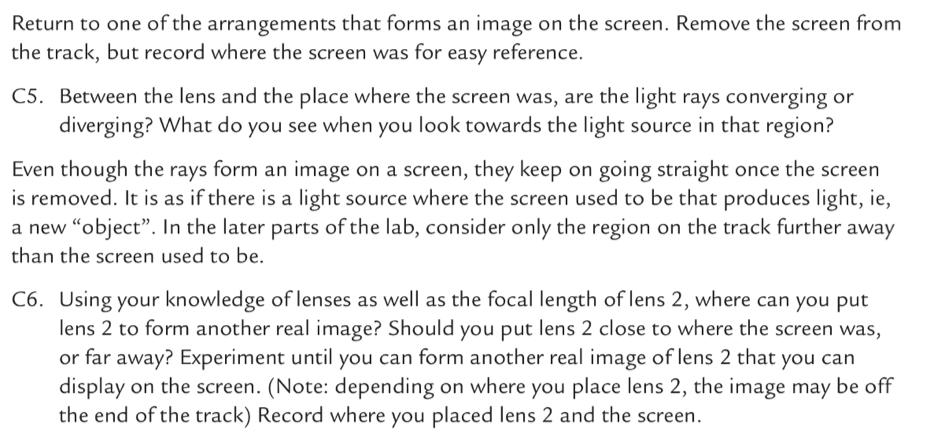
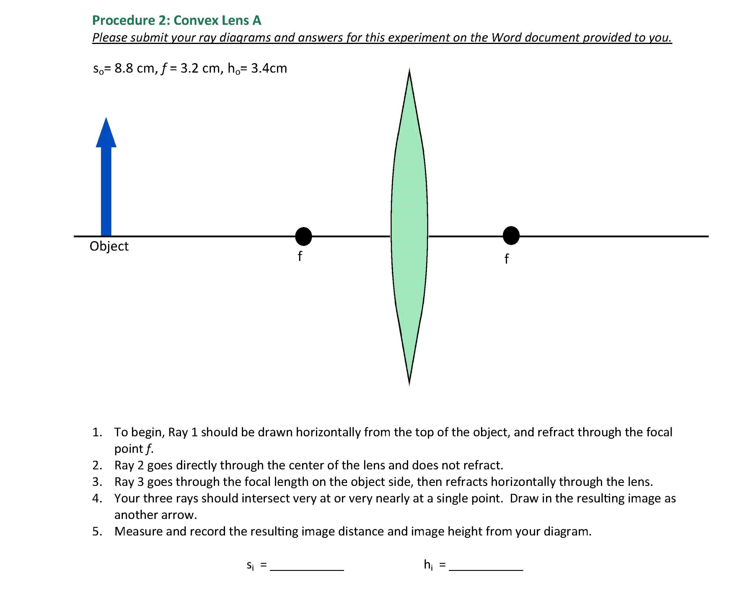
Draw a ray diagram of the lens system you set up in c6. Refracting Telescope Ray Diagram - schematron.org Jan 27, · When you look up a ray diagram for a telescope you get the following: From reading my book it seems clear that the objective lens forms and image on the focal plane. This then serves as an image for the eyepiece. Since the focal length of the eyepiece at the focal length of the objective lens you get a virtual image at infinity. Physics Tutorial: Ray Diagrams - Concave Mirrors The method is applied to the task of drawing a ray diagram for an object located beyond the center of curvature (C) of a concave mirror. Yet the same method works for drawing a ray diagram for any object location. 1. Pick a point on the top of the object and draw two incident rays traveling towards the mirror. PDF The Lens Equation - University of Plymouth For aconvex lens, we draw the ray diagram as follows: Draw a ray from the top of the object straight through the middle of the lens. Its direction is not changed. Draw a ray from the top of the object parallel to the principal axis. It is refracted by the lens to pass through the focal point. F From the diagram we see that the image in this ... Solved 7.In one to three sentences, describe the ... - Chegg 10.a.Draw a ray diagram of the lens system as it should look at the end of Step C6 (the set up for forming the image of areal image).Draw the ray diagram roughly to scale and label all lengths (based on the values given in the dataset.)b.
Ray Diagrams for Lenses - Georgia State University A ray through the center of the lens, which will be undeflected. (Actually, it will be jogged downward on the near side of the lens and back up on the exit side of the lens, but the resulting slight offset is neglected for thin lenses.) A ray through the principal focal point on the near side of the lens. Ray diagrams and images - Lenses - Edexcel - GCSE Physics ... A real image is an image that can be projected onto a screen. A virtual image appears to come from behind the lens. To draw a ray diagram: Draw a ray from the object to the lens that is parallel ... Solved Draw a ray diagram of the lens system as it should ... Question: Draw a ray diagram of the lens system as it should look at the end of Step C6 (the set up for forming the image of areal image).Draw the ray ...1 answer · Top answer: To form a real image using an image, the second lens must be placed before the image is formed. Thus, from the... Ray Diagrams - Physics Classroom Step-by-Step Method for Drawing Ray Diagrams. The method of drawing ray diagrams for double convex lens is described below. The description is applied to the task of drawing a ray diagram for an object located beyond the 2F point of a double convex lens. 1. Pick a point on the top of the object and draw three incident rays traveling towards the ...
Ray Optics Simulation - Home - GitHub Pages Ray Optics Simulation ... " mirror which obeys exactly the mirror equation (1/p + 1/q = 1/f). The focal length (in pixels) can be set directly. Beam Splitter. A mirror that transmits a percentage of incoming light. ... (Ideal lens) An ideal lens that obeys exactly the thin lens equation (1/p + 1/q = 1/f). The focal length (in pixels) can be set ... Concave Mirrors And Convex Mirrors - Image Formation, Ray ... Concave Mirror Ray Diagram lets us understand that, when an object is placed at infinity, a real image is formed at the focus. The size of the image is much smaller compared to that of the object. When an object is placed behind the center of curvature, a real image is formed between the center of curvature and focus. PDF Lab 2: LENSES, LENS SYSTEMS, and SIMPLE OPTICAL ... the image distance for the first lens and the separation between the two lenses. Be careful of the sign. 4. Consider again Problem 3, but for the case when d < (f 1 + f 2). Draw a ray diagram clearly indi-cating the rays from the object through the first lens to an image. Draw another diagram indicat- Multiple lens systems (video) | Lenses | Khan Academy This is the second image that this lens system is going to create and so I'll just put di. Alright, so we do the math, alright 1 over negative 10 centimeters minus 1 over 15 centimeters equals 1 over di, you solve that on the left hand side. You flip it over, you're going end up getting the di is, once you do that inversion negative 6 centimeters.
Drawing ray diagrams for a converging lens - The Fizzics ...
OSLO User Guide.pdf
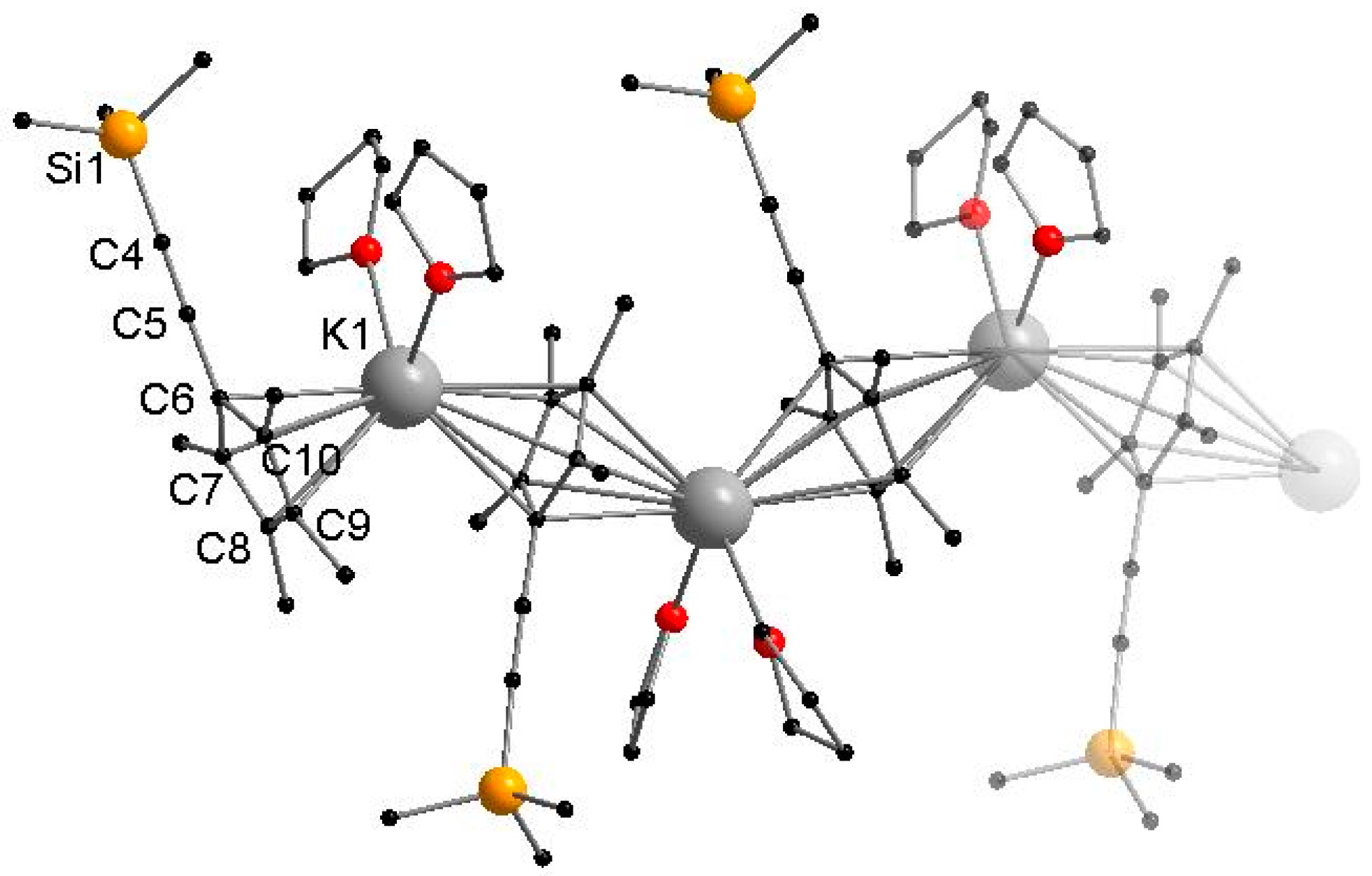
Inorganics | Free Full-Text | Alkali and Alkaline Earth Metal ...
Multi-pass cells for post-compression of ultrashort laser pulses
Cytology Result High Resolution Stock Photography and Images ...

Converging & Diverging Lenses Ray Diagrams DIRECTIONS: Use at ...
Visualization of Tensor Fields in Mechanics
Physics Unit 2 Revision (Higher tier)

Full-field stress computation from measured deformation ...

Mr Toogood Physics - Lenses

Drawing ray diagrams for a converging lens - The Fizzics ...
Please help! I am not good a drawing ray diagrams, | Chegg.com
Solved Draw a ray diagram of the lens system as it should ...
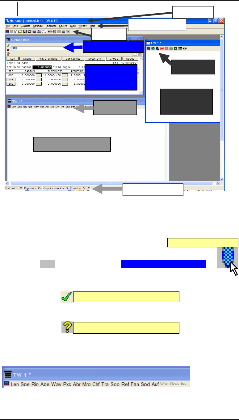
User_Guide_Sept_02_2009 Oslo user guide
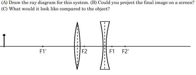
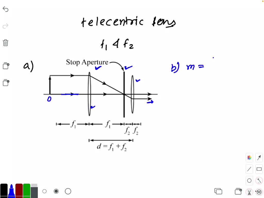
Draw the ray diagram for this system_ (B) Could you pr ...
a draw a ray diagram of the lens system as it should look at the end of step c6 the setup for forming the image of a real image draw the ray diagram roughly to scale and label all lengths ba 52282

Advancing insights on β-cyclodextrin inclusion complexes with ...
Physics Tutorial: Refraction and the Ray Model of Light

Different Lens Ray Diagram questions | Evan's Space
Solved Experiment 1: Ray Diagrams To complete this lab, you ...

US9690115B2 - Contact lenses displaying reduced indoor glare ...

Grading Sphero-Cylinder Spectacle Similarity | OPTO
2. The TEM and its Optics

Draw ray diagrams showing the image formation by a convex lens when an object is placed

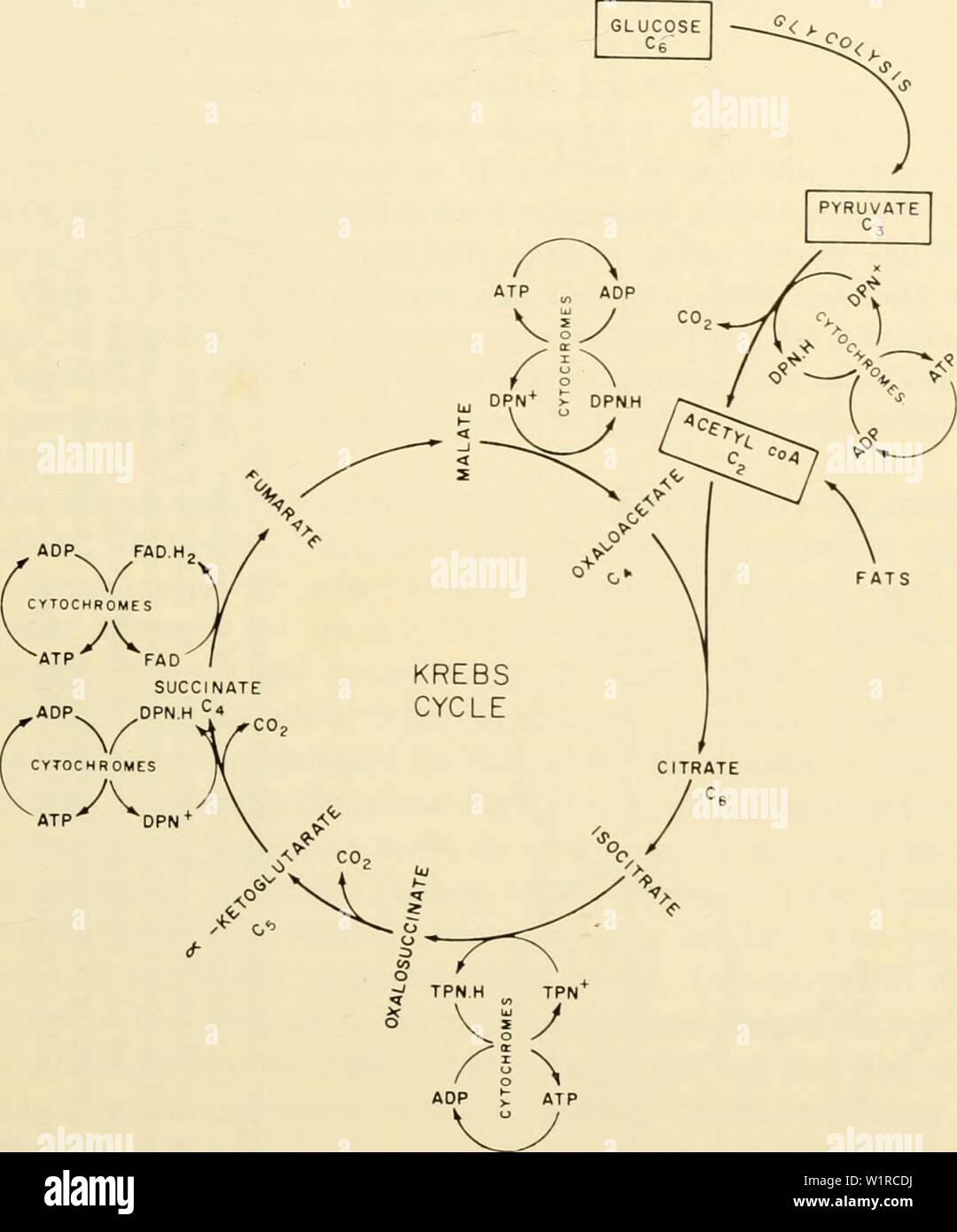
54 Biology ideas | teaching biology, teaching science, biology

Optics Lesson: Not typical Converging Lens light Ray practice questions
Solved 10. Draw a ray diagram for Method I. Use at least two ...

Converging lens ray diagram - Lens F
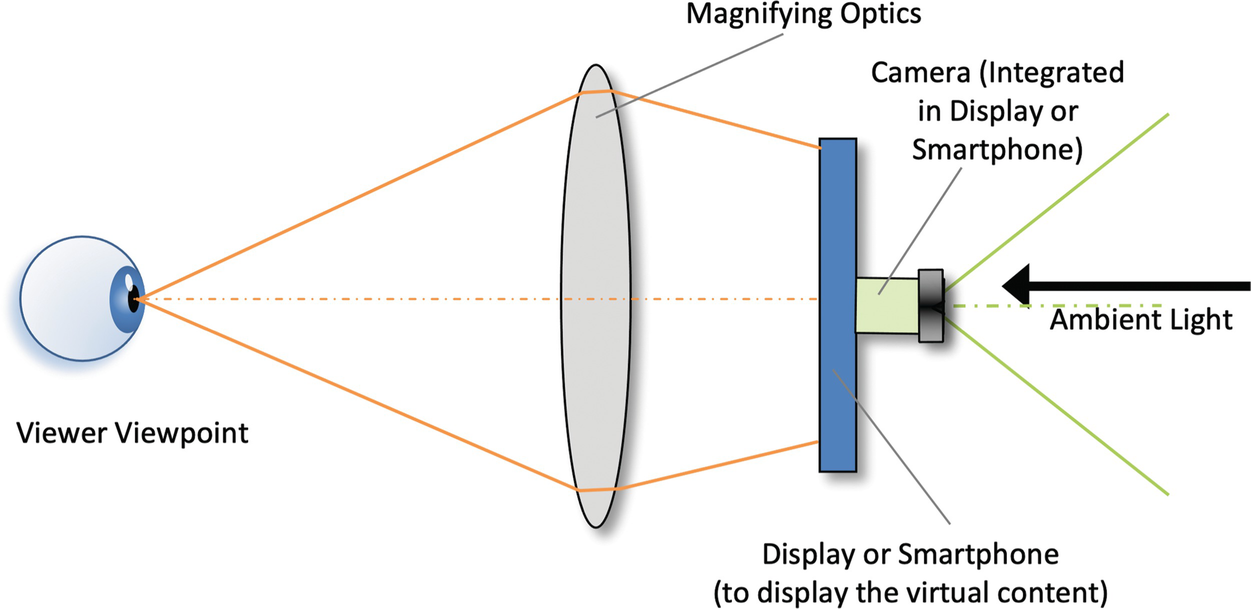
VR/AR Output Devices | SpringerLink
![Solved 10. (1.5 pts] {Section C} a. Draw a ray diagram of ...](https://media.cheggcdn.com/media/d6d/d6dd6d82-3345-431c-89c5-76250c96de1e/phpE9bOUh)
Solved 10. (1.5 pts] {Section C} a. Draw a ray diagram of ...
Off-axis optical levitation and transverse spinning of ...

On Fabry–Pérot Etalon-based Instruments. I. The Isotropic ...
Multipath lens for eye-safe optical wireless communications

Synthesis and physicochemical properties of the methyl-nitro ...
How to draw a ray diagram of a convex lens of magnification of ...

Tribological behavior of stainless steel in sulfuric acid in ...

Course: S4: Physics
Physics Tutorial: Refraction and the Ray Model of Light

Copy of chem/physics questions + answers - techhenzy
Comments
Post a Comment