38 potential relay wiring diagram
Compressor Potential Relay Wiring Diagram - One of the most hard automotive repair tasks that a mechanic or fix shop can give a positive response is the wiring, or rewiring of a car's electrical system. The hardship in reality is that all car is different. subsequent to a pain to remove, replace or repair the wiring in an automobile, having an accurate and detailed compressor potential relay wiring diagram is necessary to the feat of the repair job. 05.04.2021 ... Attach all wires from the old relay to the APR5 using the corre- sponding terminal numbers. TYPICAL APR5 WIRING DIAGRAMS ARE SHOWN BELOW.
I really need to know the pinout (numbers) for the 2010 stereo harness. I have searched for about 3 1/2 hours and come up with absolutely nothing. I have a 2008 mustang that I am putting a 2010 steering wheel on, and am wiring up the controls for volume / track via a SWC module. I need to know what pins 18 and 19 are on the 2010 mustang, and which pins those would be on the 2008 mustang. any help at all would be appreciated more than you know!

Potential relay wiring diagram
Weather king furnace wiring diagram - Ruud Rheem Weather King Furnace Fan questionNov 04 Best Answer. ... 3-pole contactors and overload relays for motor starting and power switching T… Written By ira 17 Sunday, ... Copeland Potential Relay Wiring Diagram. 5425 John Deere Wiring Diagram. Ge Cooktop Wiring Diagram. Rheem Furnace Blower Wiring ... TYPICAL APR5 WIRING DIAGRAMS. Page 2. The SUPR is a potential relay designed to be a wire-by-wire universal replacement for virtually any potential relay on the ... 55 New Potential Relay Wiring Diagram Electrical Circuit Diagram Ac Capacitor Electrical Diagram. 0 75hp 110 220 Single Phase Motor Circuit Diagram Electrical Diagram Electrical Circuit Diagram. 3 Phase Wiring Fuse Panel Home Electrical Wiring Basic Electrical Wiring Distribution Board.
Potential relay wiring diagram. So I just got this today and the search for a data sheet goes to a dead server. https://www.amazon.com/gp/product/B082HKPLFJ/ref=ppx_yo_dt_b_asin_title_o00_s01?ie=UTF8&psc=1 I'm looking to find out what the voltage is supposed to be on the interface side (orange connectors). I thought it was supposed to be 5VDC +/- and the green connectors would be any switch, so you could jump comm to 1..4 and it would switch that relay. However, someone posted on another forum, saying that's wrong and ... The X6 boxed connector X6463, above, indicates that somewhere in that connector an unidentified lead goes somewhere else. The brown wire and the dot-bar indicate ground potential, 'grounded'. I do not have access to ISTA or Windoze. At TIS, schematics have 'eyeball' and 'i' links to symbol and schematic meanings. In the diagram, you can see the use of a draw-out high voltage circuit breaker at 13.8kV marked with double arrows. Coming into the draw-out breaker is a control signal shown as a red dotted line, which comes from the relays. The relays show the current transformers (CT) they are connected to, and the CTs show their CT ratio. Then run a heavy gauge wire from the battery to the relay placing a 30 amp fuse in line very close to the battery. To begin with, look at your relay switch and notice the four prongs on it marked 30, 87,85, and 86. Normally, there are two wires connected to these lights out of which, one is the power wire, normally having a red color, and ...
22.07.2018 · 727 neutral safety switch wiring diagram; 8 pin relay wiring diagram; 8 pin relay wiring diagram pdf; 8 pin rocker switch wiring diagram; 87 supra fuse box diagram; 900 schematic signal stat 900 wiring diagram; 97 honda accord stereo wiring diagram; 97 subaru impreza fuse box diagram; 98 dodge ram trailer wiring diagram; 98 ford expedition ... 25.01.2022 · Use Relay Location and Electrical Wiring Routing sections to find each part, junction block and wiring harness connectors, wiring harness and wiring harness connectors and ground points of each system circuit. Internal wiring for each junction block is also provided for better understanding of connection within a junction block. Wiring related to each system is indicated … Wiring Diagrams. GLASS TERMINAL. OVERLOAD SPRING ... (CSIR) WITH PLUG-IN CURRENT RELAY. 230 V,' 50 Hz. 1. PHASE SUPPLY ... POTENTIAL. RELAY. GLÁSS TERMINAL. Tecumseh Potential Relay Wiring Diagram. 28 Dec, 2022 Post a Comment The motor is a CSCR drive. Yes, they som… Radio Wiring Diagram For 2007 Ford Five Hundred. 06 Dec, 2021 Post a Comment Many people do not understand that an RV has more than just one electri… Ford F350 Transfer Case Wiring Diagram ...
We had one station that was using the classic electro-mechanical relay logic, and mechanical timers of some sort. No one knew how it really worked. There was a group of engineers that tried to push for a proper reverse engineering so they could port to a PLC, half a decade ago. That got shut down. We only realized some of the electrical wiring diagrams were missing or extremely degraded after a recent electrical fire burned up a good chunk of the relay logic controls. While I'm not involved wi... So my 97 Tahoe is needing a light upgrade and i would like to set it up with hids using a relay harness. I would also like all 4 headlights to light up with high beams and this needs a relay as well. I'm looking for the most concise, clean way of installing these light mods. I have an old relay harness for the hids, and can make one for the 4 headlights mod. Thanks for sharing any help Chapter 16 practice quiz, review questions & workbook. Each horizontal line on a ladder diagram represents an individual _____. A device used mainly to detect a particular condition, such as heat or pressure is a _____. Nice work! You just studied 99 terms! Now up your study game with Learn mode. Universal Potential Motor Starting Relay. Wiring Diagram and Cross Reference. RBM. 90-63. Potential Relay. Continuous Coil Voltage 170. Pick Up Minimum 140.

10.3 Potential Relays - 10.4 Solid-State Starting Relays and ...
14.04.2021 · A wiring diagram gives a physical layout of the connection, unlike the schematic diagram. However, it also makes use of abstract symbols to represent some components. You can tell from the wiring harness diagram how complicated or how pure your custom wire harness would be. Ideally, every cable harness circuit diagram will have the following ...
Potential Relays
Does anyone have a wiring diagram for the fuel pump on a 2017 6.7? After a lot of googlefication all I can find is for 7.3, 6.0, and 6.2. I’m installing a kill switch run to an upfitter switch in the cab for theft prevention.

Electrical Relay and Solid State Relays for Switching
You can often rely on wiring diagram being an crucial reference that may assist you to preserve time and money. Two of these take traveler wires that go from one switch to the other. For single pole applications wire the sensor switch according to wiring diagram 1 using the wire nuts provided. For the third terminal one switch is connected to the hot supply wire while the. In this diagram 2 wire cable runs between sw1 and the outlet.
How to wire a 5-pin Boschhorn relay - Quora
2.2 - Wiring the brake controller 6 2.2.1 Red Wire (Vehicle Brake light) Connection 6 2.2.2 Wiring Diagrams 7 2.3 - Mounting the Remote Head 8 2.4 - Active Calibration 9 3 - Operation 10 3.1 - Adjusting the Braking Force 10 3.2 - Manual Override 10 3.3 - Operating Modes 11 3.3.1 - Proportional Mode (Blue LED) 11 3.3.2 - User Controller Mode ...

Overload Relay Connection Diagram and Wiring - ETechnoG
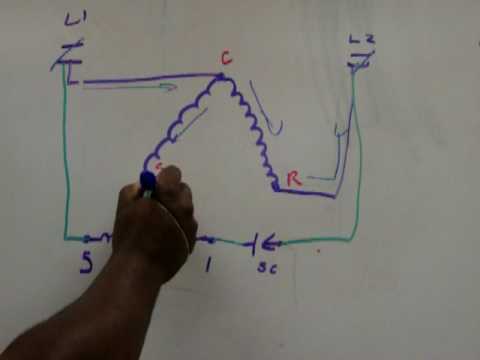
Earth leakage relay wiring diagram ... Volt - unit of electrical potential or motive force - potential is required to... Connection of a 380V three-phase motor on 220v single-phase. When there is a three-phase motor to connect to a single-phase sector, there are several solutions. This is the capacitor assembly that will...

10.3 Potential Relays - 10.4 Solid-State Starting Relays and ...
[http://www.wrxinfo.com/service\_manuals/](http://www.wrxinfo.com/service_manuals/) Been researching some torque specs for suspension stuff and was surprised about the amount of misinformation and confusion out there across forums and videos. Here ya'll go, hope this helps some of you DIYers.
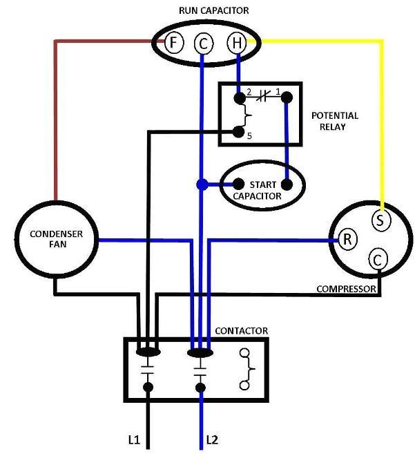
![WRG 8228] Potential Relay Wiring Diagram | Hvac air ...](https://i.pinimg.com/564x/73/ab/e6/73abe674629c0c5126dd4aca577bad05.jpg)
WRG 8228] Potential Relay Wiring Diagram | Hvac air ...
Simatic S7 S7 1200 Programmable Controller Cpu 1214c Wiring Diagrams Relay Electrical Components . Cpu 1214c wiring diagrams. 6es7214 1ag40 0xb0 wiring diagram pdf. 2 ai 0 10 v dc power supply. Cpu 1214c dc dc dc 6es7 214 1ag40 0xb0. 6es7 kfab0 kbab0 wiring diagram 6es7 bcxb0 siemens s cpu 6es7 bcxb0 siemens s7.
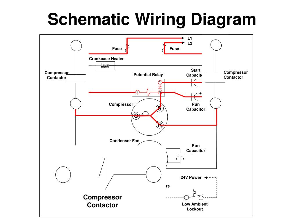
PPT - Symbols, Wiring Diagrams & Meters PowerPoint ...
8 pin timer relay wiring diagram. The electric timer allows a light point to be turned on from one or more places in the room, and to leave this light point on for an adjustable period of time. The control points are pushbuttons with indicator lights (in order to be able to locate them in the event of extinction).

potential relay Archives - HVAC School
potential relay wiring diagram।ac capacitor wiring। relay wiring with starting and running capacitor#potential_relay_wiring ...

Using Current Transformers with Current Sensing Relays
MODEL CA), CAE & AEZ (CSR). Compressor. Thermostat. Potential Relay Compressor. T---7. Overload. ---. 3ooooo. Black. L --- ]. _N_②. Blue. Red/White.
![DIAGRAM] Kenmore pressor Wiring Diagram FULL Version HD ...](https://i.pinimg.com/originals/b3/38/d7/b338d73b5f79b01f78dc6d2bac449071.jpg)
DIAGRAM] Kenmore pressor Wiring Diagram FULL Version HD ...
Compressor Potential Relay Wiring Diagram | Wiring Library - Potential Relay Wiring Diagram Wiring Diagram contains many in depth illustrations that display the link of various items. It contains instructions and diagrams for various types of wiring strategies along with other products like lights, windows, and so on.
Operating and Troubleshooting Potential or Voltage Relays ...
Compressor Potential Relay Wiring Diagram | Wiring Library - Potential Relay Wiring Diagram Wiring Diagram contains many in depth illustrations that display the link of various items. It contains instructions and diagrams for various types of wiring strategies along with other products like lights, windows, and so on.

55 New Potential Relay Wiring Diagram- A govern relay is used ...
Potential Relay Wiring Diagram - compressor potential relay wiring diagram, copeland potential relay wiring diagram, mars potential relay wiring diagram, Every electrical arrangement consists of various distinct components. Each part should be set and connected with different parts in particular way.
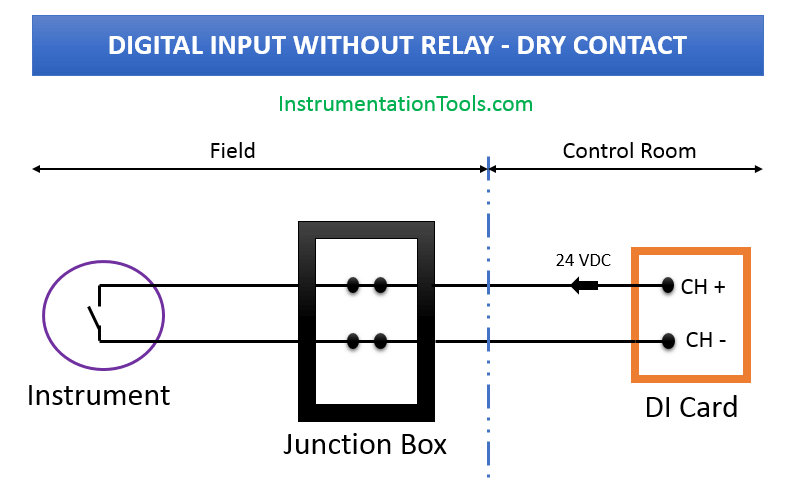
Wiring Diagrams of PLC and DCS Systems - DI, DO, AI, AO
Auto gate wiring diagram malaysia oh 2416 pdf mazda 6 2005 automatic sliding controller system. 60 Luxury 8 Pin Relay Wiring Diagram Pdf Relay Electronic Parts Electromagnet . Kia Wiring Diagrams Free Download For Such Models As Ceed Picanto Rio Sedona Sorento Sportage Venga And For Ot Kia Sportage Sportage Electrical Diagram
E2 Motors and Motor Starting - ppt video online download
UNDERSTANDING TOYOTA WIRING DIAGRAMS WORKSHEET #1 1. Describe the meaning of the "C13" in the diagram component Q. 2. Describe the meaning of the "G-W" in diagram component R. 3. Describe the meaning of the "2" in diagram component S. 4. Describe the meaning of the "S/D" in diagram component T. 5. Describe and identify the diagram …
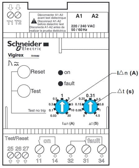
Earth Leakage Relay (ELR)
This model of TIPM is all solid state with no mechanical relays to check. I have been attempting to check the control relay wiring and control PCM outputs/inputs (where I am guessing other potential control relays are located), but am having difficulty finding which wires to check for supply voltage and feedback voltage.

Operating and Troubleshooting Potential or Voltage Relays ...
According to previous, the lines at a 4 Prong Relay Wiring Diagram signifies wires. At times, the cables will cross. But, it does not mean connection between the cables. Injunction of two wires is usually indicated by black dot in the junction of two lines. There will be primary lines which are represented by L1, L2, L3, and so on.

Practical Machinist - Largest Manufacturing Technology Forum ...
Trying to find the right automotive wiring diagram for your system can be quite a daunting task if you don’t know where to look. Luckily, there are some places that may have just what you need. Here’s where to start. Before you search for a...

Using a Potential Relay to Start a CSCR Motor
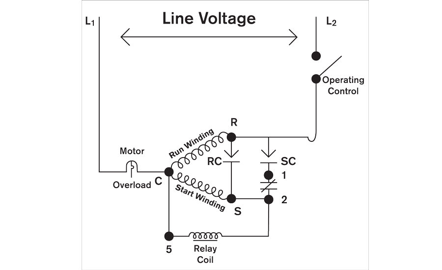
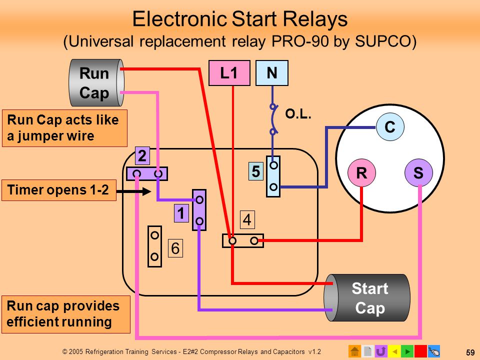
A mechanical Potential Relay connected to a Start Capacitor that is ... 3-wire hard start schematic. Start winding. Run Winding. Potential. Relay.

Compressor Wiring
09.04.2015 ... The highlighted region in the illustration above show the potential relay's wiring path. Potential Relay Connections. Potential relays have 5 ...
Potential relay
A home or vehicle is a maze of wiring and connections, making repairs and improvements a complex endeavor for some. Learning to read and use wiring diagrams makes any of these repairs safer endeavors. These simple visual representations all...

Electrical and Electronics Engineering: Air condition ...
May 19, 2020 - 55 New Potential Relay Wiring Diagram- A govern relay is used in the automotive industry to restrict and regulate the flow of electricity t.
RELAY PROBLEMS
I've dismantled one of my old projects and I'm curious about doing a light show. I checked the wiki and the website, but I can't seem to find a wiring diagram. Wiring the relay seems straightforward enough. Still, I'm always cautious about wiring stuff to the mains, so I try to rely on the wisdom of those who know better. But now with hospitals filling up, I'm being more judicious with my risk taking if you can believe it.

Connection diagram of Digital Relay iv.It should checked ...
Peugeot All Models Wiring Diagrams General . Ge Oven Wiring Diagram In 2021 Electric Stove Electrical Diagram Electric Oven . 55 New Potential Relay Wiring Diagram Electrical Circuit Diagram Ac Capacitor Electrical Diagram . Diagram Of Peugeot 5 Engine Peugeot Diagram Engineering . Peugeot All Models Wiring Diagrams General . Engine Diagram ...
Electrical Motor Wiring Diagrams for Android - APK Download
Potential causes for this code to set are: A defective PCM power relay ... (DVOM), and a wiring diagram. Wiring diagrams can be obtained through the manufacturer (service manual or equivalent) or through a secondary source like All Data. Before purchasing a service manual, make sure that a wiring diagram for the PCM power supply circuit is located therein. Before …

✓ Start Cap With Potential Relay
The wiring diagram for a potential relay is shown in ill 10.7. The potential relay has an advantage over other relays because its contacts are normally closed ...
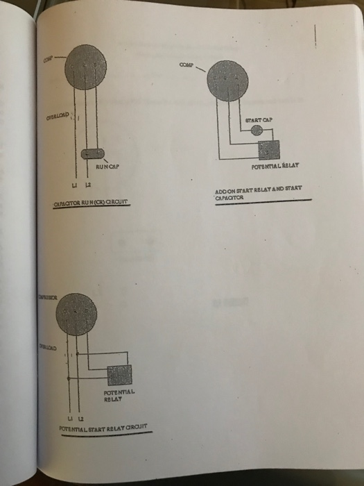
Solved START CAP RUNCAP POTENTIAL RBLAY ADOON START RELATAND ...
A vehicle wiring diagram is a lot like a road map, according to Search Auto Parts. Wiring diagrams are laid out similar to a road map because the diagrams show how each major electrical system, individual circuit and sub-system connects, th...

potential relay wiring diagram।ac capacitor wiring। relay wiring with starting and running capacitor
Potential for good and evil the hard start relay hvac school. The case for hard start kits 2018 04 kickstart device how to install a kit on fix your refrigerator or freezer solutions today s hvac problems ac wiring diagram full potential relay school increases up compressor manualzz capacitor cost replacement 5 2 1 saver starts talk heating air ...
KULTHORN COMPRESSOR
They are usually labeled and identified upon the merge box panel. Motor Capacitor Wiring Auto Wiring DiagramsWiring Diagram FridgeA control relay helps to ...
CAPACITOR SIZING DILEMMAS
55 New Potential Relay Wiring Diagram Electrical Circuit Diagram Ac Capacitor Electrical Diagram. 0 75hp 110 220 Single Phase Motor Circuit Diagram Electrical Diagram Electrical Circuit Diagram. 3 Phase Wiring Fuse Panel Home Electrical Wiring Basic Electrical Wiring Distribution Board.

wiering up a L' Unite / Tecumseh Europe compressor
TYPICAL APR5 WIRING DIAGRAMS. Page 2. The SUPR is a potential relay designed to be a wire-by-wire universal replacement for virtually any potential relay on the ...

Potential Relays - What Happened to Terminal 3? | HVAC
Weather king furnace wiring diagram - Ruud Rheem Weather King Furnace Fan questionNov 04 Best Answer. ... 3-pole contactors and overload relays for motor starting and power switching T… Written By ira 17 Sunday, ... Copeland Potential Relay Wiring Diagram. 5425 John Deere Wiring Diagram. Ge Cooktop Wiring Diagram. Rheem Furnace Blower Wiring ...

Copeland Potential Relay Wiring Diagram Run Capicator For ...
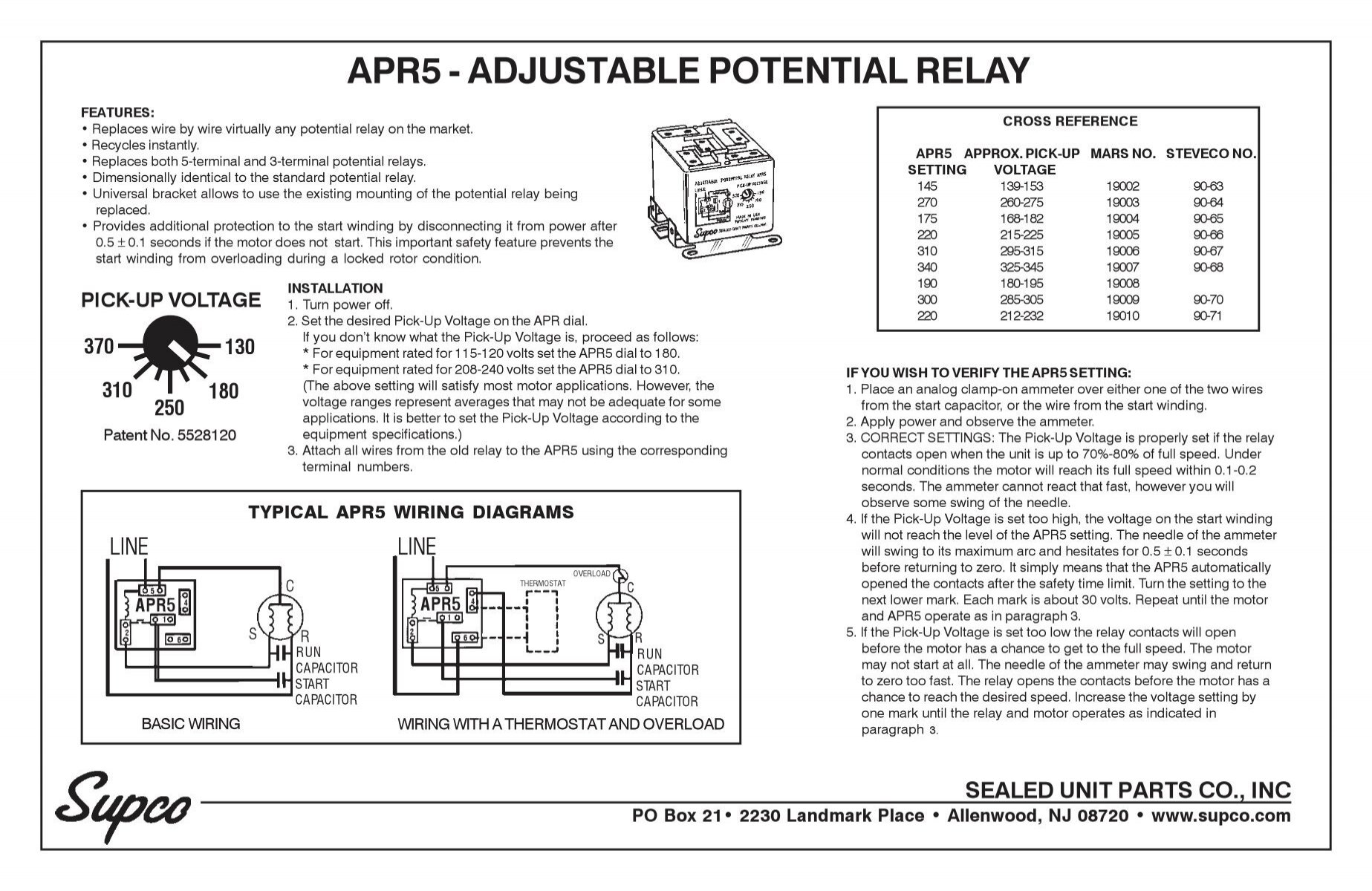
apr5 - supr - Supco

Practical Machinist - Largest Manufacturing Technology Forum ...

10.3 Potential Relays - 10.4 Solid-State Starting Relays and ...

ZCPR datasheet, Pinout ,application circuits MOTOR START ...
KULTHORN COMPRESSOR
Comments
Post a Comment