38 free body diagram with pulley
Example: Free Body Diagrams Determine the tensions in all ropes in the pulley system below. Pulley C is attached at the wall but the other pulleys are suspended. The weights of the pulleys are small compared to the load. Draw the FBD. T A B C 500 kg A simple way to estimate the order of magnitude of the tension would be to draw a diagram (accurate scale) with a straight line from start to finish and two lines to show the shape of the rope with a load on it at about half way. The tension at that position will be about W/(2 SIN(θ)) where W is the load and θ is the angle...
The Best and Completed Full Edition of Diagram Database Website You Can Find in The Internet

Free body diagram with pulley
The Best and Completed Full Edition of Diagram Database Website You Can Find in The Internet free-body-diagrams. T From the above discussions, we have the three equations: This is less than that in case 1 as we predicted. 9. Atwood's machine. Atwood's machine involves one pulley, and two objects connected by a string that passes over the pulley. In general, the two objects have different masses. a a. 10. Re-analyzing the Atwood's ... From the perspective of a free-body diagram the compound pulley system could be replaced by tying two ropes to the load and pulling up on each with a force equal to the effort. The disadvantages of pulleys, in contrast to machines that use rigid objects to transfer force, are slipping and stretching.
Free body diagram with pulley. Free Body Diagram of Cable-Pulley System C The system is held in equilibrium at angle Θ by the tension, T. 30º *Click to see solutions A cable connects pulley A to the ceiling at point C. A Θ T Ignore the weight of the pulley and the cable. B FBD of pulley A TAC y x 30º A TAC= The tension FROM the supporting cable (at 30º) ON the pulley. The block with mass m is hanging from a rope that goes over a pulley which is attached to a block of mass M on a frictionless table. So as the block of mass m falls, the rope will pull the block of mass M across the table. They calculate that T= M M+m mg. Now if I set m:=100M, we will then have T= M M+100M 100Mg≈Mg. This... newtonian-mechanics free-body-diagram string... a pulley with mass 3 Why is the work done by tension in a... Step 2 - Draw a free-body diagram of the pulley. A complete free-body diagram of the pulley, shown in Figure 11.3 (a), reflects that fact that the center-of-mass of the pulley remains at rest, so the net force must be zero. There is still a non-zero net torque, about an axis through the center of the pulley and perpendicular to the page, (the pulley is ! assumed massless); string . B. pulls down on the pulley on each side with a force, T, P , ! which has magnitude . T. B. String . A. holds the pulley up with a force . T, P . with the magnitude . T. A. equal to the tension in string . A. The free-body diagram for the forces acting on the moving pulley is shown in Figure 8.41(d).
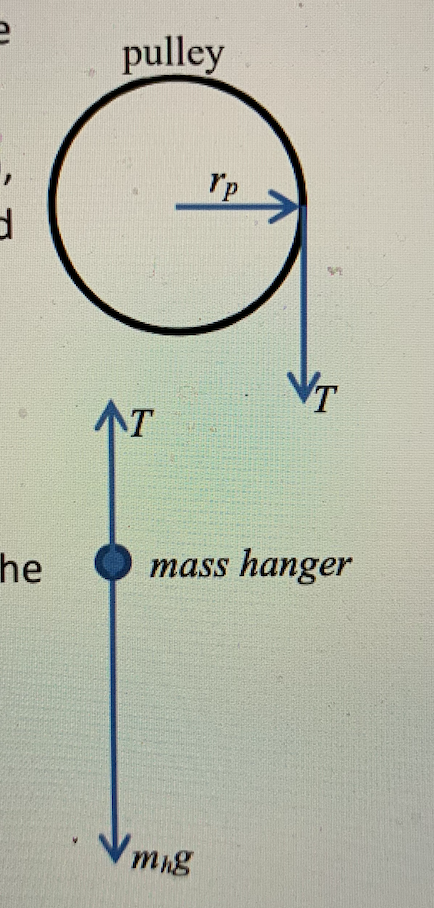
Pulleys and Tension ProblemSum of Forces in Inclined Frames of ReferencePulleys, Tension, and Extension SpringsForces Subscripts ConvectionTwo-Force Members... The Best and Completed Full Edition of Diagram Database Website You Can Find in The Internet R m2 d m1 a. Establish a coordinate system and draw a free body diagram for the two blocks, list the knowns and unknowns. (See sections 1.7 and 5.7 of the text on how to draw a correct free body diagram.) b. Assume the pulley is a rigid body. Draw an extended free body diagram for the pulley. is the radius of the multi-step pulley on the rotary motion sensor and . T. is the tension on the string. Considering the hanging mass (m. H), the analysis from the free-body-diagram tells us that . m H g −T =m H a =m. H (r. α) (2) Combining Eq.(1) and (2), we have . rm H (g −rα) = I diskα, (3) from which . I disk can be determined as H . α
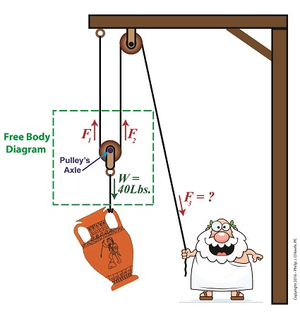
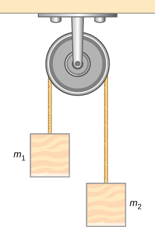
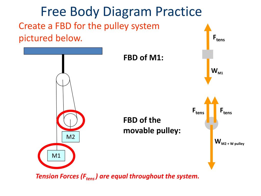
Free Body Diagram Practice M1 M2 FBD of Mass 1: F T FBD of the movable pulley: W 1 W 2 + W pulley F T F T Tension Forces (F T ) are equal throughout the system. Create a FBD for the pulley system pictured below. FREE-BODY DIAGRAMS (Section 5.2) 2. Show all the external forces and couple moments. These typically include: a) applied loads, b) support reactions, and, c) the weight of the body. Idealized model Free-body diagram (FBD) 1. Draw an outlined shape. Imagine the body to be isolated or cut "free" from its constraints and draw its outlined shape. Use the free body diagram of the pulley (Figure 4) to answer the Pre-Lab Questions. 1. Draw a free body diagram for M1. 2. Draw a free body diagram for M2. 3. Apply Newton's 2nd Law to write the equations for M1 and M2. You should get two equations with Tension in the string, weight for each mass and accelerations for each mass (a1. What would the free-body diagram of the balance of forces be for a rope and a pulley: a. For the rope turned 90 degrees? b. For the rope turned 180 degrees? 3. Experiment! Strings, Tension and Pulleys An ideal pulley is one that simply changes the direction of the tension. A man is holding a box at a constant height off the ground by means of a ...
a) A two-pulley belt drive. (b) Free body diagrams of the ...
The Best and Completed Full Edition of Diagram Database Website You Can Find in The Internet
Free Body Diagram | Engineering Expert Witness Blog
The Best and Completed Full Edition of Diagram Database Website You Can Find in The Internet

Free Body Diagrams For any complicated situation, Isolate each object;
#3245 Get Free ACCESS
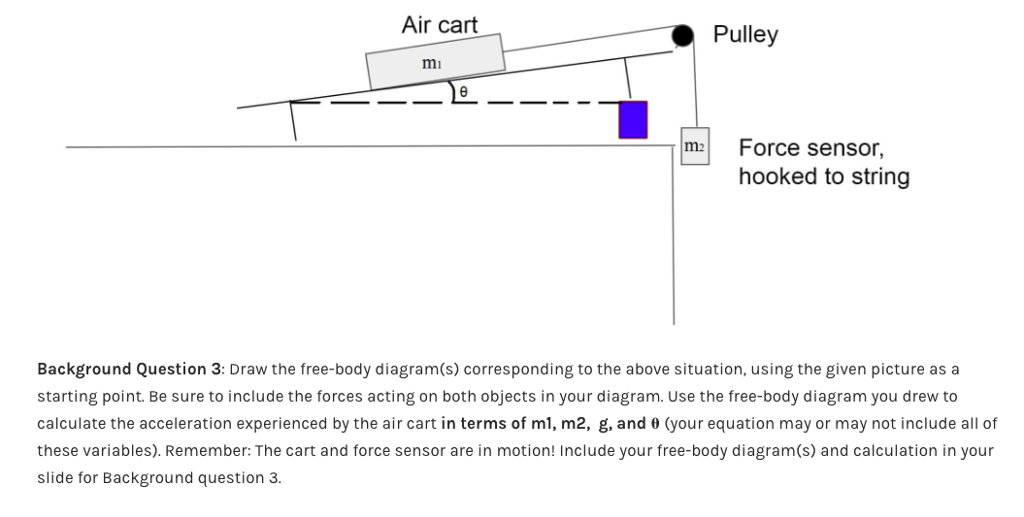
Solved Air cart â—‹ Pulley mi m2Force sensor, hooked to string ...
Using the pulley system illustrated to the right below as an example, the basic method for discussed. As in Lessons 15, 16 and 17, the basic method is to draw a free body diagram of the forces involved, write an expression for the net force, and then solve for the acceleration. In a pulley system two masses are strung over a pulley. Note that ...
eNotes: Mechanical Engineering
The Best and Completed Full Edition of Diagram Database Website You Can Find in The Internet

Solved a) Draw the free body diagram for pulley A. b) Draw ...
Find: Draw the free-body and kinetic diagrams of the crate. Plan: 1) Define an inertial coordinate system. 2) Draw the crate’s free-body diagram, showing all external forces applied to the crate in the proper directions. 3) Draw the crate’s kinetic diagram, showing the inertial force vector ma in the proper direction.

Pulleys - Physics for K-12 - OpenStax CNX
Award Winning Human Anatomy and Physiology Home Study Course - For Practitioners, Students, Medical Professionals,Paramedics & Academia
How to determine value of tension here? - Physics Stack Exchange
• Free body diagram for each element ... • Assume that the pulley is ideal –No mass and no friction –No slippage between cable and surface of cylinder (i.e., both move with same velocity) –Cable is in tension but does not stretch • Draw FBDs and write equations of motion
Help with free body diagram | Physics Forums
The Best and Completed Full Edition of Diagram Database Website You Can Find in The Internet
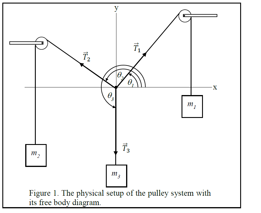
Solved 2 3 Figure 1. The physical setup of the pulley system ...
One normally puts only one free body in a free body diagram. Things get cluttered when you have three bodies. A proper free body diagram could let you see that there is no leftward force acting on the right-hand mass ##m## and that there is a net leftward force acting on the big mass ##M##. It follows that the two will separate at least ...
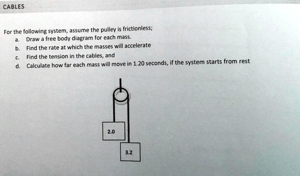
SOLVED:CABLES For the following system, assume the pulley is ...
Coordinate systems and Common acceleration - Pulley in Physics. For an ideal pulley, the tension is the same throughout the rope (therefore the same symbol T in both diagrams). This is generally a common consideration for pulley tension problems. The acceleration a of each subject is indicated. The cart accelerates to the right when the ...

Free Body Diagrams For any complicated situation, Isolate ...
As motion is confined to x-direction, we draw free body diagram considering forces in x-direction only. Free body diagram of pulley.
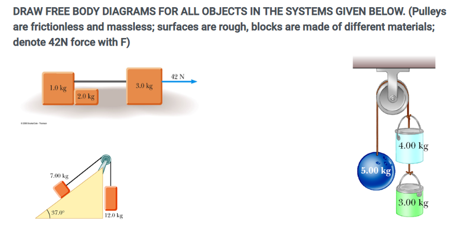
Solved DRAW FREE BODY DIAGRAMS FOR ALL OBJECTS IN THE | Chegg.com
20% off orders over $100* + Free Ground Shipping** Online Ship-To-Home Items Only. Use Code: SHOP4WINTER. Menu. 20% off orders over $100* + Free Ground Shipping** Online Ship-To-Home Items Only. Use Code: SHOP4WINTER. Sign In. Sign In Create Account Earn Rewards Track Order. Find a Repair Shop. CART. Menu. add vehicle. add vehicle.
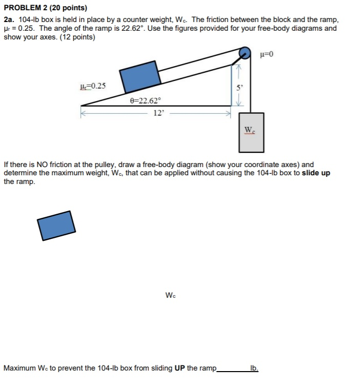
Solved PROBLEM 2 (20 points) 2a. 104-1b box is held in place ...
The Best and Completed Full Edition of Diagram Database Website You Can Find in The Internet

Free Body Diagrams Free Body Diagram Visual representation
We can draw the free body diagram of bob at a as shown in figure 1.43. The force acting on the bob is it's weight mg and tension T of the string. Tenstion T is resolved in two components T cos θ and T sin θ as shown in figure 1.43. we can write the equation of motion. T cos θ = mg T sin θ = mv2/r.

Free-Body Diagram for the th i Pulley/Shaft | Download ...
Making accurate free body diagrams for a system of blocks connected by string and pulleys is an important step towards writing the correct equations of motio...
5.7 Drawing Free-Body Diagrams | University Physics Volume 1
I also have to mention that, because has a greater mass, I initially thought that would be the one sliding downward while lifting toward the pulley, so I tried to rewrite the first system with instead of (leaving untouched). As you can guess, that didn't help. I just want to understand why my reasoning is flawed. I chose the...
Pulley, Table, Ramp Free body Diagrams
Free Body Diagram Examples. Now we will explain the FBD concept, using the following free body diagram example problem as shown in Fig. 1. A 50 kg stationary box must be pulled up a 30 degree inclined by a pulley system.

A mass M is held in place by an applied force F and a pulley ...
Download scientific diagram | (a) A two-pulley belt drive. (b) Free body diagrams of the belt on the driver and driven pulleys from publication: Microslip friction in flat belt drives | The ...
FORCES AND FREE BODY DIAGRAMS - ppt download
Using Newton's second law to conduct a free-body analysis of a single object may have seemed difficult enough. Analyzing the inter-dependent motion of two objects may seem impossible. The Physics Classroom takes the mystery out of the topic with a logical presentation of a process for analyzing two-body problems. An emphasis is placed upon the analysis of Atwood's machines …
Vector statics) Effect of a pulley on free body diagram ...
Question: 2.55 With reference to Figure P2.55 (a) Draw a free-body diagram of the structure supporting the pulley. (b) Draw shear and bending moment diagrams for both the vertical and horizontal portions of the structure. 48 in. -12 in Cable 27 in. 100 lb Cable 12-in. pulley radius 100 lb FIGURE P2.55.

Tension, String, Forces Problems with Solutions
A free body diagram is defined as an illustration that depicts all the forces acting on a body, along with vectors that are applied by it on the immediate environs. Apart from the acting forces and subsequent work done, the moment magnitudes are also considered to be a part of such diagrammatic representations.

Free-body diagram of wheel 1, wheel 2, the pulley and the ...
Please consider the following MWE adapted from this fantastic example of Kjell Magne Fauske's free body diagram: \documentclass{article} \usepackage{tikz} % From http://www.texample.net...

Friction solved problems
The pulley is a solid disk with a mass of 1.25 kg and an unknown radius. The rope passes over the pulley on the outer edge. What is the acceleration of the blocks? As usual, the first place to start is with a free-body diagram of each block and the pulley.

Physics 4.8 Free Body Diagrams (8 of 10) 3 Masses on a Table (With Friction)
Free-Body Diagram Example Problem 3 Bank robbers have pushed a 1000 [kg] safe to a second-story floor-to-ceiling window. They plan to break the window, then lower the safe 4.0 [m] to their truck. Not being too clever, they stack up 600 [kg] of furniture, tie the rope between the safe and the furniture, and place the rope over a pulley.

Choosing signs in free body diagrams of subsystems - Physics ...
Figure 5.6: A diagram for the system of two objects and a pulley. Figure 5.7: Free-body diagrams if there is no friction. (a) The free-body diagram of the red box. (b) An appropriate coordinate system for the red box. (c) The free-body diagram of the red box, with force components aligned with the coordinate system. (d) and (e), a
Draw the F.B.D. (Free Body diagram) of two blocks | Physics ...
Several problems with solutions and detailed explanations on systems with strings, pulleys and inclined planes are presented. Free body diagrams of forces, forces expressed by their components and Newton's laws are used to solve these problems. Problems involving forces of friction and tension of strings and ropes are also included.. Problem 1

(3/8) Simple FBD with Pulley
Since each moveable pulley has two supporting strands emanating from it, the mechanical advantage of the given system is 2n, not 8. This occurs because, assuming the same tension in each supporting strand, there are 2n tension forces pulling the load up. For more info, see

Solved 2B. A 91-lb box is held in place by a counter weight ...
To further test your understanding of free-body diagrams, see our force problems, which include problems where you need to draw free-body diagrams of objects that move up an incline, hang from ropes attached to the ceiling, and hang from ropes that run over pulleys. For each problem, we provide a step-by-step guide on how to solve it.

Statics eBook: Equilibrium & Free Body Diagrams
Is there any difference between the free body diagram of fixed pulley and movable pulley? Not particularly. The main thing is that you can assume the fixed pulley isn't accelerating, so all forces on it must sum to zero. A movable pulley may or may not be accelerating. is it true that fixed pulley has T1 and T2, but movable has T2 on both sides ...
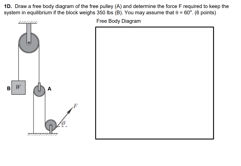
Solved 1D. Draw a free body diagram of the free pulley (A ...
Analyzing it with free-body diagrams (for me the most complicated subject in mechanics I can think of) is at least tricky if not impossible. ... For a pulley aligned with the coordinate system and a 90 degree turn, a different diagonal element will then have the ##-T## term].
solution
B) free body diagram of point P; three forces (upper part of figure below) 1) Tension T 1 2) Tension T 2 3) Tension T 3 Example 8 : A system with two blocks, an inclined plane and a pulley A) free body diagram for block m 1 (left of figure below) 1) The weight W 1 exerted by the earth on the box.
pulleys
Draw the free-body diagram of the beam which supports the 80-kg load and is supported by the pin at A and a cable which wraps around the pulley at D. Explain the significance of each force on the d...
Two-Body Problems
From the perspective of a free-body diagram the compound pulley system could be replaced by tying two ropes to the load and pulling up on each with a force equal to the effort. The disadvantages of pulleys, in contrast to machines that use rigid objects to transfer force, are slipping and stretching.
Solved 1. Draw an extended free body diagram for the pulley ...
free-body-diagrams. T From the above discussions, we have the three equations: This is less than that in case 1 as we predicted. 9. Atwood's machine. Atwood's machine involves one pulley, and two objects connected by a string that passes over the pulley. In general, the two objects have different masses. a a. 10. Re-analyzing the Atwood's ...
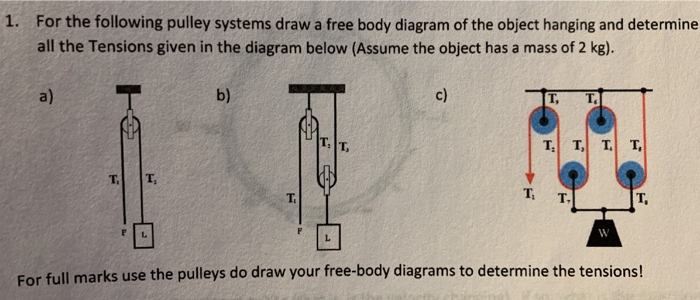
Solved 1. For the following pulley systems draw a free body ...
The Best and Completed Full Edition of Diagram Database Website You Can Find in The Internet

Part 4

Belt and Pulley Devices, the Simple Answer.
Comments
Post a Comment