38 fire alarm horn strobe wiring diagram
Indicating Appliance Circuits connect the fire alarm panel to the components which alert building occupants of the fire, i.e., bells, horns, speakers, strobe lights, etc. The following illustrations show schematics, wiring connections, riser diagram, and wire pull, for some commonly used fire alarm circuits. Fire Alarms Explained is a series where Zach discusses basic concepts of fire alarm systems, as well as showing the specific systems hands on. This is a new ...
ible with the previous generation of SpectrAlert notification appliances. Horn/ strobe products are available in two versions. The 2-wire products fit systems where a single NAC controls both horn and strobe. The 4-wire products are in - tended for systems which have separate wiring circuits for the horn and strobe.
Fire alarm horn strobe wiring diagram
The Genesis Temporal Horn-Strobe is a fire alarm notification The strobe includes a field-configurable switch for selecting the Figure 3: Wiring diagram. 1. 2. vices can be activated by a compatible fire alarm control panel or power sup- ply. Refer to System Sensor wall 4-wire horn strobes are electrically backward compat- ible with the . connection of alarm transmission wiring, communications, signaling, and/or power. If detectors are not so located, a developing fire may damage the alarm system, compromising its ability to report a fire. Audible warning devices such as bells, horns, strobes, speakers and displays may not alert people if these devices are Fire Alarm Horn Strobe Wiring Diagram. Assortment of fire alarm horn strobe wiring diagram. A wiring diagram is a streamlined standard pictorial representation of an electric circuit. It reveals the elements of the circuit as simplified shapes, and the power and signal links in between the tools. A wiring diagram generally provides information about the loved…
Fire alarm horn strobe wiring diagram. Latest information about coronavirus (COVID-19), online services and MyAccount, customer services and how to make a complaint. All horn and strobes shall be wired on alternate circuits. If no FIRE occurs the thermistor will remain at 10 K. Simple Fire Alarm Circuit Using Thermistor Germanium Diode And Lm341 Fire Alarm Circuit Diagram Circuit Install an alarm bell back box and the fire to my house is bells installation sheet automatic alram circuit […] Fire Alarm Horn Strobe Wiring Diagram - fire alarm horn strobe wiring diagram, Every electric structure consists of various distinct components. Each part should be set and linked to other parts in specific way. Otherwise, the arrangement will not function as it should be. Sensiscan 2000 Fire Alarm Control Panel (15017.pdf) N/A: Sensiscan 200 Fire Alarm Control Panel : Manual 15032: N/A: Sensiscan 2000 Fire Alarm Control Panel : Data Sheet df-50439. Manual 15017. Engineering Specification . N/A: MS-5012 Fire Alarm Control Panel with Built-in DACT: Data Sheet df-51186.pdf: N/A: MS-5024(E) Fire Alarm Control with ...
Fire Alarm Horn Strobe Wiring Diagram Circuit Diagram Addressable Fire Alarm System Wiring Pdf. Find this Pin and more on Fire alarm system by Jsimba Mitcham. Demogorgon Stranger Things. Structured Wiring. Lighting Control System. Fire Alarm System. Engineering Works. Diagram Design. on 4 Wire Fire Alarm Wiring Diagram Strobe Panic. Installation and Operation Manual Preparing to Install the FA Fire Panel. Table 12 LED Indicators for NAC Auto SIlence and NAC2 Strobe Mode A user may not be able to operate a panic or emergency switch possibly due to. Connecting a 4-wire smoke detector to a wired alarm system is a slightly The ... 4 wire strobe light wiring diagram. This latter point cannot be stressed enough. This diagram shows the basic wiring of two pull stations and two horn strobes to a power supply. A signal on the red wire will override the steady on running light signal on the black wire and cause the unit to strobe according to my contact at custer. System Sensor PC2WL. The System Sensor L-Series offers the most versatile and easy-to-use line of horns, strobes, and horn strobes in the industry with lower current draws and modern aesthetics. With white and red plastic housings, wall and ceiling mounting options, System Sensor L-Series can meet virtually any application requirement.
49MT-WRF(-BA) Red FIRE New 49MT-WRS-BA Red blank New 49MT-WWF-BA White FIRE New 49MT-WWS-BA White blank New 49AO-APPLW order cover and mounting plate separately New TrueAlert ES Wall Mount Mounting Plates for A/O and MT (horns), V/O (strobes), and A/V (horn/strobes) Reference Model* Color Description According to previous, the traces in a Fire Alarm Horn Strobe Wiring Diagram signifies wires. Occasionally, the cables will cross. But, it does not mean connection between the wires. Injunction of 2 wires is generally indicated by black dot at the junction of two lines. There will be main lines that are represented by L1, L2, L3, and so on. Assortment of fire alarm horn strobe wiring diagram. Fire alarm wiring diagram. It reveals the elements of the circuit as simplified shapes and the power and signal links in between the tools. A wiring diagram is a streamlined standard pictorial representation of an electric circuit. Otherwise the arrangement will not work as it should be. fire alarm horn strobe wiring diagram - You will want a comprehensive, professional, and easy to comprehend Wiring Diagram. With such an illustrative manual, you are going to be able to troubleshoot, prevent, and complete your assignments without difficulty.
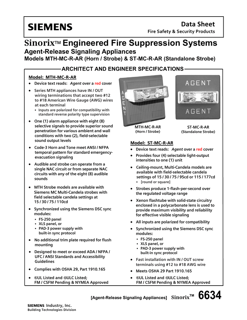
SinorixTM Engineered Fire Suppression Systems
Jul 22, 2020 · Siren Circuit Diagram On Fire Alarm Horn Strobe Wiring Diagram – Fire Alarm Horn Strobe Wiring Diagram. Wiring Diagram comes with a number of easy to adhere to Wiring Diagram Instructions. It is intended to aid all of the typical user in developing a correct system. These instructions will probably be easy to understand and use.
Speaker/Visible Notification Appliance with TrueAlert Non ...
Jul 23, 2020 · Siren Circuit Diagram On Fire Alarm Horn Strobe Wiring Diagram – Fire Alarm Horn Strobe Wiring Diagram. Wiring Diagram comes with a number of easy to adhere to Wiring Diagram Instructions. It is intended to aid all of the typical user in developing a correct system. These instructions will probably be easy to understand and use.

Fire Alarms Explained: Wiring Horn/Strobes
31-01-2022 · FOX FILES combines in-depth news reporting from a variety of Fox News on-air talent. The program will feature the breadth, power and journalism of rotating Fox News anchors, reporters and producers.

Troubleshooting of CE Fire System S3 Alarm in FusionModule1000A
Fire Alarm Circuit Diagram Using Thermistor And 555 Timer Ic. Fire alarm system circuit diagram. Fire alarm systems are wired in industrial factories offices public buildings and nowadays even in homes. The block diagram of fire alarm circuit block diagram can be estimated based something like the requirement and application of project the ...
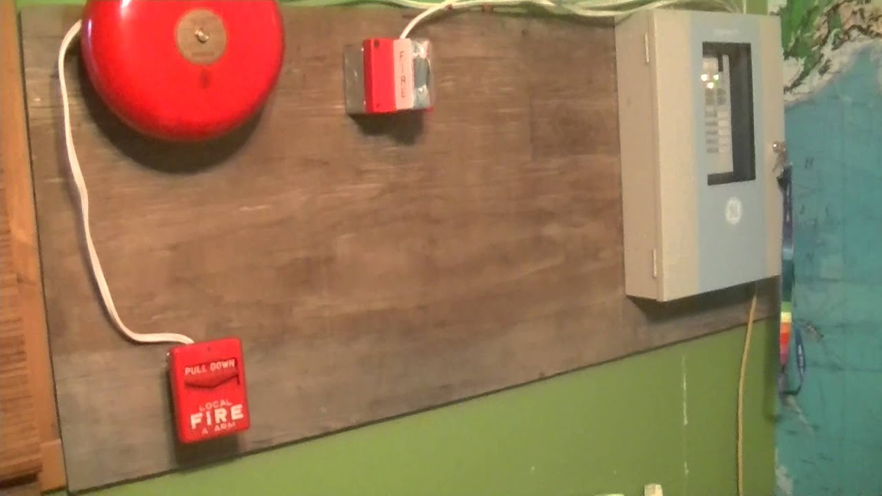
Fire Alarm System Test 1
FIRE ALARM SECURITY ACCESS CONTROL CCTV ... Wiring diagrams provided herein are for information and reference only and are not to be used for installation purposes. ... Integrity: Horns, Horn-strobes: 757 Series 54 Hazardous Location Notification Appliances 55.
Addressable fire alarm systems 2 wire (reset) manual call ...
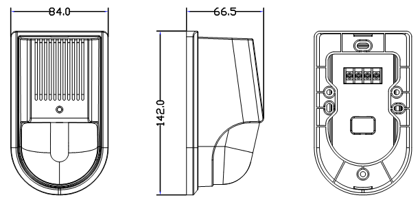
wires around the terminals. To install the horn-strobe: 1. Remove the cover by depressing the tab on the side of the unit with a small screwdriver. Turn the cover counterclockwise to release. 2. Set the horn signal, sound output level, and strobe signal Figure 2. 3. Connect the strobe terminals to the signal circuit field wiring.
ATL-991 Intelligent sound and light siren|Angel Technologies ...
View and Download Kalmar Ottawa t2 maintenance manual online. Ottawa t2 tractor pdf manual download.

How to install Simplex Speaker Strobe | Simplex Fire Alarm Panel | Simplex 4100 ES Addressable Panel
Mar 31, 2018 · fire alarm horn strobe wiring diagram – What’s Wiring Diagram? A wiring diagram is a form of schematic which uses abstract pictorial symbols to exhibit every one of the interconnections of components in a system.
Fire Detection and Alarm Systems
Adding just one more strobe to a fire alarm circuit isn't a problem if the installer knows exactly the strobes that are there already, and the exact length and gauge of the wire. The power supply itself might not be a problem, but the circuit should be calculated using the manufacturer's specifications. Just because the added strobe flashes ...
TrueAlert Addressable Notification Appliances
15-10-2016 · Western 3 Port 3 Plug Wiring Kit Isolation Module Truck Side

Diagram of fire alarm equipment
27-08-2014 · [liblouis-liblouisxml] Re: List of UEB words. From: Ken Perry

BIM Chapters: Low Voltage Distribution in Revit
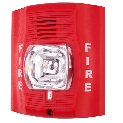
The SpectrAlert Advance P4RKA is a red, four-wire, outdoor horn strobe with selectable strobe settings of 15, 15/75, 30, 75, 95, 110 and 115 cd. Is a red, four-wire, wall-mount, outdoor horn strobe with selectable high-candela strobe settings of 135, 150, 177 and 185 cd. Outdoor back box included.

UHPPOTE Wired 12/24VDC Sound and Light Fire Alarm Warning ...
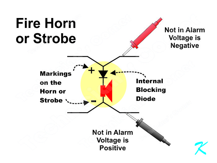
Types Notification Appliance Circuits/Control Circuits (NAC) Supervised polarity reversing power circuits for Horns, Strobes, Bells, Chimes Any NAC that does not have a Notification Appliance attached shall be considered a Control Circuit Performance shall be based upon wiring Class (Note the old Class & Style has been replaced with Class only)

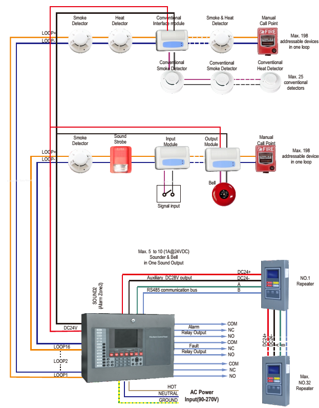
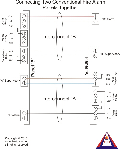
Typical One-line Fire Alarm system Wiring Diagram - Maple Armor
Full membership to the IDM is for researchers who are fully committed to conducting their research in the IDM, preferably accommodated in the IDM complex, for 5 …

Smoke Detector Wiring Diagram | Fire alarm system, Alarm ...
Cooper Fire Alarm Speaker Wiring Example Diagram Strobe wiring diagram wire management diagram bosch fire alarm wiring full version hd quality schematic of the strobe light circuit strobe wiring diagram wire management. Whats people lookup in this blog: Fire Alarm Strobe Light Wiring Diagram
Fire Protection Technicians Network - Fire Alarm Installation ...
The Wooden Wagon is a store featuring wooden toys and games from Europe - We stock a broad selection of natural European wooden toy animals, Ostheimer Waldorf toys, building blocks, marble runs, art and craft supplies, Erzgebirge folk art Christmas decorations, stuffed animals, and natural toys for pretend play.
Fire alarm system - Wikipedia
Related Post: Difference Between Conventional and Addressable Fire Alarm; Wiring Diagram of Heat Detector in Home (AC) Conventional Fire Alarm System. In a conventional fire alarm system, all devices such as detectors, sounders and call points are connected to the control panel through separate wire or cable instead of shared one.

NX / Reliance Installer Manual & Cheat Sheet | SecureFind
Fire alarm control panel designed specifically for ... (refer to diagram on page 4). Unlocking the door provides access to the Acknowledge, Alarm Silence, and System Reset ... For bell/horn/strobe single hazard applications, RAC 2 functions as a third NAC (NAC 3).

outdoor alarm horn,alarm siren,strobe light,LED Firefighting ...
horn/strobe control or with TrueAlert addressable control; for horn/strobe appliance applications, use 4-wire appliances (see data sheet S4903-0011), for horn control, select horn operation as free-run Wire Connections Screw terminals for in/out wiring, 18 to 12 AWG wire (0.82 mm2 to 3.31 mm2)
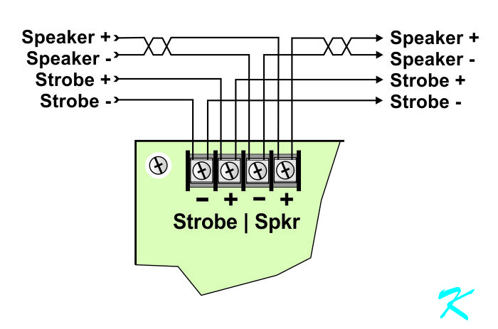
Is This an Addressable 4 Wire Speaker/Strobe?
Fire Alarm Horn Strobe Wiring Diagram. Assortment of fire alarm horn strobe wiring diagram. A wiring diagram is a streamlined standard pictorial representation of an electric circuit. It reveals the elements of the circuit as simplified shapes, and the power and signal links in between the tools. A wiring diagram generally provides information about the loved…
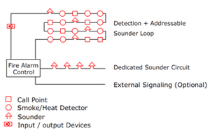
Conventional vs Addressable Fire Alarm System: What Are the ...
connection of alarm transmission wiring, communications, signaling, and/or power. If detectors are not so located, a developing fire may damage the alarm system, compromising its ability to report a fire. Audible warning devices such as bells, horns, strobes, speakers and displays may not alert people if these devices are
WALL MOUNT WEATHER PROOF HORN/STROBES EVCA-AP-SHWP
The Genesis Temporal Horn-Strobe is a fire alarm notification The strobe includes a field-configurable switch for selecting the Figure 3: Wiring diagram. 1. 2. vices can be activated by a compatible fire alarm control panel or power sup- ply. Refer to System Sensor wall 4-wire horn strobes are electrically backward compat- ible with the .

China UL Listed Fire Alarm System Wall/Ceiling Mounted Strobe ...

Troubleshooting of CE Fire System S3 Alarm in FusionModule1000A
Series HS Horn and Horn Strobe Appliances
Fire Detection and Alarm Systems

What is the Difference Between Class A and Class B NAC Circuits?
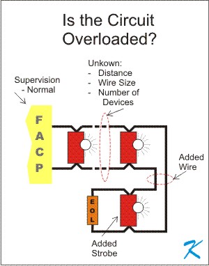
It's just one more strobe, what's the problem?
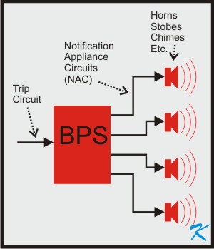
What is a Booster Power Supply or Signal Power Expander?
LifeAlarm Fire Alarm Controls
Multi-Tone Horns; SmartSync Controlled or Free-run; with 520 ...

Fire Alarm Wiring Diagram New Wiring Diagram Manual Call ...
Why Won't the Added Horns and Strobes Work?
Series DSM Sync Modules

Low Cost Burglar Alarm For Boats Circuit Diagram
What You Need to Know: ADA Apartments
Why we use End of Line (EOL) Resistor in Fire and Gas System ?

Fire Alarm Horn Strobe Wiring Diagram Best Of | Fire alarm ...
Comments
Post a Comment