43 university entity relationship diagram
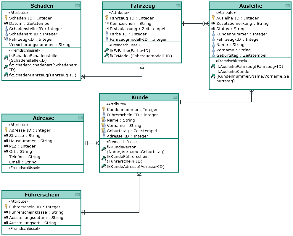
Data & Knowledge Engineering 11 (1993) 171-202 171 North-Holland DATAK 179 GRAQULA: A graphical query language for entity-relationship or relational databases Gary H. Sockut a*, Luanne M. Burns b, Ashok Malhotra b and Kyu-Young Whang c alBM Santa Teresa Laboratory, P. 0. Box 49023, San Jose, CA 95161-9023, USA bIBM Research... ... A Entity Relationship Diagram showing university student housing. You can edit this Entity Relationship Diagram using Creately diagramming tool and include in your report/presentation/website.
Data Flow Diagram A data-flow diagram DFD is a way of representing a flow of a data of a process or a system usually an information system. The Data-flow diagram of our implementation is shown in fig. We were unable to load the diagram. 5 Modules Types of modules are. 52 Project Scope Provides facility for the automated attendance of students.

University entity relationship diagram
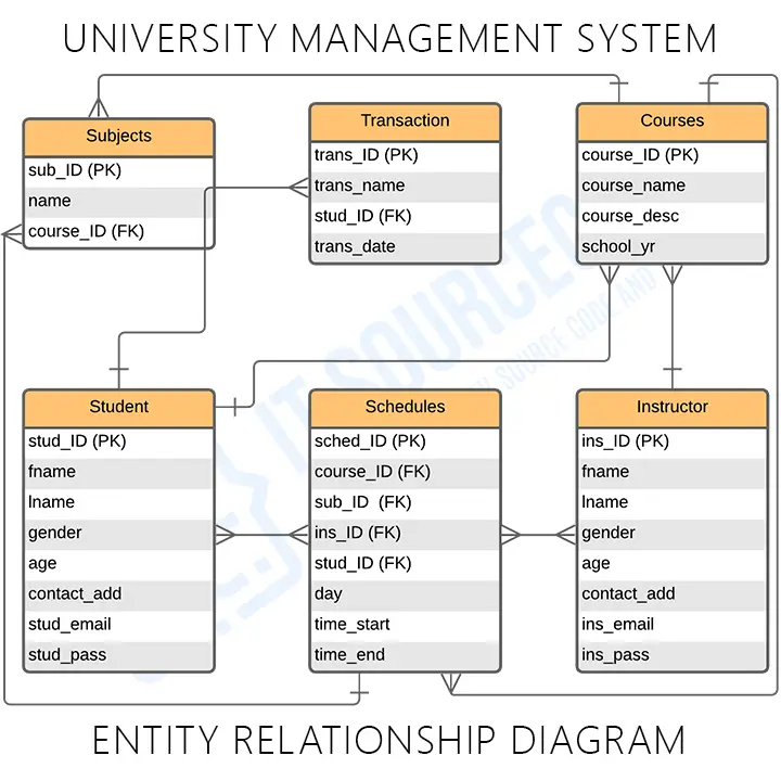
BibTeX @ARTICLE{Chen76theentity-relationship, author = {Peter Pin-shan Chen}, title = {The Entity-Relationship Model: Toward a Unified View of Data}, journal = {ACM Transactions on Database Systems}, year = {1976}, volume = {1}, pages = {9--36} } Share OpenURL Abstract A data model, called the entity-relationship model, is... and hosted by The College of Information Sciences and Technology © 2007-2019 The Pennsylvania State University ... Disc 1: Consider the ER diagram shown in Figure 3.22 for part of a BANK database (also below for reference). Each bank can have multiple branches, and each branch can have multiple accounts and loans. (a) List the strong (nonweak) entity types in the ER diagram. (b) Is there a weak entity type? This ER (Entity Relationship) Diagram represents the model of University Management System Entity. The entity-relationship diagram of University Management System shows all the visual instrument of database tables and the relations between Students, Faculties, Colleges, Registrations etc. It used structure data and to define the relationships between structured data groups of University Management System functionalities.
University entity relationship diagram. Minimum Credits: 3 Maximum Credits: 3 Topics covered include development of enterprise-wide data models using entity-relationship diagrams and semantic data models, logical design and implementation of relational databases, SQL, elements of data structures, and basic issues in the management of the corporate data resource. ER diagrams are also called Entity-Relationship diagrams. These diagrams are fundamental in identifying all the constraints and entities surrounding an information system. It is essential in highlighting the entity’s attributes and the relationship between multiple entities. Extended Entity-Relationship Model -- 9 2004 John Mylopoulos Conceptual Modeling CSC2507 What Does An EER Diagram Really Mean? Course and Room are entities. Their instances describe particular courses (e.g., CSC340S) and particular rooms (e.g., WB116). Meets is a relationship. Its instances describe particular meetings. Each... ... The relational data model and entity relationship diagrams will be covered. Other data models, including the object-oriented model, will be presented. The course introduces database query languages, including an in-depth coverage of the Structured Query Language (SQL).
An Entity Relationship Diagram (ERD) is a visual representation of different entities within a system and how they relate to each other. For example, the elements writer, novel, and a consumer may be described using ER diagrams the following way: ER Diagram Template for Student Enrollment System (Click on image to modify online) In this course, you will create relational databases, write SQL statements to extract information to satisfy business reporting requests, create entity relationship diagrams (ERDs) to design databases, and analyze table designs for excessive redundancy. As you develop these skills, you will use either Oracle, MySQL, or... system using entity relationship diagrams (ER Diagram) which is a representation of the data structures in a table for a company's database. It is a very powerful expression of the company's business requirements. Data models are used for many purposes, from high-level conceptual models, logical to … Data modeling - Wikipedia Entity ... View 3 types of relationship.docx from COMPUTER S COS20015 at Swinburne University of Technology. Entity Relationship diagram / ER Model / Relational Model 1 to 1 relationship Manager ManagerID
The Final ERD Report consists of the Entity Relationship Diagram with the tables created and relationship between them. Run "SQLQueryCreate queries.sql" to setup database with all the tables Run "SQLQueryInsert queries.sql" to populate the database tables Run "SQLQuery queries.sql" to create procedures, views, functions and triggers An Entity–relationship model (ER model) describes the structure of a database with the help of a diagram, which is known as Entity Relationship Diagram Entity-Relationship (ER) Diagrams 29 STUDENT DEPT MINOR_D FACULTY TUTORS CHAIR_F MAJOR_D Tutor Tutee 1 1 N M N M All departments have a faculty member who serves as the chair. A faculty member can only chair one department. N 1 SqlDBM - Online Database Modeler ... Strategic Partner Snowflake Snowflake is the only data platform built for the cloud for all your data & all your users. You can create database models, generate DDL script, and utilize all Snowflake-specific features. More than 600 companies use SqlDBM for their Snowflake projects. Data management partner Microsoft Azure Synapse Analytics Azure Synapse is a limitless analytics service that brings together enterprise data warehousing and Big Data analytics. It gives you the freedom to query data
A simple entity-relationship diagram for university ...
This resolution is done in order to store additional information which doesn’t fit into the attribute list of either entity in the M:M relationship. For instance, in the instructor-course example given earlier, there is a M:M relationship between Course and Section. A course can have many sections, and a section can have many...

White petals with blue center
Likewise, an Extended Entity Relationship (EER) diagram is an advanced version of ER diagram that manages the increasing complexity of the data. This extended ER diagram also introduced various concepts such as Specialization, Generalization, Aggregation, etc. Also: Pagination in SQL Server, MySQL and Oracle with Examples

Er Diagram For University Database - Free Wiring Diagram
Design database with Entity Relationship Diagram tool (ERD tool). Create conceptual, logical and physical database design. Generate database and DDL from ERD and more.

#film #animal #Holliday #bird #parrot #pets #person #boy
Video created by 콜로라도 대학교 for the course "SRS Documents: Requirements and Diagrammatic Notations". At a lower level, Entity Relationship Diagrams, Data Flow Diagrams, and SADT diagrams can be used...
Create a Normalized Entity-Relationship Diagram (ERD) to ...
Document database table schemas using entity relationship diagrams (ERD) Review and comprehend existing code and processes; Develop and publish standard and ad-hoc reports; Collaborate with Advancement users to identify, translate and document business needs as they relate to supported database structures
Entity Relationship Diagram Example: University ...
I've made the following Diagram Which is attached and the following is the scenario for it. The tool I've Used in Visual Paradigm Community Edition. Scenario: Draw an ERD at both Subtype and Supertype levels, following Business Rules: • Each Store is managed by a manager, and each manager only manages one Store. • Each...

hold me tight
may 21 2013 middot the relationship room to class is considered weak non identifying because the primary key components cid
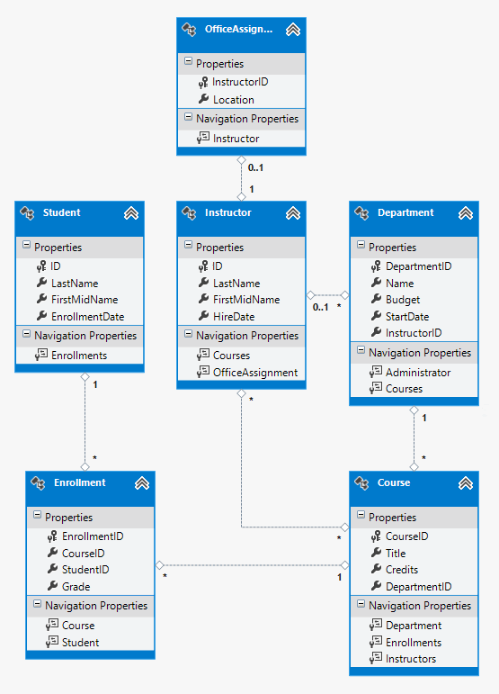
MVC 5 with EF 6 in Visual Basic - Creating a More Complex ...
A class diagram is a collection of classes similar to the one above. Relationships in Class Diagrams Classes are interrelated to each other in specific ways. In particular, relationships in class diagrams include different types of logical connections. The following are such types of logical connections that are possible in UML: Association

Entity Relationship Diagrams | Viterbi Research | Pinterest
ERM'S STEPS The flow of information as the end-user reviews it is depicted in an Entity-Relationship Model (ERM) diagram. Business entities, their attributes, and the interactions between them are all represented in an ERD diagram.
Case Study: Entity Relationship Diagram (ERD) for Student ...
I am implementing a small database(university Project) and i am facing the following problem. I created a class diagram where i have a class Train {Id, Name... I represented the relationship train - rolling stock as a diamond filled (UML) but still I have a many to many relationship between the two tables. so i guess i have to...
Er Diagram Uml Notation | ERModelExample.com
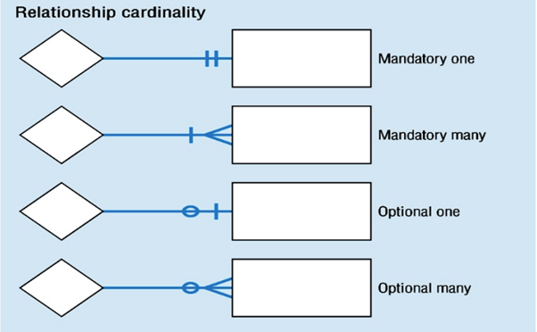
Express-g diagram is also a commonly used ER diagram type. It is a standard graphical notation for information models. From Edraw express-g diagram library, you can get extensive data type symbols of the express-g notations, such as entity, enumerate type, select type, boundary, pointer, cardinality, inverse cardinality, normal relationship, etc.

, Library System Entity Relationship Diagram | Download ...
Create and submit an ER Diagram with at least two tables and their attributes. Your diagram should include: Table Names (for each entity) Attributes (first name, last name, city, etc.) Primary Keys; Foreign keys; Relationships; Field types (text, currency, numeric, date) Your tables should be should be normalized (first, second and third normal ...
Entity Relationship Diagram Example With Explanation ...
My question is: In order to exist which of the following needs obligatory to have key and attribute?I know my question is a little bit odd, but I am not quite sure what are the rules by building an ER-Diagram. In other words what should mandatory be present in my diagram and what not (e.g Attributes). Thanks in advance.

A beautiful tree on Purdue University's campus.
Design a database that follows the rules of normalization and entity integrity using entity relationship diagrams (PLO 2 - I). Create a functional business database from an entity relationship ...

Sample Er Diagram For Student Database - Idaman
The entity-relationship diagram of School Management System shows all the visual instrument of database tables and the relations between Students, Teachers, Schools, Registrations etc. The major benefits of having a fully-featured school management system for school are: 1.

Entity Relationship Diagram for Student information system ...
For tax lawyers and accountants, a major pain point is the time they spend drawing complex entity and relationship diagrams -- diagrams that map the major players involved in a client's tax scenari...

Entity-relationship Model for Delegation | Download ...
Dominican University's beautiful campus is located in River Forest, Illinois right outside of Chicago. Dominican University offers students a wide range of excellent academic programs with small class sizes and a low student-to-faculty ratio. ... functional dependency and entity relationship diagrams, database design, recovery, security ...

University Database Management System Er Diagram ...
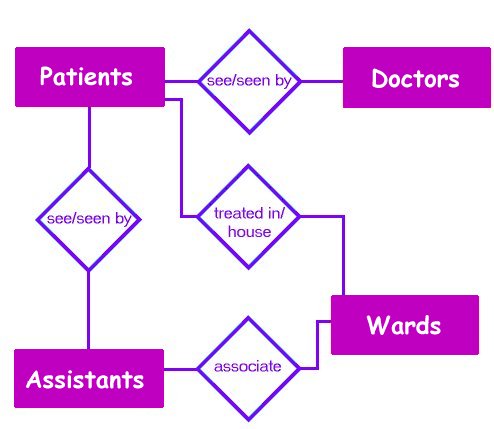
Hospital Management System Relationship Diagram Hospitality Management Database Design . Ministry of Higher Education and Scientific Research University Of Technology Computer Engineering Department ospital Management System Design and Implementation BY In many implementations this is a comprehensive integrated information system designed to manage all the aspects of a hospital.
Er Diagram For University Admission System ...
Analyze the key ways that entity relationship modeling helps database developers overcome potential design challenges and conflicting goals. For the database that you described in the Week 1 and Week 2 discussions, determine the major / minor challenges that might exist when you are creating an entity relationship diagram (ERD) for the business ...

Enrollment system ERD | DIMLIGHT
Storey, Computer Information Systems Department, Georgia State University Abstract The entity-relationship model has long been employed for conceptual modeling of... n-ary relationship sets and for the special case where the E-R diagram depicts a database where 3NF is not in BCNF. It then presents design modeling guidelines... eLibrary Login FAQ About Home Home > Journals > AIS Journals > CAIS > Vol. 29 (2011) Download Share Journal... ...

University Registration Office | Entity Relationship ...
There are many ways you can draw ER diagrams. Learn more by visiting our articles on How to Draw an ER Diagram Online and Top 7 Entity Relationship (ER) Diagram Online Tools. Creating External Tables in Snowflake. A Snowflake ER diagram would not be complete without external tables. Vertabelo provides you with convenient ways of creating them.
University Management System ER Diagram | Entity ...
Books Database Features Screenshots Filter words Insert and filter books Search phrases Statistics Schemes Entity relationship diagram XML format. readme.md. Books Database. SQL Project for University, written in python3 using: sqlite3; PySimpleGUI; Tkinter; Features. Insert new books; Filter the books by author, title, or content; Filter all ...
ER Diagram: Entity Relationship Diagram Model | DBMS Example
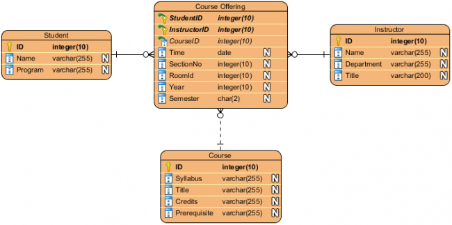
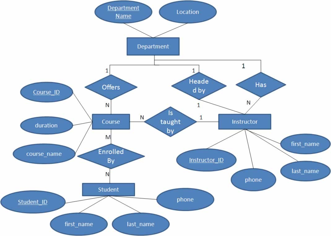
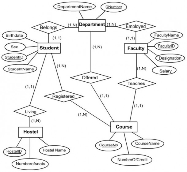
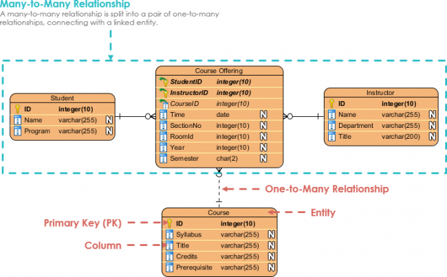
This ERD example models the following information. 1. A Course has an ID (for unique identification), syllabus, title, credits and prerequisites. 2. A Student has an ID (for unique identification), name, and program. 3. An Instructor, has an ID (for unique identification), name, department, and title. 4. A Student may enrol into one or more […]
Example Of Erd Diagram : Newspaper Management System ...
Entity Relationship Diagram. Entity Relationship Diagram (ERD), a database design tool that provides graphical representation of database tables, their columns and inter-relationships. ERD is the most popular database design tool.

Relational Database Schema Diagram | ERModelExample.com
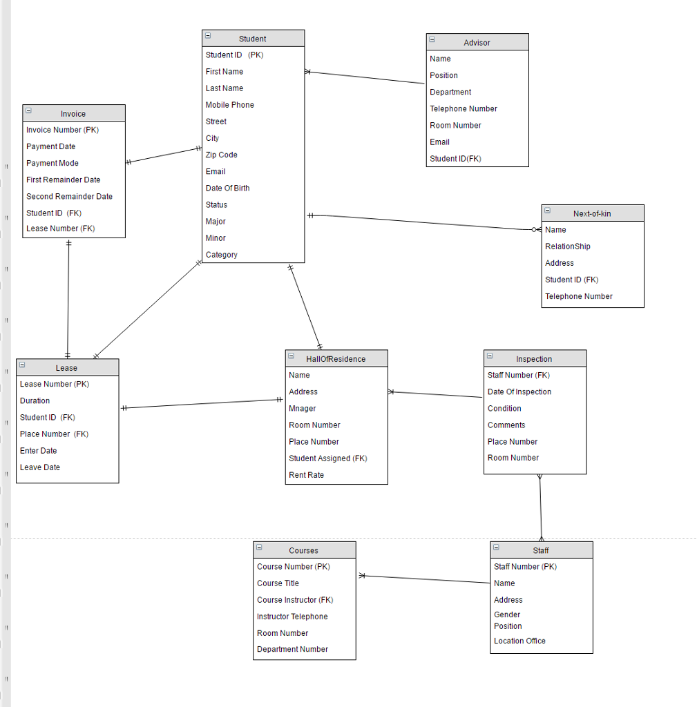
This ER (Entity Relationship) Diagram represents the model of University Management System Entity. The entity-relationship diagram of University Management System shows all the visual instrument of database tables and the relations between Students, Faculties, Colleges, Registrations etc. It used structure data and to define the relationships between structured data groups of University Management System functionalities.
Online College Magazine ( Entity Relationship Diagram ...
Disc 1: Consider the ER diagram shown in Figure 3.22 for part of a BANK database (also below for reference). Each bank can have multiple branches, and each branch can have multiple accounts and loans. (a) List the strong (nonweak) entity types in the ER diagram. (b) Is there a weak entity type?

Designing basic model and E-R Diagrams
BibTeX @ARTICLE{Chen76theentity-relationship, author = {Peter Pin-shan Chen}, title = {The Entity-Relationship Model: Toward a Unified View of Data}, journal = {ACM Transactions on Database Systems}, year = {1976}, volume = {1}, pages = {9--36} } Share OpenURL Abstract A data model, called the entity-relationship model, is... and hosted by The College of Information Sciences and Technology © 2007-2019 The Pennsylvania State University ...

How To Draw One To Many Relationship In Er Diagram ...

University Registration Office | Entity Relationship ...

Case Study: Entity Relationship Diagram (ERD) for Student ...
![Entity Relationship Modeling Examples - Learning MySQL [Book]](https://www.oreilly.com/library/view/learning-mysql/0596008643/httpatomoreillycomsourceoreillyimages234887.png)
Entity Relationship Modeling Examples - Learning MySQL [Book]
Design A Database Using An Entity Relationship Diagram For ...

Er Diagram Assignment Solution - ERModelExample.com
Entity Relationship Diagrams
Entity Relationship Diagram Example: University ...

Entity-relationship (ER) diagram of the CI element state ...

TechMight Solutions: November 2012

Lost in time

27 Good Entity Relationship Model Diagram Samples, http ...

Er Diagram For University Database | ERModelExample.com

Glass and bars of steel create a geometric pattern on a building on Northwestern's campus in Evanston.

Data Modeling and Entity Relationship Diagram (ERD)
TechMight Solutions: Entity Relationship Diagram for ...
Comments
Post a Comment