43 single phase generator winding diagram
Note how much simpler and “cleaner” the single-line diagram is compared to the schematic diagram of the same power system: each three-conductor set of power wires is shown as a single line, each transformer appears as a single primary winding and single secondary winding (rather than three of each), each motor and generator is a simple ... A Repulsion Electric Motor is by definition a single phase motor which has a stator winding arranged for connection to the source of power and a rotor winding connected to a commutator. Brushes and commutators are short-circuited and are placed so that the magnetic axis of the rotor winding is inclined to the magnetic axis of the stator winding.
CONNECTION DIAGRAMS The following are the most common connection arrangements utilized with Mecc Alte generators. Always verify that the connections of all the leads from the main stator are consistent with the nameplate voltage required. Connection diagrams are supplied with every generator and should be used as the primary source of information.

Single phase generator winding diagram
Single Phase Outputs On some STAMFORD alternators, it is possible to reconnect a winding designed with 12 leads for a 3-phase output into a Double Delta configuration for a single phase output. Refer to the alternator's published technical data for the output kVA rating at a single phase voltage. More information is available in AGN154. shaft of the single phase induction generator and generated 220V a.c. voltage for distributing electric load. The design of single phase induction generator is modified by rewiring the winding of an old 1 HP, 220 V, 50 Hz motor from 4 poles to 6 poles. For impulse turbine design, this paper use the information model from Baan Kiriwong The Double Delta connection is commonly used to utilise a 3-phase winding for a single phase output. This reconnection provides the possibility of a mix of 240V and 120V outputs simultaneously, but the current through the bottom leg when 240V and 120V are being taken, must not exceed the total current of 200A (48kVA / 240V). ...
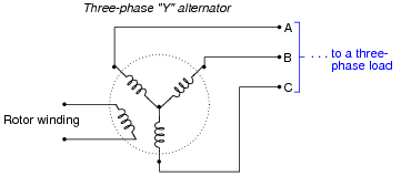
Single phase generator winding diagram. The power generation scheme consists of a three-phase star- connected induction machine with three capacitors: C p and two C s 's, and a single-phase load (Fig. Single-phase generator (also known as single-phase alternator) is an alternating current electrical generator that produces a single, continuously alternating voltage. Single-phase generators can be used to generate power in single-phase electric power systems. However, polyphase generators are generally used to deliver power in three-phase distribution system and the current is converted to ... In power engineering, a single-line diagram (SLD), also sometimes called one-line diagram, is a symbolic representation of a three-phase electric power system.. The one-line diagram has its largest application in power flow studies.Electrical elements such as circuit breakers, transformers, capacitors, bus bars, and conductors are shown by standardized schematic … There are two magnetic poles, north and south, attached to a rotor and two coils which are connected in series and equally spaced on stator. The windings of the ...Designs · Revolving armature · Revolving field · Power stations
Single Phase Motor Wiring Procedure. 1. First, identify the starting winding and running winding terminals by measuring the resistance. 2. Connect any one terminal of each winding together, and it is to be connected to the neutral terminal of the power supply. 3. Lets go through a industrial single line diagram. When interpreting a single line diagram, you should always start at the top where the highest voltage is and work your way down to the lowest voltage. This helps to keep the voltages and their paths straight. To explain this easier, we have divided the single line into three sections. Three phase generators a three phase ac generator as the name implies has three single phase windings spaced so that the voltage induced in each winding is 1200 out of phase with the voltages in the other two windings. Diagrams for wiring 3 and 4 prong dryer outlets. Common 12 lead generator wiring diagrams series wye 416480v 3o voltage l l. Mecc Alte ECP series is 1 or 3 phase, brushless, RPM, AVR controlled generator with Aux Winding. It can power from 8kVA to kVA. Dec 14, · A friend has a small diesel generator that he and I have been restoring. Its maybe 10 years old and looks like it is built to survive an atomic explosion. We got it . the relevant diagram in figure 7.
the winding can thus be controlled by controlling the amount of current passing through the conductor causing the magnetic field. The three- phase generator is basically three separate generators in one casing. It has three completely separate windings in which current is produced, but a single rotating magnetic field. Single Phase Synchronous Generators with Two Stator. Windings: The connection diagram of stator windings is presented in Fig. 1, the two windings – the main and ...4 pages current during a single-phase-to-ground fault. The resistor is selected so that the active power (kW) loss of the resistor is equal to the reactive power dissipated by the equivalent capacitance of the generator (this is the sum of the generator winding capacitance, cabling, and generator surge capacitors) during a single-line-to-ground fault. Winding Setup For A 36 Slot 4 Pole Squirrel Cage Induction Motor Scientific Diagram. Types Of Single Phase Induction Motors Split Capacitor Start Run Electrical4u. 4 Pole Single Phase Ac Motor Wiring Electric Motors Generators Engineering Eng Tips. Schematic Of 36 Slot 4 Pole Stator Winding Generated With The Bobisoft Scientific Diagram.
Motor Rewinding Diagram Pdf | Webmotor.org
Connection diagram of the single phase induction generator scientific small sel generators wiring diagrams wind full version hd quality diagramland andreapendibene it 208v and 3 can i run loads with a three yup green mountain changing over to supply or power mid america engine polyphase motor page types ac electrical a2z voltage changes 277 480 ...

yellow petaled flower close-up photography
Single Phase Motor Wiring Diagram With Capacitor - baldor single phase motor wiring diagram with capacitor, single phase fan motor wiring diagram with capacitor, single phase motor connection diagram with capacitor, Every electrical arrangement is made up of various unique pieces. Each component ought to be placed and linked to different parts in particular manner.

black and silver cruiser motorcycle
In a single phase AC generator, the armature conductors are connected in series so as to form a single circuit which generates a single-phase alternating emf and hence it is called single-phase alternator. The simplified version of a AC generator is discussed here. Consider a stator core consisting of 2 slots in which 2 armature conductors PQ ...
12 Volt Wind Turbine Wiring Diagram
A vector plot of voltages and currents within one phase is called a phasor diagram. A phasor diagram of a synchronous generator with a unity power factor (resistive load) Lagging power factor (inductive load): a larger than for leading PF internal generated voltage E A is needed to form the same phase voltage.

June 2014 | Electrical Winding - wiring Diagrams
Single phase power system schematic diagram shows little about the wiring of a practical power circuit. Depicted above, is a very simple AC circuit.If the load resistor’s power dissipation were substantial, we might call this a “power circuit” or “power system” instead of regarding it as just a regular circuit.

Marelli Generator 225 Kva Winding Diagram | Electrical ...
Single Phase Generator Wiring Diagram. Connection diagram of the single phase induction generator scientific small sel generators wiring diagrams china 2p 100a wireswiring for transfer switches residential changeover switch 750kv mcr temperature rise test is a self regulated excited electerical engineering and tecnolgy manual portable 8 43 00 ...

June 2014 | Electrical Winding - wiring Diagrams
11-12-2014 · Hi Nasir, You can try to use VFD or inverter to drive your submersible pump.The inverter input power supply is single phase 240V and it will convert to 3 phase output to your motor.But please consider your Inverter current (ampere) rating same rated or higher than motor FLA.Rule of thumb to sizing your inverter is –> FLA x 2 = VFD current rating.

Wind Turbine Generator Wiring Diagram
22-11-2021 · Single line diagram (SLD) We usually depict the electrical distribution system by a graphic representation called a single line diagram (SLD). A single line can show all or part of a system. It is very versatile and comprehensive because it can depict very simple DC circuits, or a very complicated three-phase system.

The essentials of power-generation systems you MUST know ...
generator diagram&winding full formula satting , how to make g experiment, generator wiring diagram, how to
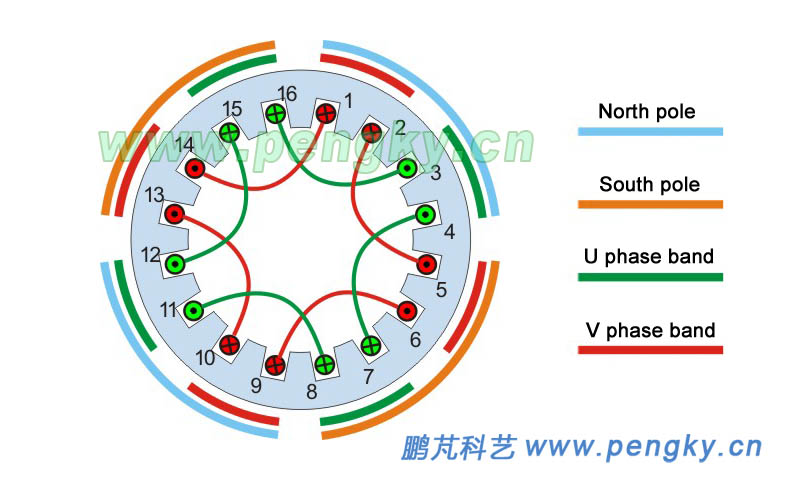
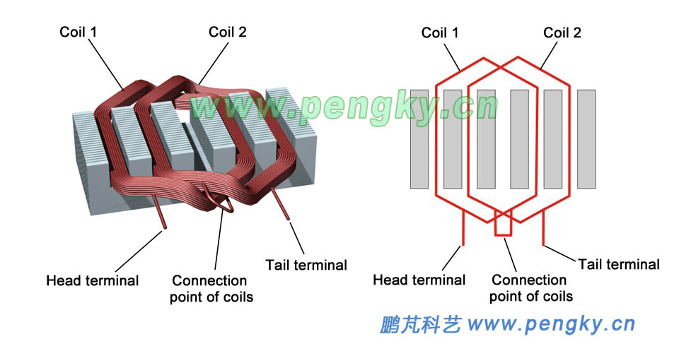
AC Motor Winding | Generator Series Courseware | Pengky
In order to draw the winding diagram, first of all draw the coil sides and number them. Now to make connections start from any coil side, say with first coil side. In order to get the coil side to which the 1st coil side is to be connected at the back, add back pitch to it.
Polyphase Power Systems | AC Electric Circuits Worksheets
Main Stator: Three Phase • Three windings. • For each phase, there is one group (one or more coils) for each rotor pole. - A group is interconnected - Can be considered as one large coil. • The leads are typically wye (star) connected. The neutral is usually connected to ground or brought out with single-phase loads. 2 poles 6 groups

empty concrete road
Two Ways of Three Phase Transformer Connection. A three-phase transformer in an electrical substation can be built in two ways. By suitably connecting a bank of three single-phase transformers ; By constructing a three-phase transformer on a common magnetic structure.; In either case, the windings may be connected in four different connection methods.

red bmw m 3 parked on street
Single phase generator Winding diagram. winding diagram of this product may help you to see where exactly the components rest in the housing and how they cooperate as a system. So we put a PDF file below to make it easier to understand what we mentioned earlier in two previous sections.

Single Layer Winding Diagram 1500 Rpm In series and ...
Single Phase System. The sinusoidal alternating voltage having a specific time period and frequency generated by a single winding alternator as source voltage is known as a single phase supply system. A circuit fed up by these voltages is known as a single phase AC circuit.

Image from page 301 of "The Street railway journal" (1884)
Real single phase transformer 7 Wound leg LV winding HV winding Return core leg In order to better control the stray flux distribution, both windings are wound on same core leg Equivalent Circuit 8 Rp+jXp Rs+jXs X m R m Load Rp+Rs ' Xp+Xs' X m R m Load

waves crashing on sea during daytime
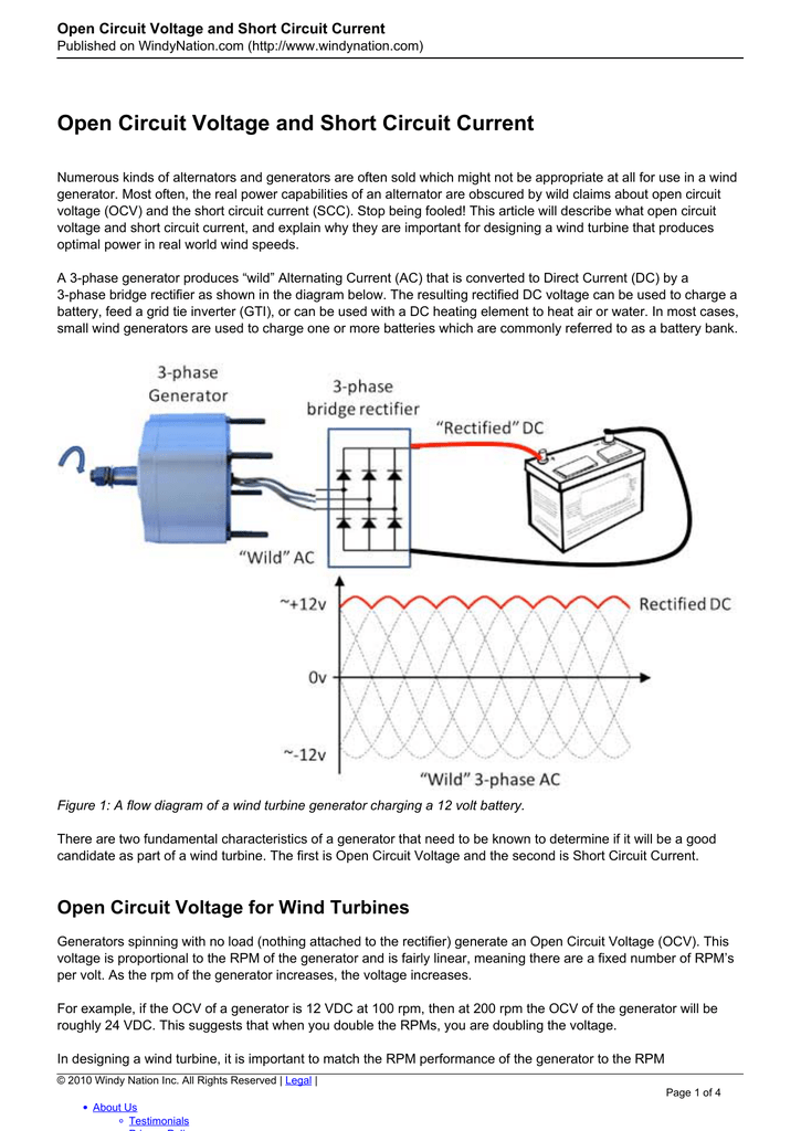
In generator, a three phase ac generator has three single phase windings spaced so that the voltage induced in each winding is 120° out of phase with the voltages in the other two windings.

News Info: How to build a 3 phase wind generator
Fast shipping asap is a generator parts supplier of many brands. Wiring diagram stamford generator. Design detail tdsx440gb050302 the main functions of the avr are. View and download winpower de20i4 installation and operation manual online. View and download stamford ac generators installation maintenance manual online.

Wind Turbine Generator 3 Phase Wiring Diagram - All of ...
Here we see a winding diagram for a 3-phase AC induction motor or brushless PM motor (IPM), having 4 poles and 36 slots. This winding could in fact be used with any AC machine, including a synchronous reluctance motor or a wound-field synchronous motor or generator. In most respects it is a regular classical example, and the objective here is to review some of the features of the diagram and ...

red Iron-Man hand keychain
01-12-2021 · Separate single-phase transformers can be used and externally interconnected to yield the same results as a 3-phase unit. Understanding Vector Group of Transformer (Part 1) The primary windings are connected in one of several ways.

Image from page 307 of "Cyclopedia of applied electricity : a general reference work on direct-current generators and motors, storage batteries, electrochemistry, welding, electric wiring, meters, electric lighting, electric railways, power stations, swit
Phasor diagram of a synchronous generator (similar to that of a transformer) Since the voltages in a synchronous generator are AC voltages, they are usually expressed as phasors. A vector plot of voltages and currents within one phase is called a phasor diagram. A phasor diagram of a synchronous generator with a unity power factor (resistive load)

Fuse Box And Wiring Diagram - Part 3
Single Phase Ac Generator Wiring Diagram from upload.wikimedia.org Print the electrical wiring diagram off and use highlighters to be able to trace the circuit. When you employ your finger or stick to the circuit together with your eyes, it is easy to mistrace the circuit. A single trick that I 2 to print the same wiring diagram off twice.

Motor winding diagram -- delta connection | Electrical ...
① Single phase kW/kVA ratings are approximately equal to 50% of the generator's three phase ratings. DELTA. Voltage. HZ. L-L. 60. 2402. 7967. 50.3 pages

Generator Winding How To Single Phase Generator Winding ...
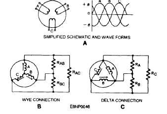
by A Bhatia · Cited by 5 — is identical to that used in the single-phase alternator. In the left-hand schematic, the rotor poles are opposite all the windings of phase A. Therefore, ...41 pages

woman in gray top
The alternating-current windings of two-phase alternating-current generators and synchronous motors shall have terminal markings as given in MG 1-2.66 for two-phase single-speed induction motors.* The alternating-current windings of single-phase alternating-current generators and synchronous motors

pink flamingo on green grass near lake during daytime
three-phase generator/alternator is simply three single phase machines interlaced with one another, sharing the same rotor assembly, with wiring brought out to connect each phase into the electrical system. The result of the interlacing of the alternator windings is shown on the voltage trace shown at the bottom of Figure 9-4.

Single phase motor winding|| Diagram|| winding pitch table ...
20-09-2015 · The element can be a generator, a motor, a static load, ... For an ideal single-phase two-winding transformer ... which name in English I don't know but translated from Spanish would be watch diagram (from diagrama de reloj). The phase shift \$ \delta \$ will always be a multiple of 30, ...

Regulation
The Double Delta connection is commonly used to utilise a 3-phase winding for a single phase output. This reconnection provides the possibility of a mix of 240V and 120V outputs simultaneously, but the current through the bottom leg when 240V and 120V are being taken, must not exceed the total current of 200A (48kVA / 240V). ...

Motor Rewinding Diagram Pdf | Webmotor.org
shaft of the single phase induction generator and generated 220V a.c. voltage for distributing electric load. The design of single phase induction generator is modified by rewiring the winding of an old 1 HP, 220 V, 50 Hz motor from 4 poles to 6 poles. For impulse turbine design, this paper use the information model from Baan Kiriwong

Engineering Photos,Videos and Articels (Engineering Search ...
Single Phase Outputs On some STAMFORD alternators, it is possible to reconnect a winding designed with 12 leads for a 3-phase output into a Double Delta configuration for a single phase output. Refer to the alternator's published technical data for the output kVA rating at a single phase voltage. More information is available in AGN154.

12 slot single phase generator rewinding diagram. rotor 10 ...

Three Phase Alternator Wiring Diagram - Database - Wiring ...
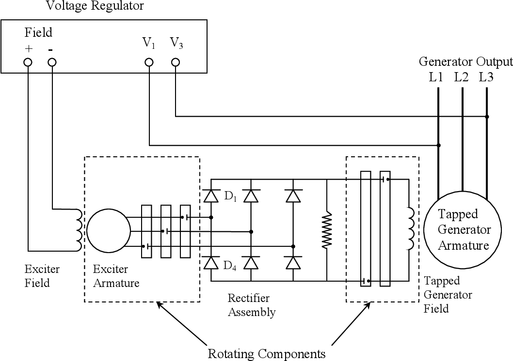
Figure 1 from Condition monitoring of brushless three ...

Single Phase Induction motor Winding Diagram | Electrical ...

Patent US7152301 - Method for winding a stator of multi ...

single phase grid conneced solar power & wind power ...
![[DIAGRAM] Single Phase Motor Winding Diagram FULL Version ...](http://singlephasepowersolutions.com/wp-content/uploads/2016/06/single-phase-motor.png)
[DIAGRAM] Single Phase Motor Winding Diagram FULL Version ...

Three Phase Winding Diagram 3000 rpm | Electrical Winding ...
AC Motor Winding | Generator Series Courseware | Pengky
3 Phase Alternating Current Pdf - lotbittorrent

3 phase motor as 1 phase generator diagram | Electric ...
What is a single phase power? - Quora

Patent US7075206 - Vehicle alternator stator winding ...
1 Cross-section of a 24-slot 4-pole outer stator with 3 ...
Comments
Post a Comment