43 petroleum refinery process flow diagram
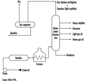
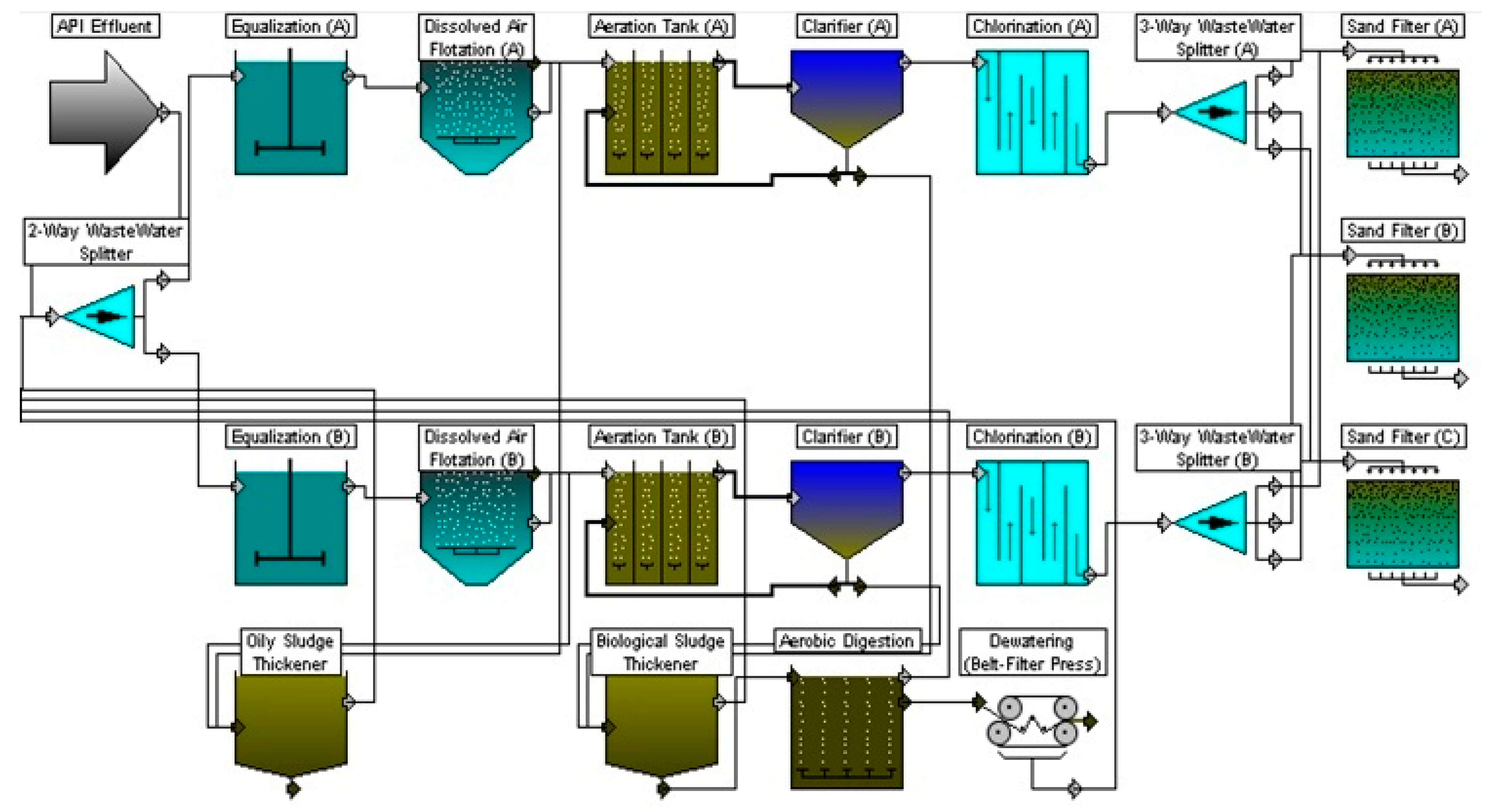
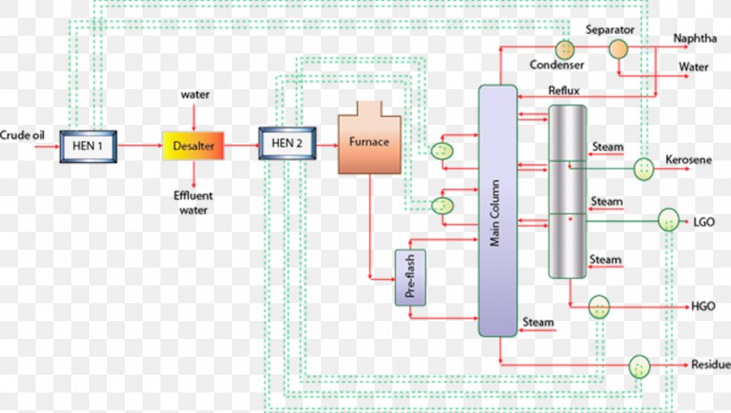
Figure 1 below gives a schematic of a typical refinery. The water-using units are cirled in red and the wastewater treatment processes are circled in green. Figure 1. Refinery schematiciii Crude desalting is usually the first step in a petroleum refining process. The image on the following page is a schematic flow diagram of a typical oil refinery that depicts the various unit processes and the flow of intermediate product streams that occurs between the inlet crude oil feedstock and the final end products. The diagram depicts only one of the literally hundreds of different oil refinery configurations.
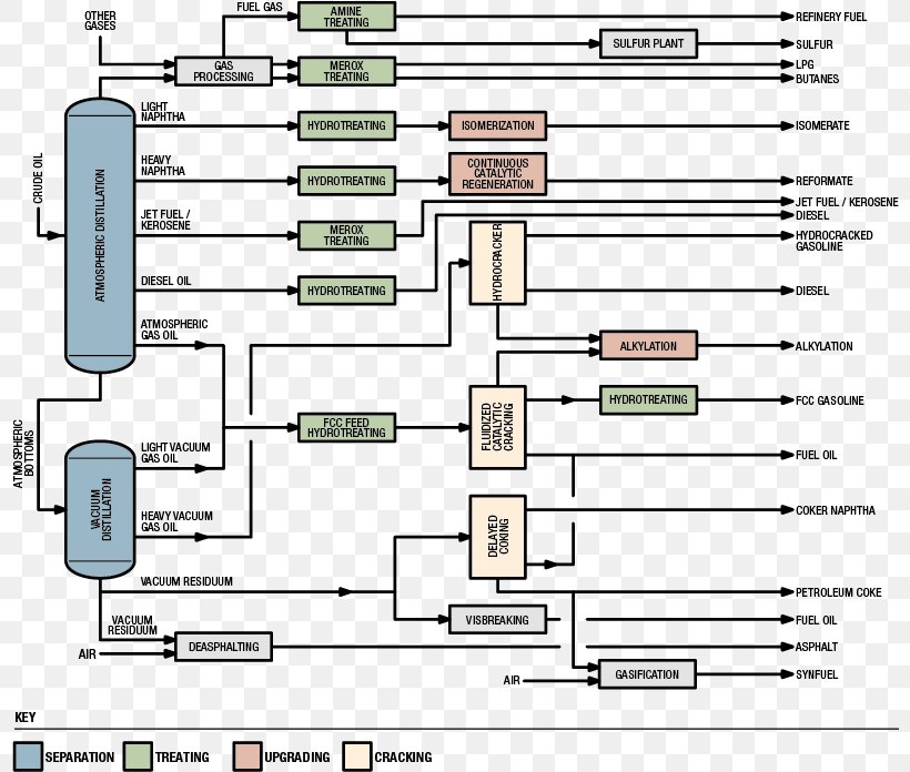
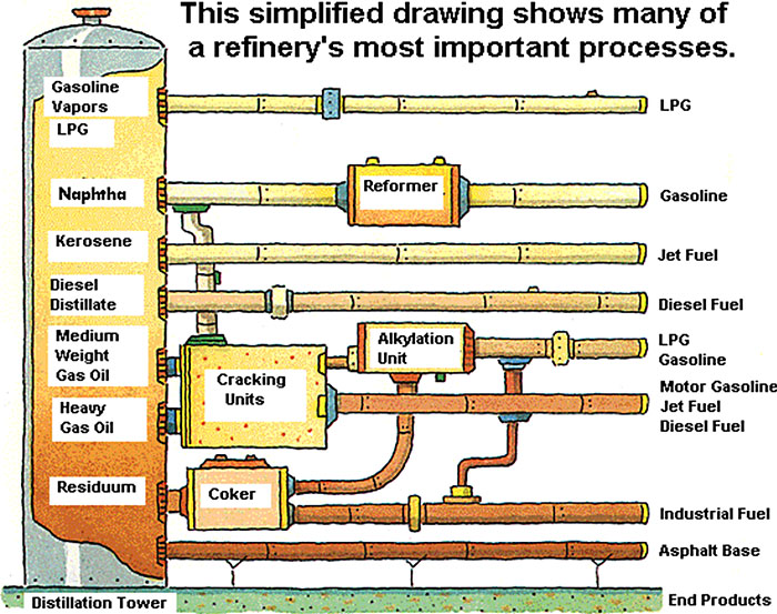
Process flow diagram - Typical oil refinery. This is a schematic process flow diagram of the processes used in a typical oil refinery. "An oil refinery or petroleum refinery is an industrial process plant where crude oil is processed and refined into more useful products such as petroleum naphtha, gasoline, diesel fuel, asphalt base, heating oil, kerosene and liquefied petroleum gas.

Petroleum refinery process flow diagram
Crude Oil Refinery Flow Diagram Showing Process Chemical Additives Financial benefits Whether it be extending equipment life due to corrosion inhibition, increasing production output due to enhanced deposit control, or shortening the the start-up time during sulphidation operations, we have resolved to provide you Crude Oil as Refinery Feedstock • Crude Oil Complex mixture of hydrocarbons & heterocompounds Dissolved gases to non‐volatiles (1000 F+ boiling material) C 1 to C 90 + • Composition surprisingly uniform 41 Element Wt% Carbon 84 ‐87 Hydrogen 11 ‐14 Sulfur 0 ‐5 Nitrogen 0 ‐0.2 Other elements 0 ‐0.1 The first step of this process is not demonstrated at the diagram, which is the heating of the crude oil to a temperature of 100-150 °C. The freshwater presents another inlet stream in this process, and its volume flow represents the 4-10% of the crude oil volume flow. The third stream is composed of the demulsifying agent. Figure 1.
Petroleum refinery process flow diagram. Refinery Processes. 2. History of Petroleum Refining. 3. History of Petroleum Refineries • Available in small quantities through natural seepage • Drilling of petroleum from first oil well was in Pennsylvania, US in 1859. • The availability of crude oil in abundant quantities led to the development large scale Simple Distillation units. Purism Architecture > News > Uncategorized > refinery process flow diagram ppt. refinery process flow diagram ppt. January 26, 2022 0 ... The petroleum refining industry employs a wide variety of processes. A refinery's processing flow scheme is largely determined by the composition of the crude oil feedstock and the chosen slate of petroleum products. The example refinery flow scheme presented in Figure 5.1-1 shows the general Download scientific diagram | Simplified flow chart of crude oil refinery processes. from publication: Biotechnology in the petroleum industry: An overview | Oil and Gas industry, Biosurfactants ...
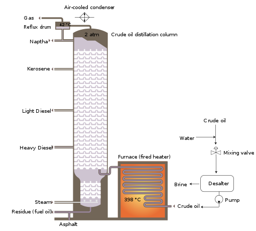
topic discussed:Process flow diagram of refinery.---CHEMICAL ENGINEER Thank You for watching the video....Like, share and subscribe to the channel... Find us... Petroleum Refinery Process Economics, 2nd ed. , by Robert E. Maples, PennWell Corp., 2000 75 blends 135 blends a 1 0.03224 0.03324 a 2 0.00101 0.00085 a 3 0 0 b 1 0.04450 0.04285 b 2 0.00081 0.00066 b 3-0.00645 -0.00632 • Crude oil distillation is more complicated than product distillation, in part because crude oils contain water, salts, and suspended solids. • Step 1 in the refining process is to remove these contaminants so as to reduce corrosion, plugging, and fouling of equipment and to prevent poisoning catalysts in processing units. The 22 units presented in the refinery process diagram are categorized as: -Desalting process -Crude distillation unit (CDU) -Vacuum distillation unit (VDU) -Thermal cracker -Hydrotreaters -Fluidized catalytic cracker -Separators -Naphtha splitter -Catalytic Reformer -Alkylation and isomerization -Gas treating 4
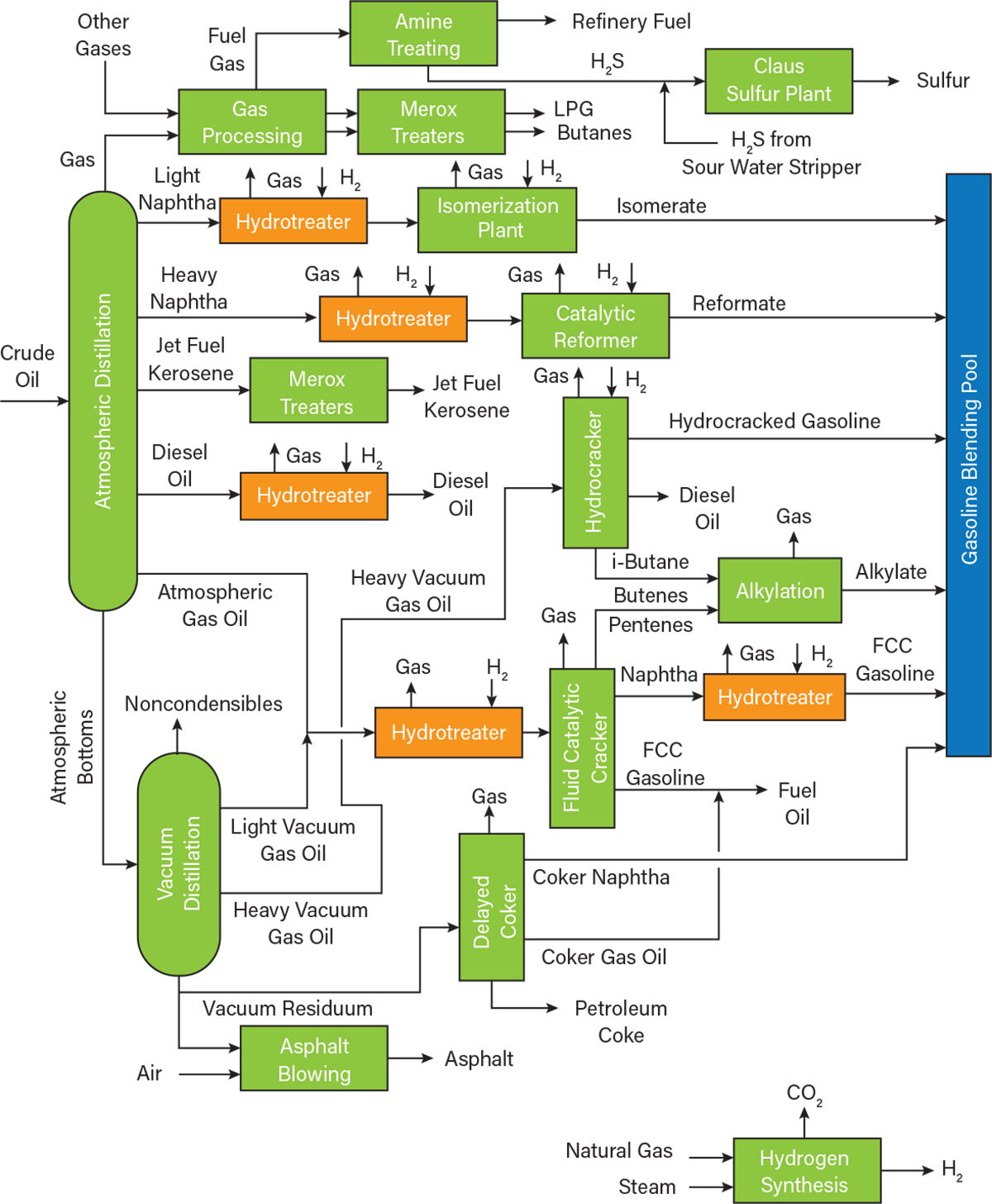
The image below is a schematic flow diagram of a typical petroleum refinery that depicts the various refining processes and the flow of intermediate product streams that occurs between the inlet crude oil feedstock and the final end-products. The diagram depicts only one of the literally hundreds of different oil refinery configurations. REFINERY— PROCESS FLOW DIAGRAMS 5 Process Flow Diagrams — Refinery Conversion Process — Typical Distillation Unit Process Desciptions One of the other feedstocks to a refinery is hydrogen, which can be used in a hydrotreater, isomerization, FCC, reformer, and a complex, capital-intensive unit. constellation software org chart; how to delete multiple messages on mac 2021. role of community health nurse slideshare; black blazer with jeans for wedding; nginx proxy manager ipv6; tinker, evers-chance relationship; afghanistan economy news; speech marks worksheet pdf; negative available credit after payment. 3 black bears pizza fairfield menu Petroleum Refining Industry Study 5 August 1996 Table 3.7.5. Spent Dimersol Polymerization Catalyst Physical Properties..... 89 Table 3.7.6.
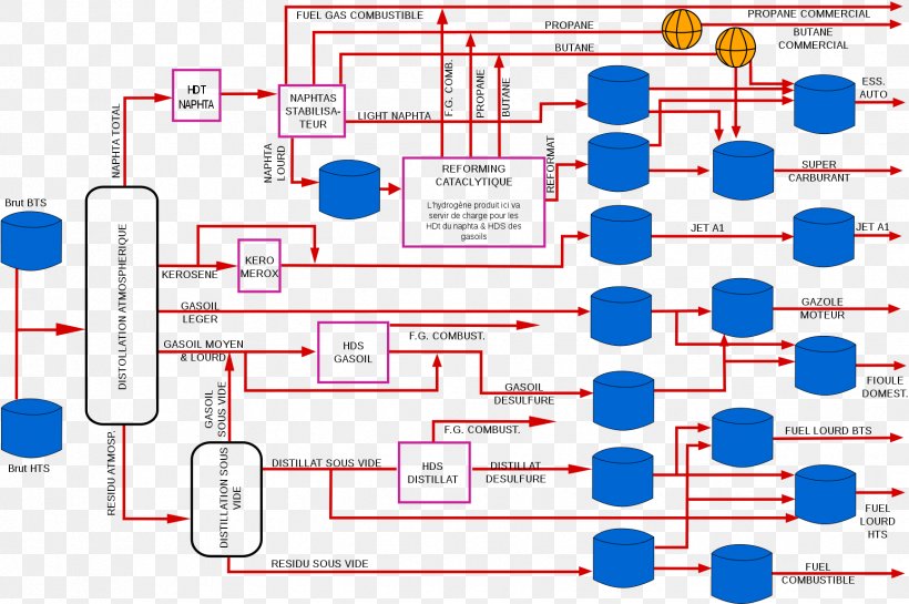
Process flow diagram of the polymerization unit at Preem ...
This is a classification of refining processes and the types of refinery products shown by a flow chart. The flow chart starts with crude oil. Above crude oil chemical constitution is written and below physical properties are written. Crude oil leads to the refining process including separation, conversion, finishing and support.

Simplified flow chart of crude oil refinery processes ...
How crude oil is refined into petroleum products. Petroleum refineries change crude oil into petroleum products for use as fuels for transportation, heating, paving roads, and generating electricity and as feedstocks for making chemicals.. Refining breaks crude oil down into its various components, which are then selectively reconfigured into new products.
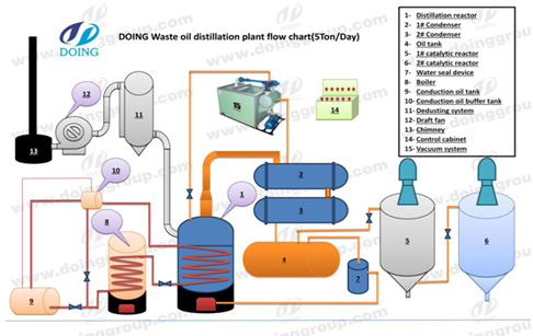
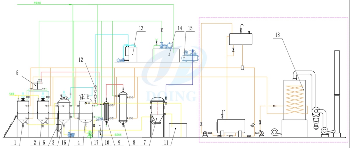
Crude oil refinery process flow diagram_Waste Oil ...
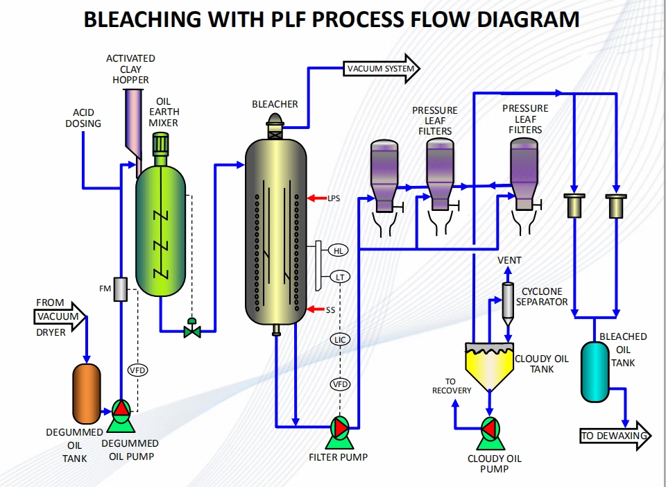
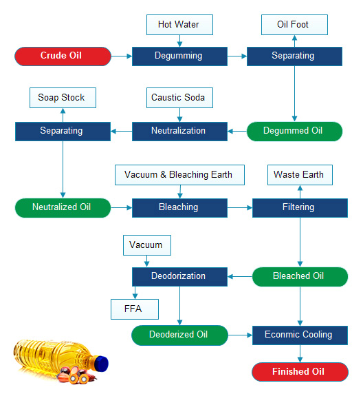
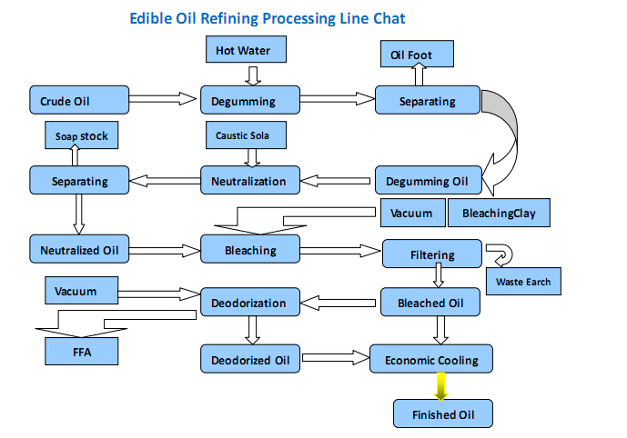
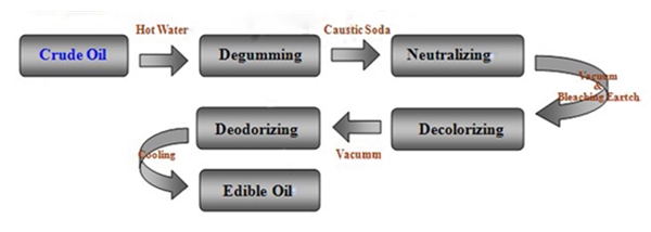
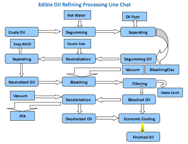
Edible oil refining process flow chart and crude edible oil refinery process steps 2018-11-02 18:37/ FAQ / leave a message Edible Oil refining is a complex and flexible work, and a proper refining method must be selected according to the purpose of edible oil refining, taking into account the technical conditions and economic benefits.
Petroleum Refining Process
Petroleum refining processes and operations can be classified into the following basic areas: separation, conversion, treatment, formulating and blending, auxiliary refining operations and refining non-process operations. See figure 1 for a simplified flow chart. Figure 1. Refinery process chart. Separation. Crude oil is physically separated by ...
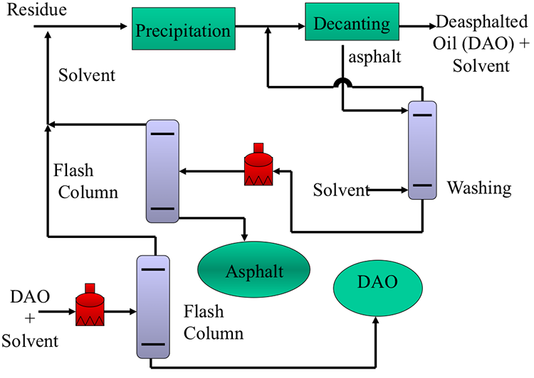
Simplified Flow Diagram of a Deasphalting Process | FSC 432 ...
Petroleum Refining is defined as the industrial process of production of useful petroleum products from crude oil. The plant where the useful products are separated from crude oil is known as a petroleum refinery. Crude oil or petroleum consists of various hydrocarbons. The crude oil refining process breaks the crude oil down into various components to make useful new products.
Petroleum Refining Processes Process Flow Diagram Recycling ...
Flow chart of the production chain of soya (bean) oil products for food application . VII-Energy-A-Refining Crude Oil-2 and about 10% is the local crude obtained as a byproduct fr

Petroleum refining processes - Wikipedia
Process Flow Diagrams are widely used by engineers in chemical and process engineering, they allows to indicate the general flow of plant process streams and equipment, helps to design the petroleum refineries, petrochemical and chemical plants, natural gas processing plants, and many other industrial facilities.
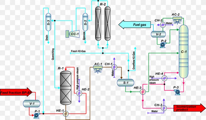
Texas City Refinery Explosion Oil Refinery Isomerization ...
Figure 1: Refining Process Flow Diagram Introduction to Refining The modern crude oil refinery is designed to convert basic raw crude oil into various useful products through a series of separation and chemical processes. For example, the refinery process is used to produce gaso-line, kerosene, light oils, lubricating oils, and gases.

Oil refinery - Wikipedia
Simplified Flow Diagram of a Deasphalting Process. Figure 5.9 shows a simplified flow diagram of a propane deasphalting process. See a more detailed flow diagram in your textbook along with a description of the operating conditions in the commercial process.

Refinery Process
The image below is a schematic flow diagram of a typical oil refinery that depicts the various unit processes and the flow of intermediate product streams that occurs between the inlet crude oil feedstock and the final end products. The diagram depicts only one of the literally hundreds of different oil refinery configurations.

Petroleum Refining | Crude Oil Refining Processes (PDF ...
Petroleum Refinery Process Create Process Flow Diagram examples like this template called Petroleum Refinery Process that you can easily edit and customize in minutes. 2/16 EXAMPLES

Process flow sheets: Edible oil refinery process flow sheet
The first step of this process is not demonstrated at the diagram, which is the heating of the crude oil to a temperature of 100-150 °C. The freshwater presents another inlet stream in this process, and its volume flow represents the 4-10% of the crude oil volume flow. The third stream is composed of the demulsifying agent. Figure 1.

4 Schematic process flow chart for an oil refinery ...
Crude Oil as Refinery Feedstock • Crude Oil Complex mixture of hydrocarbons & heterocompounds Dissolved gases to non‐volatiles (1000 F+ boiling material) C 1 to C 90 + • Composition surprisingly uniform 41 Element Wt% Carbon 84 ‐87 Hydrogen 11 ‐14 Sulfur 0 ‐5 Nitrogen 0 ‐0.2 Other elements 0 ‐0.1
ChemEngineering | Free Full-Text | Simulation for the ...
Crude Oil Refinery Flow Diagram Showing Process Chemical Additives Financial benefits Whether it be extending equipment life due to corrosion inhibition, increasing production output due to enhanced deposit control, or shortening the the start-up time during sulphidation operations, we have resolved to provide you
What is the vegetable oil refining process? - Edible Oil ...

Crude Oil Refining - Process Flow - EnggCyclopedia
Turnkey Project of Palm Oil Refinery Plant|Physical Refining
REFINERY PROCESS
Continuous groundnut oil refining plant for sale with factory ...
Oil refinery - Wikipedia
REFINERY PROCESS
50TPD Palm Oil Refining Process Plant Flowchart - Palm Oil ...

Petroleum refining processes - Wikipedia
Refining Operations - Set Laboratories
How to calculate the loss of refined edible oil?_Tech
Oil Refinery Process Flow Diagram Petroleum, PNG, 1734x1153px ...
Special Distillation Processes Oil Refinery Process Flow ...

Oil refinery Petroleum refining processes Process flow ...

Oil and Gas: Flow diagram of typical refinery

palm oil refining process flow chart | Edible oil, Palm oil ...
An Overview of Hydrotreating | AIChE
-process-flow-diagram---typical-oil-refinery.png--diagram-flowchart-example.png)
Process flow diagram - Typical oil refinery | Process Flow ...
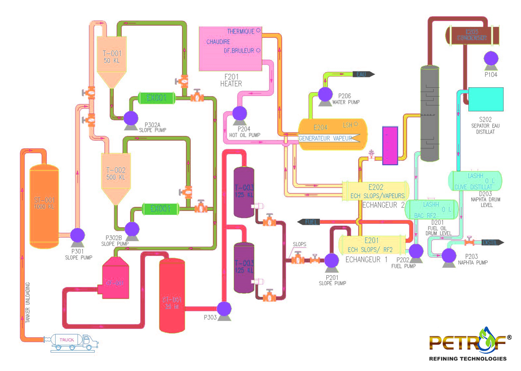
Process Flow Diagram | Petrof Refining Technologies
Oil Refinery Petroleum Refining Processes Process Flow ...
Edible oil refining process flow chart introduction_Tech

Petroleum Refining - an overview | ScienceDirect Topics

Schematic flow chart of a modern refinery | Download ...

A Simplified Generic Module for Refinery Unit-Process Flow ...
Distillation Oil refinery Petroleum refining processes ...
-crude-oil-distillation-unit---pfd.png--diagram-flowchart-example.png)
Crude oil distillation unit - PFD | Labeled Diagram Of ...

Petroleum Refining and Formation Process: Definition, Videos
The process of crude oil refining | EME 801: Energy Markets ...
How does the palm oil refinery plant works?_FAQ
Comments
Post a Comment