43 hydraulic valve body diagram
Sonnax valve body layouts provide a detailed overview of individual units making it quick and easy to determine what's available for the specific valve body you're working on. Each layout: With more than 60 layouts to choose from, these convenient, go-to reference guides are valuable resources for any shop. View, download or print these ... A 2/2 valve has two states (open/close) and is therefore represented by two adjacent squares. In each square is shown how the medium can flow between the ports. This is done with arrows, that indicate which ports are connected and what is the flow direction. Closed ports are indicated by a 'T'. To indicate which square is active when the solenoid is electrically energized, a little …
Parker offers a wide range of hydraulic valves for a variety of mobile and industrial applications. We manufacture all types of hydraulic valves: from directional control valves to pressure control, flow control, shuttle, sequence, high pressure non-return and ball valves, from monoblock and sectional to manifold mounted, in-line and slip-in cartridge valves, from standard on/off valves to ...
Hydraulic valve body diagram
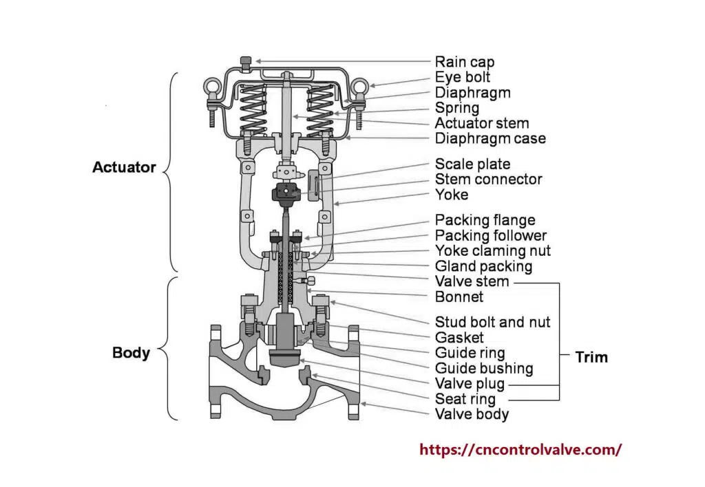
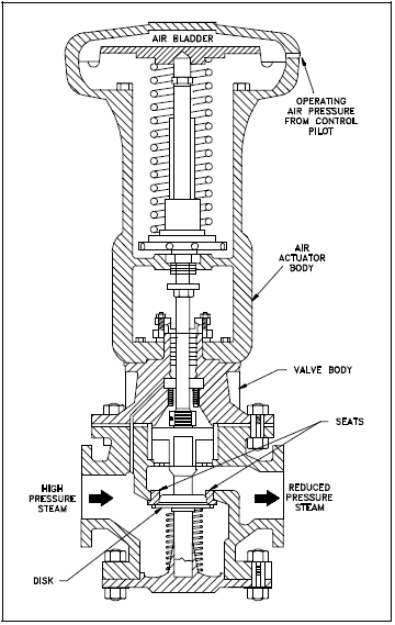
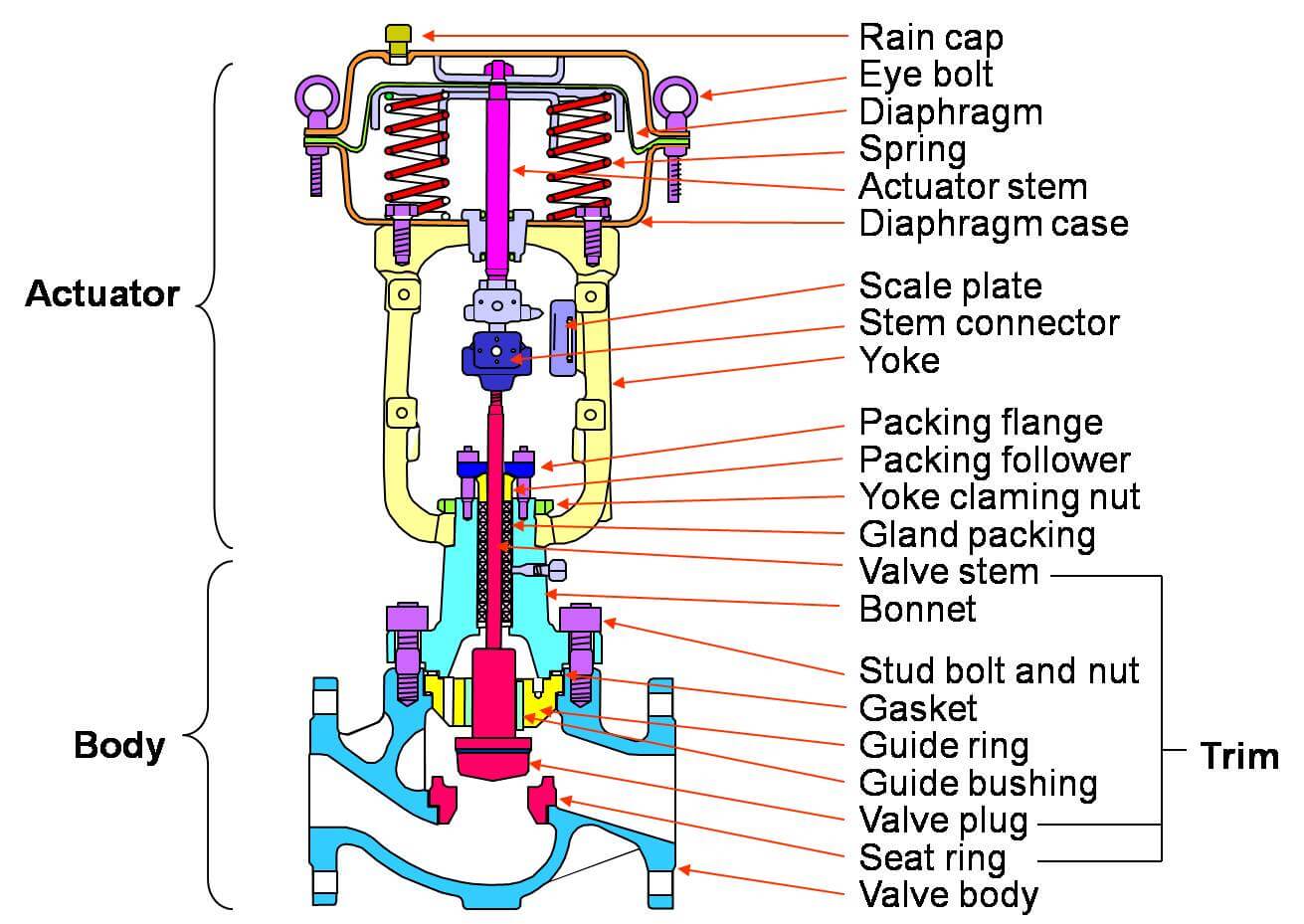
The valve's body is the outer casing of most or all of the valve that contains the internal parts or trim. ... Pneumatic actuators and hydraulic actuators need pressurised air or liquid lines to supply the actuator: an inlet line and an outlet line. Pilot valves are valves which are used to control other valves. Pilot valves in the actuator lines control the supply of air or liquid going to ... 01.07.2018 · 3 SPOOL 25 GPM PRINCE JOYSTICK VALVE W/GRAPPLE CONTROL Brand new PRINCE. Three spool joystick valve for operating double acting cylinders with first spool float and third spool single lever to operate a double acting grapple cylinder. Features include monoblock gray cast iron body, hard chrome plated spools, load checks and spring centering ... 7. The valve is reassembled by following the same directions in reverse. The o-ring and spool must be lubricated with oil before installation. 7/7 Code Part No. Hydraulic scheme A 414.01.00.08 M 414.01.00.10 POS. # PART # DESCRIPTION QTY. 1 414.00.00.04 VALVE BODY 1 2 DIN 3771 O-RING 18x4 1 3 414.01.00.01 STOP CUP 1 4 414.01.00.05 WASHER 1
Hydraulic valve body diagram. Servo valves are a close relative of the proportional valve and are based on an electrical torque motor which produces a small deflection proportional to the electrical current through its coil. They commonly use feedback between the main and pilot spools to give precise control. A typical device is shown in Figure 4.40.This consists of a small pilot spool connected directly to the … Circuit diagram. Hydraulic system circuit diagram represented by professional graphic symbols. Hydraulic drive system. The hydraulic transmission device is a device that converts pressure of fluid into power. Hydraulic pressure station. A hydraulic device consisting of a fuel tank, a hydraulic pump, a motor, a control valve, etc. Hydraulic balance 4r100 Transmission Valve Body Diagram. Since the introduction of the 4R transmission in model year , there have been many engineering .. 4R VALVE BODY CHECKBALL LOCATIONS Partial Hydraulic Schematic is provided for you in Figure 40 on Page Moving BS6 to the lower valve body put it near the SS2 (shift solenoid 2) circuit, on models that use it ... A simple hydraulic schematic showing apparatus for testing the strength of a hydraulic hose splice. Water enters through normally closed solenoid valve (1) and passes through intake flow meter (2) to high pressure pump (4). Intake water pressure is monitored by pressure gauge (3).
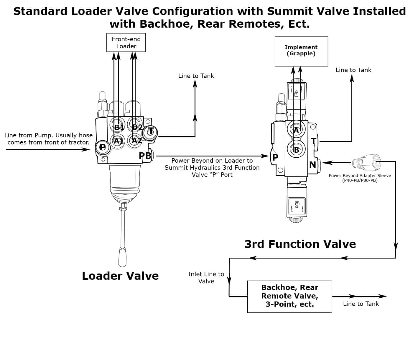
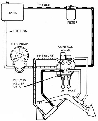
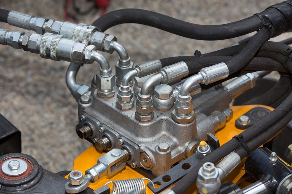
valve body contains the internal porting to direct the fluid flow. The outer ports on the valve block are threaded to allow hoses and lines to be connected to it. Solenoid Valve The solenoid valves consist of the valve cartridge and the solenoid coil. To disassemble the valve remove the coil assembly and then carefully unscrew the valve body. The O-rings and seals should be … X. 4R VALVE BODY CHECKBALL LOCATIONS. REQUIRES TWO ATSG. Partial Hydraulic Schematic is provided for you in Figure 40 on Page This manual covers Principles of Operation, Complete hydraulic circuit diagrams, Valve Body Mapping (passage identification for the valve body and all spacer plates). It also includes a complete exploded view of the ... Hydraulic Valve Division EZ Reference Guide Catalog. Table of Contents Assembled Valves. VA 20 NPT Ports 10 Digit Code Page. 3 Way 3 Position Manual 347-9201-816 5. 4 Way 3 Position Manual 347-9201-817 6. 3 Way 3 Position Pneumatic 347-9201-823 7. 4 Way 3 Position Pneumatic 347-9201-818 8. Hydraulics Systems Diagrams and Formulas Loader The above system shows a front end loader powered by a PTO driven pump. A 2-spool directional control valve with built-in relief controls the lift and bucket cylinders of the loader. A return line filter is used to prevent contamination. Winch The diagram shows a winch powered by a hydraulic motor.
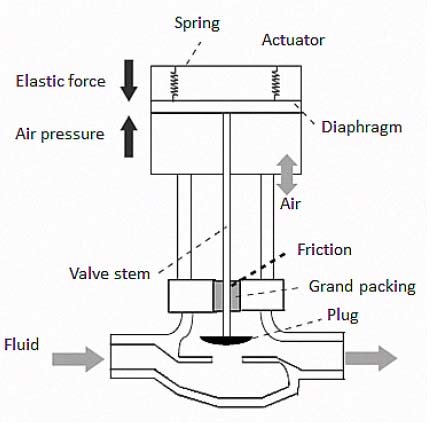
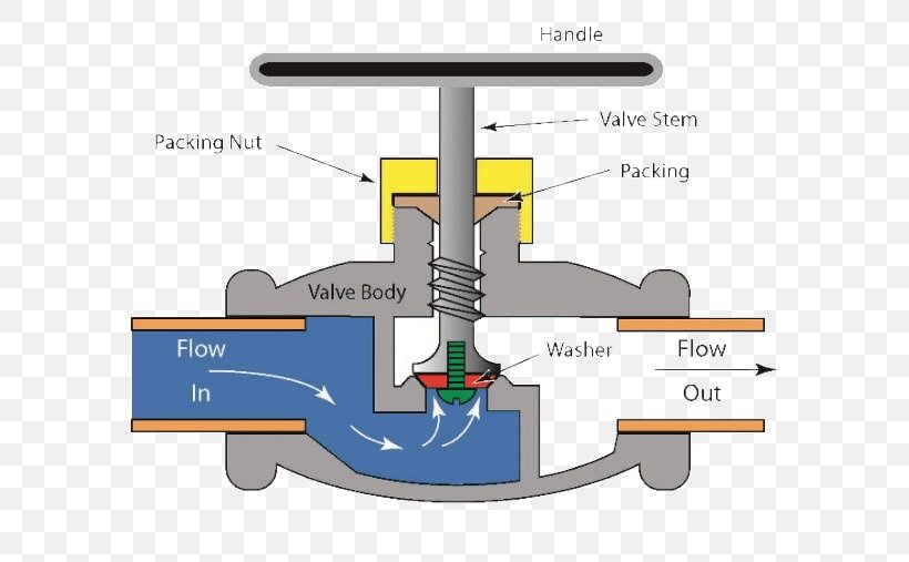
The main components of a butterfly valve are the body, seal, disc and stem (Figure 2). A typical butterfly valve has the disc positioned in the center of the connected pipe and a stem that is connected to an actuator or handle on the outside of the valve. In the closed position, the disc is perpendicular to the flow, as shown in Figure 2, and is sealed by the valve seat. The stem is … A hydraulic brake is an arrangement of braking mechanism which uses brake fluid, typically containing glycol ethers or diethylene glycol, to transfer pressure from the controlling mechanism to the braking mechanism. History. During 1904, Frederick George Heath (Heath Hydraulic Brake Co., Ltd.), Redditch, England devised and fitted a hydraulic (water/glycerine) brake … A method of modifying a transmission valve body, the valve body including: an . Each of the 46RE, 47RE, and 48RE transmissions have four gears (the 13 is a hydraulic circuit diagram of a portion of the 46RE and 47RE.Nov 17, · Valve body with filter still in place The instructions that come with the valve body are pretty good. Some valves are provided with actuators to allow remote operation, to increase mechanical advantage, or both. Figure 2 shows the symbols for the common valve actuators. Note that although each is shown attached to a gate valve, an actuator can be attached to any type of valve body. If no actuator is shown on a valve symbol, it may
6 Main Performance Characteristics Of The Pneumatic Diaphragm ...
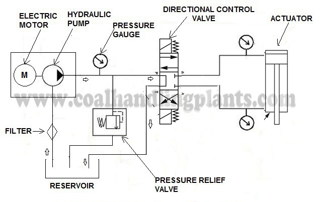
All hydraulic applications are based on flow and pressure requirements. Flow, expressed in gallons per minute (GPM), determines the speed at which a hydraulic cylinder extends or a hydraulic motor turns. Flow is produced by the pump. Pressure, expressed in pounds per square inch (PSI), determines the amount of force exerted.
Honda CR-V - Hydraulic Controls - System Description
1. Remove all parts from both ends of valve. 2. Remove valve spool from valve body and remove seal retainer, back-up washer, O-ring at each end of valve body. 3. Replace valve spool into housing. 4. Install new O-ring seal, back-up washer, and old seal retainer in each end of valve body. 5. Reassemble per pictorial of valve and parts list.

Hydraulic Solenoid Valve - How They Work | Tameson.com
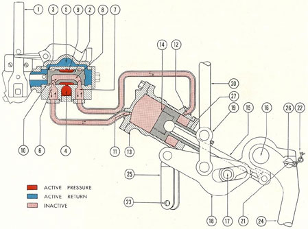
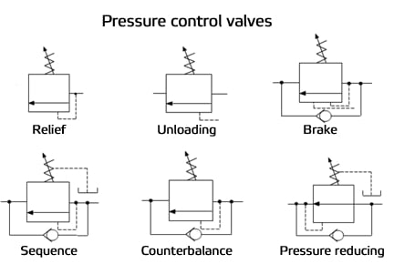
a hydraulic circuit or to provide a free flow path around a restrictive valve. OPERATION - Pressure on the inlet (port 1) of the check valve creates a force against the poppet, pushing it off its seat and permitting free flow to port 2.
Mazda 6 Service Manual - Control valve body installation ...
except where noted, the prestolite motors come without a hydraulic valve body. if you have a hydraulic valve body problem, you may replace it with one of these new valve bodies to replace the 112 and 116 prestolite units. no core is required to purchase these hydraulic units. vb112n-4 fits chrysler/force; o-ring included.

Hydraulic Spool Valve Diagram | Hydraulic Valves Spool Diagram
VALVE DESCRIPTION (VICTOR) The hydraulic control valves are made up of one or two spool valves and a cast iron valve body. Normal working pressure is 500-700 PSI. An imple- ment relief valve is part of the control valve and is factory set at 700 PSI - do not attempt to alter this setting. Severe transmission damage may result.

Log Splitter Valve and Accessories by Energy® Manufacturing ...
They're simple, compact and heavy duty designed, with cast iron body and steel spool. Available from 2--way to 10--way, diverter valves are suitable to intercept and divert the flow on hydraulic systems, wherever movement sequence or control selection of different actuators is needed. Diverter valves DGR002A 3

Basic Hydraulics - Directional Control Valve - Blog.Teknisi
4l60e Accumulator Diagram. While the 4L60e is open, I am replacing the Accumulator to the Sonnax Pinless just to make sure I don't have issues with my car down the road. The 4L60e. that release pressure and the accumulator spring returns the piston back in its bore. A hydraulic diagram of each shift will be the key to knowing this answer.

Four-port three-position directional control valve - MATLAB
Keep your transmission shifting smoothly with hydraulic valve body parts. Shop filters, valves, gaskets, pressure gauges and more at Zip's AW Direct. 800-222-6047
Submarine Hydraulic Systems - Chapter 3
In fluid power systems it is common for a valve to have three to eight pipes attached to the valve body, with the valve being capable of routing the fluid, or several separate fluids, in any number of combinations of input and output flowpaths. The symbols used to represent fluid power valves must contain much more information than the standard P&ID valve symbology. To meet this …
Electric Hydraulic Double Acting Directional Control Valve, 3 Spool, 25
HYDRAULIC PUMPS 6-9 HYDRAULIC VALVES HYDRAULIC HOSES HYDRAULIC FITTINGS 3 4 5 HYDRAULIC RESERVOIR TANKS 10 POWER TAKE OFF (PTO) 11-12 WET KIT SYSTEMS 13-16 WET KIT ( DUMP TRAILER) QUOTE / ORDER SHEET 17. 8-5-265 Super Dump 73-40-110 SAT Hoist 7-3-120 SAT Hoist Hydraulic Operated Tailgate Lift Cylinder
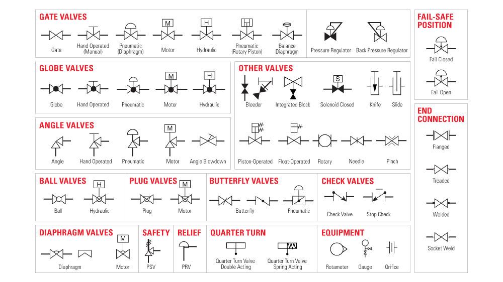
The Most Common Control Valve Symbols on a P&ID | Kimray
Summery. In this article, we have learned that spool valves are a common way of controlling hydraulic or pneumatic components by allowing, restricting or blocking the flow of the energy source by way of a simple spool mounted within an outer casing. We have learned that energy sources and components are connected to the spool valve using ports ...
DIRECTIONAL CONTROL VALVES VINCKE
Parker offers the largest selection of hydraulic directional control valves, known for their performance and reliability. This video will show you how to tear down and rebuild Parker's D1VW directional control valves. Improve efficiency, increase safety and reduce downtime with Parker's directional control valves. Click Here to See the Video.
Working Principle of Control Valve + Diagram | Linquip
Hydraulic Spool Valve Diagram Introduction: E -Type Features: In the neutral position , all oil ports closed, not flow . Functional characteristics: 1. The inlet and outlet ports of device are closed, hydraulic actuator can be fixed in any its' working mechanism position, and no movement or rotary further even if there is external force on it ...
Reading fluids circuit diagrams - hydraulic & pneumatic symbols
About Press Copyright Contact us Creators Advertise Developers Terms Privacy Policy & Safety How YouTube works Test new features Press Copyright Contact us Creators ...

Learn About Steam | Control Valves | Spirax Sarco
Vevor Hydraulic Directional Control Valve Log Splitter Nptf Ports 1... $78.99 USD. No reviews No questions. Quick View. VEVOR. 3 Spool 11gpm Hydraulic Directional Control Valve Double Acting 11 Gpm. $82.99 USD. 1 review.
Valves | Engineering Library
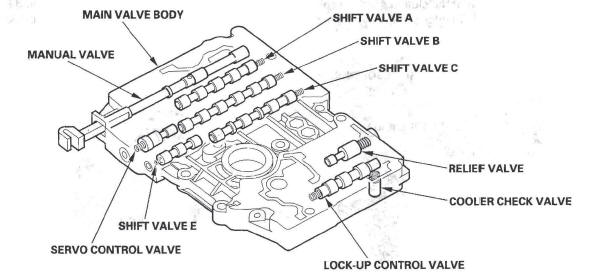
The valve body is one of the pieces of equipment that allows an automatic transmission to function correctly. By channeling hydraulic fluid through a series of paths, the valve body is able to trigger the correct clutch pack for the selected gearing. Inside of the valve body, there are a number of valves, each of which is referred to by the ...
Globe Valve Ball Valve Gate Valve Flow Control Valve, PNG ...
Parts Diagrams. Steel Parts Diagram 1 - L Boom 2 - Boom Head Reciever 3 - Boom Head Swivel 4 - King Pin Bolts 5 - Jaw Pin Bolt 6 - Passenger Side L Arm 7 - Up/ Down Cylinder Pin 8 - Stick 9 - Upper Fold Cylinder Pin 10 - King Pin 11- Jaw Pin 12 - Stick Pin 13 - Fold Cylinder Lower Pin 14- Fold Pin 15 - Drawbar 16- Driver Side L Arm 17 - Rear ...

Spool Valve - an overview | ScienceDirect Topics
I replaced the o rings in the valve body of the 460 hydraulic system but the leak continues. I took the return pipe between the body and the transmission to see if it was draining back OK.. The fluid was just setting there at about the top of the transmission level and did not drain down. It seem...
Basic Hydraulic System - Components / Parts,Design & Circuit ...
13.10.2019 · If you would like to describe the hydraulic valve or hydraulic control valve in one sentence, we would like to say that: – The hydraulic valve actually, is a device that can change the opening degree of liquid (Oil) flow path Only to understand the meaning of this sentence totally will comprehend the effects and phenomena of hydraulic valves in the actual hydraulic …

Schematic showing the contact between a valve spool and a ...
7. The valve is reassembled by following the same directions in reverse. The o-ring and spool must be lubricated with oil before installation. 7/7 Code Part No. Hydraulic scheme A 414.01.00.08 M 414.01.00.10 POS. # PART # DESCRIPTION QTY. 1 414.00.00.04 VALVE BODY 1 2 DIN 3771 O-RING 18x4 1 3 414.01.00.01 STOP CUP 1 4 414.01.00.05 WASHER 1
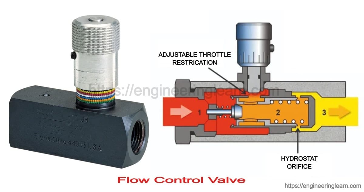
Flow Control Valve: Definition, Types, Components & Working ...
01.07.2018 · 3 SPOOL 25 GPM PRINCE JOYSTICK VALVE W/GRAPPLE CONTROL Brand new PRINCE. Three spool joystick valve for operating double acting cylinders with first spool float and third spool single lever to operate a double acting grapple cylinder. Features include monoblock gray cast iron body, hard chrome plated spools, load checks and spring centering ...

Basic Parts of Control Valve - Control Valves - Engineers ...
The valve's body is the outer casing of most or all of the valve that contains the internal parts or trim. ... Pneumatic actuators and hydraulic actuators need pressurised air or liquid lines to supply the actuator: an inlet line and an outlet line. Pilot valves are valves which are used to control other valves. Pilot valves in the actuator lines control the supply of air or liquid going to ...

valve body, valves - Excavators Volvo EC340 - Hydraulic ...
HYDRAULIC SYSTEMS
Basic Parts of Control Valves - Control Valve Functions

Sonnax Valve Body Inspection & Reaming for Repair

Monoblock Hydraulic Directional Control Valve, 2 Spool, 11 GPM

How Directional Valves Affect Oil Flow in Hydraulic Systems
Basics of Control Valves and Parts of Control Valve - Valves ...

Sliding-stem Valves | Basic Principles of Control Valves and ...

Directional spool valve 1 Drawing: valve body + spool ...
Control Valve with Wide Flow Range -

Shift Valves
Hydraulics Systems Diagrams and Formulas | Cross Mfg.

What is a spool valve? What are the types of the spool valve ...
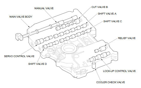
A/T System Description - Hydraulic Controls (A/T ...

Spool Valve - an overview | ScienceDirect Topics
![CONTROL VALVE BODY INSTALLATION [SJ6A-EL] | 2016 ND Shop Manual](https://www.hexorcism.com/16ND/wp-content/uploads/2017/05/AMXUUW00003563.GIF)
CONTROL VALVE BODY INSTALLATION [SJ6A-EL] | 2016 ND Shop Manual

Control Valve Actuators: Basic Types and Designs ~ Learning ...
Valve body Diagram w202 c280 96' | Mercedes-Benz Forum
About Hydraulic Valves

CHAPTER 10: Directional Control Valves, part 4 | Power & Motion
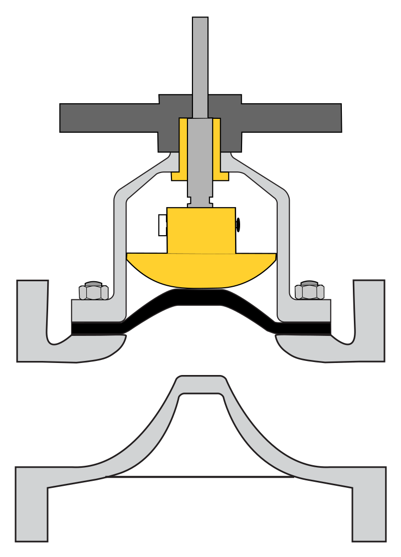
Diaphragm valve - Wikipedia
Comments
Post a Comment