43 the engager breakaway system wiring diagram
Hopkins offers a variety of towing solutions including vehicle wiring kits, adapters, vehicle and trailer connectors, breakaway systems and much more. Today, more than 40 percentage of retail category sales are generated from Hopkins innovations. The Hopkins Engager Break Away System changes the way you protect your trailer investment. Break away hopkins breakaway system electric brake caravan trailer the engager b. Wiring diagram to install hopkins proportional brake controller in a 2010 chevy silverado 1500. To hunt for wiring diagrams or making numerous unnecessary connections. I am purchasing a camper and i need to get my dodge ram if you are not installing a brake ...
Diagram showing which color wire to use. Basic 12 Volt Wiring . Diagram showing which color wire to use. Basic 12 Volt Wiring - installing LED light fixture...Epicord 30amp RV Power Inlet Receptacle 125V Marine Shore Twist Lock Power Inlet for Camper RV, Straight Blade Nema L5. Example Wiring Diagram for Multiple Battery Cutoff Switches …

The engager breakaway system wiring diagram
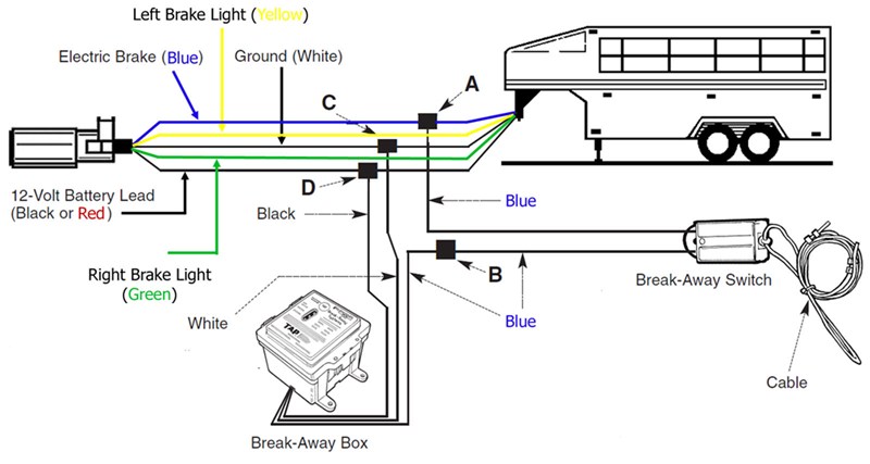
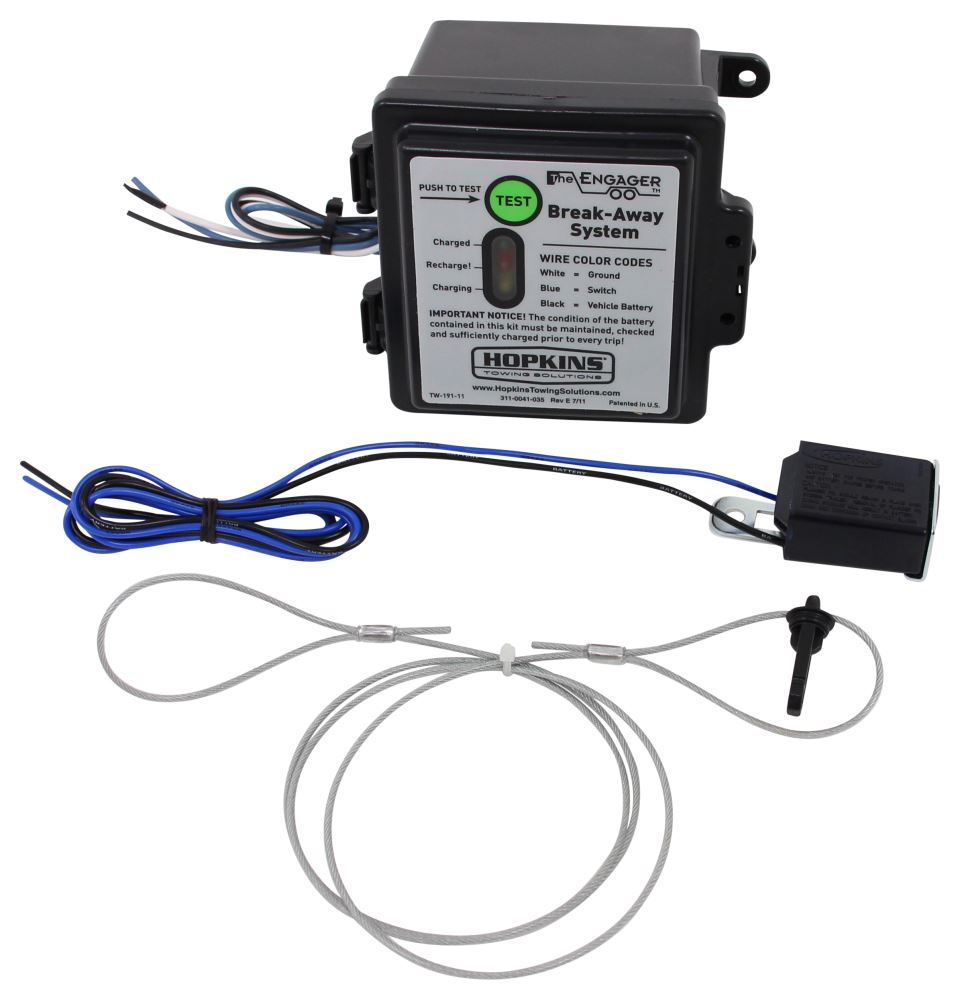
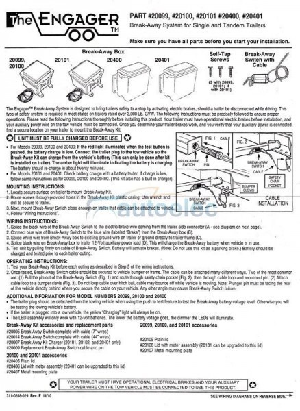
Jun 20, 2019 · The Engager Breakaway System Wiring Diagram – wiring diagram is a simplified customary pictorial representation of an electrical circuit. It shows the components of the circuit as simplified shapes, and the talent and signal friends amid the devices. Jan 12, 2018 · Follow "Wiring Instructions". WIRING INSTRUCTIONS: BREAK-AWAY SWITCH FIG. 2 BREAK-AWAY SWITCH SAFETY CHAIN POCKET BUMPER CLEVIS FIG.I CABLE PIN BREAK-AWAY SWITCH FIG. 3 CABLE INSTALLATION 1. Splice one blue wire of the Break-Away Switch to the electric brake wire coming from the trailer side connector (A - see diagram on next page). 2. The Engager is designed to activate the trailer brakes in the event the trailer is separated from the towing vehicle. Trailer break-away kits are legally ... Break-Away Box: SEE WIRING DIAGRAMS ON REVERSE SIDE ... Screws 20400, 20401 (3 with 20099, 4 with 20400) The Engager™ Break-Away System is designed to bring trailers safely to a stop by activating electric brakes, should a trailer be disconnected while driving. This type of safety system is required in most states on trailers rated over ...
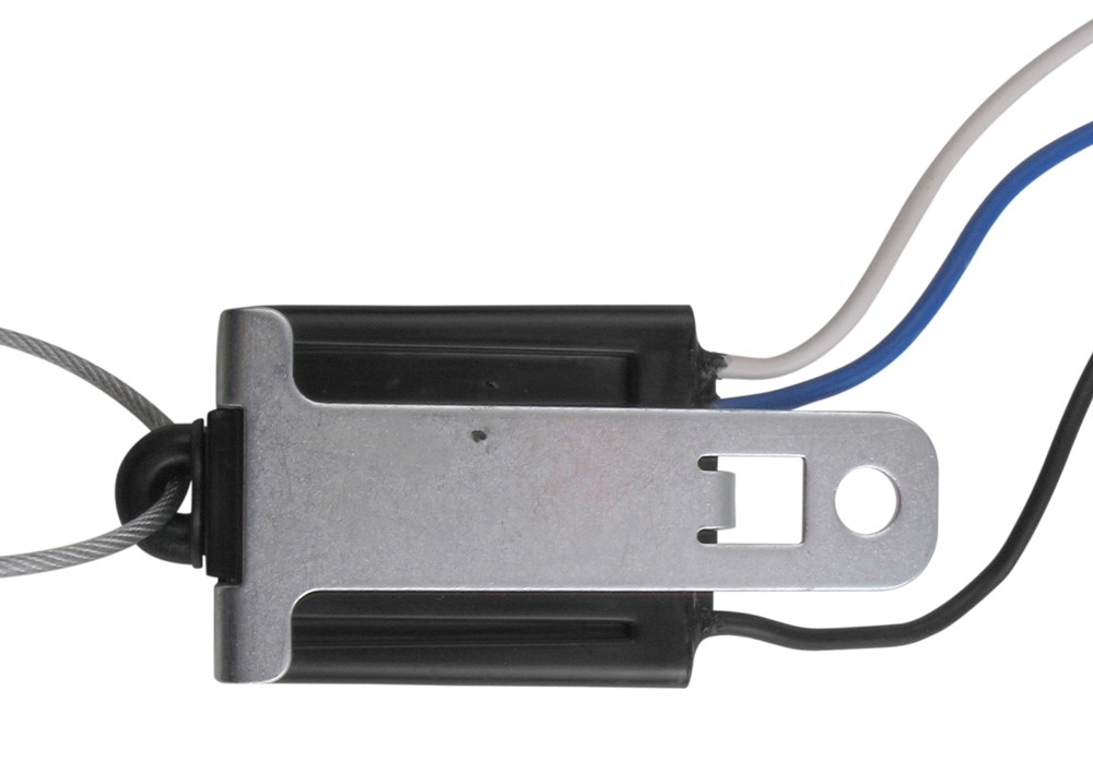
The engager breakaway system wiring diagram. Trailer Breakaway Battery Wiring Diagram - Folks understand that trailer is a vehicle comprised of quite complicated mechanics. This vehicle is designed not just to travel one location to another but also to take heavy loads. This report will be discussing trailer breakaway battery wiring diagram.What are the benefits of knowing such understanding? trailer breakaway switch wiring diagram. The Engager Break-Away System is designed to bring trailers safely to a stop wire coming from the trailer side connector A - see … Desember 28, 2021 Edit. Gerwyn Images Price. Gerwyn Price. › hopkins trailer brake wiring diagram ... Trailer Break-Away Kits. Protect your trailer investment with The Engager™ trailer break-away kit. Each kit has built in features that ensure that you have the safest towing experience possible. ***LEGALLY REQUIRED IN MOST STATES AND PROVINCES***. This Engager model is a front mount unit with tester. Carlisle Braking Systems does not recommend using this product on Disc Brakes. "There is a possibility of the brakes not releasing completely, resulting in damage to the brake system." Replacement Break-Away Pin and Cable Available, Part No. 20051
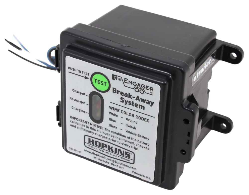
SEE WIRING DIAGRAMS ON REVERSE SIDE ... The Engager™ Break-Away System is designed to bring trailers safely to a stop by activating electric brakes, ... The Engager™ Break-Away System is designed to bring trailers safely to a stop by activating Follow “Wiring Installation”. WIRING DIAGRAM ON BACK. WIRING INSTRUCTIONS: 1. Splice one blue wire of the Break-Away Switch to the electric brake wire coming from the trailer side connector (A - see diagram on . I have all of the wires hooked up except the black wire on the switch. connect to the blue wire from the break away box, as shown in the provided diagram. Hopkins Engager Push-To-Test ... 7-Pin Connector. This 3 Wire Trailer Breakaway Switch Wiring Diagram model is much more acceptable for sophisticated trailers and RVs. It can transfer electricity better compared to the connector is suggested for higher-level electric in the vehicle. Here is the diagram for 7-pin connector. White Pin for the ground. Jul 12, 2018 · Tow Ready Trailer Break Away Kit Installation - Video Replacement Battery for Hopkins Engager Trailer Break Away System. The Engager™ Break-Away System is designed to bring trailers safely to a stop wire coming from the trailer side connector (A - see diagram on next page). Test your Break-Away Kit before each outing as described in Step 5 of the wiring . How to Wire Break Away Switch on Hopkins Engager Break Away System.
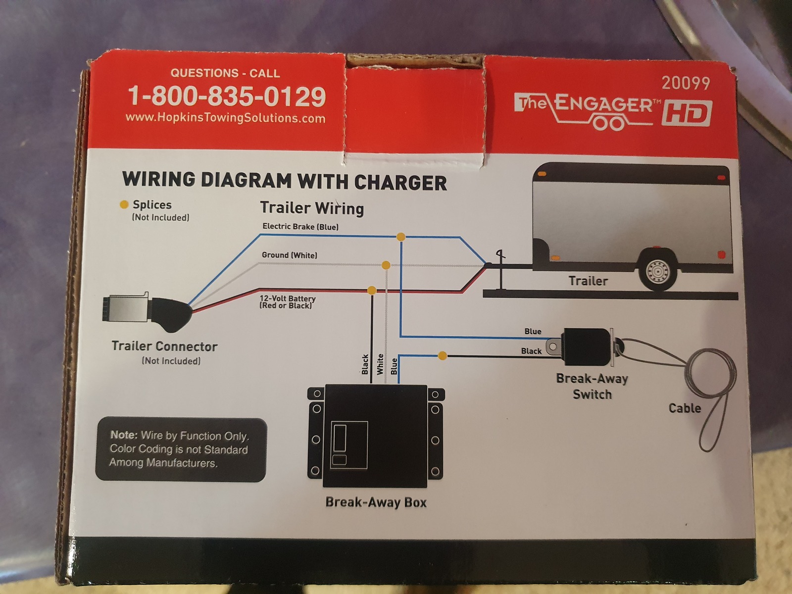
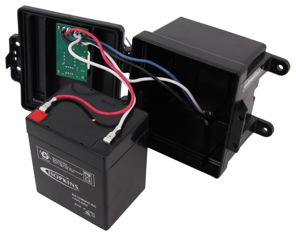
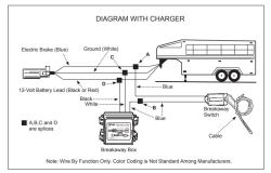
Break-Away System for Single and Tandem Trailers ... BAIO-250 Break-Away Kit, Engager, 5 A/H Battery, Charger, Switch, LED Test Lights, Top Open BAI 0-150 ... BA01-020 Battery, 12V, 5 A/H Sealed, Rechargeable BA02-020 SEE WIRING DIAGRAMS ON PAGE 2 . DIAGRAM WITH CHARGER DIAGRAMA CON EL CARGADOR DIAGRAMME AVEC CHARGEUR Blue / Azul / Bleu The Engager Breakaway System Wiring Diagram. The black wire on the Engager breakaway system 20099 will be connected to a 12v auxiliary power wire coming off of the trailer connector. Wiring Directions for Hopkins Engager Push-to-Test Trailer Breakaway Kit. Review of Hopkins The Engager HD Break-Away System. I was a disappointed with this product for a few reasons. The case is not sealed against water ingress and the electronics is a simple diode charger with battery charge state monitor. In addition the electronics has no protection whatsoever. Sr3b261fu Wiring Diagram- wiring diagram is a simplified welcome pictorial representation of an electrical circuit.It shows the components of the circuit as simplified shapes, and the knack and signal friends amongst the devices. A wiring diagram usually gives guidance roughly the relative approach and bargain of devices and terminals on the devices, to put up to in building or servicing the ...
Wiring Diagram Gallery: Wiring Diagram For Trailer ...
The engager break away system is designed to bring trailers safely to a stop by activating electric brakes should a trailer be disconnected while drivingthis type of safety system is required in most states on trailers rated over 3000 lb. Check your brakeaway system periodically to insure that wiring and connections are secure.

36 2 Wire Breakaway Switch Wiring Diagram - Wiring Diagram ...
The black wire on the Engager breakaway system # 20099 will be connected to a 12v auxiliary power wire coming off of the trailer connector. This wire is typically the number 4 black terminal in the 7-way connector, but you will need to test to determine if your plug is wired this way, as the auxiliary function can also be located on the center pin.

Hopkins Trailer Brake Control Wiring Diagram - Wiring Schema
Aug 12, 2016 — Wiring Diagram for Trailer Breakaway Kit On this page (typically below the product links) there is a helpful link section that will have the ...1 answer · Top answer: I have attached the installation instructions for the Hopkins Engager Trailer BreakAway Kit, part # 20099. This kit includes a charger and an LED tester ...

Hopkin Trailer Wiring Diagram - Wiring Diagram
The black wire from the break away switch will connect to the blue wire from the break away box, as shown in the provided diagram. By 'brake wires' I'm assuming you're speaking of the wires connected to the brake magnets on your brake assemblies. One wire exiting the brake magnet could connect to the brake output circuit, usually a blue wire ...
53 Redline Brake Controller Wiring Diagram - Wiring ...
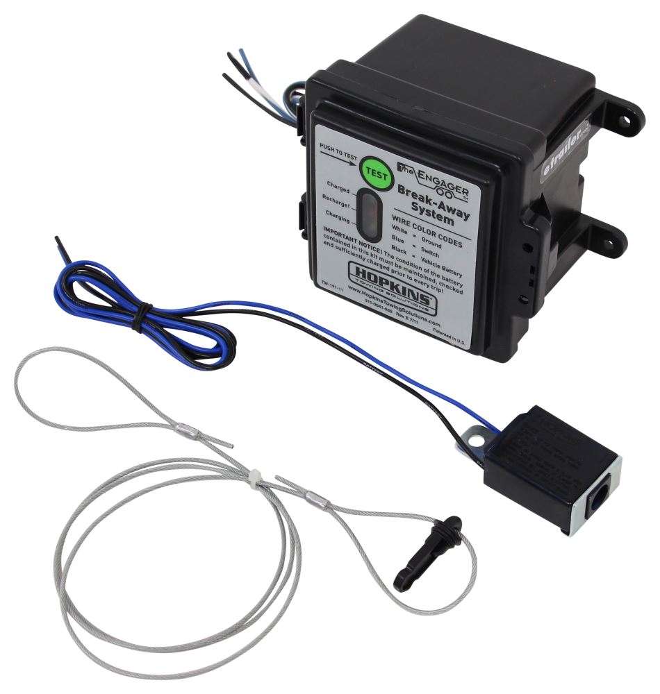
1. Splice one blue wire of the Break-Away Switch to the electric brake wire coming from the trailer side connector (A - see diagram on next page). 2. Connect other blue wire of Break-Away Switch to the blue wire (labeled “Brake”) from the Break-Away box (B). (Note: Blue wires are interchangeable on the Break-Away Switch.) 3.

Hopkins Towing Solutions Engager Breakaway Kit with LED ...
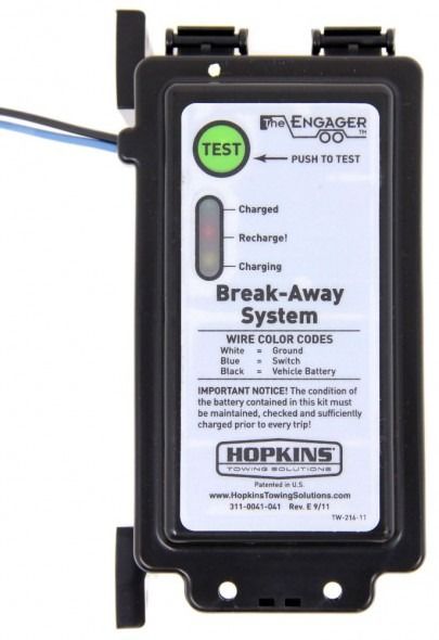
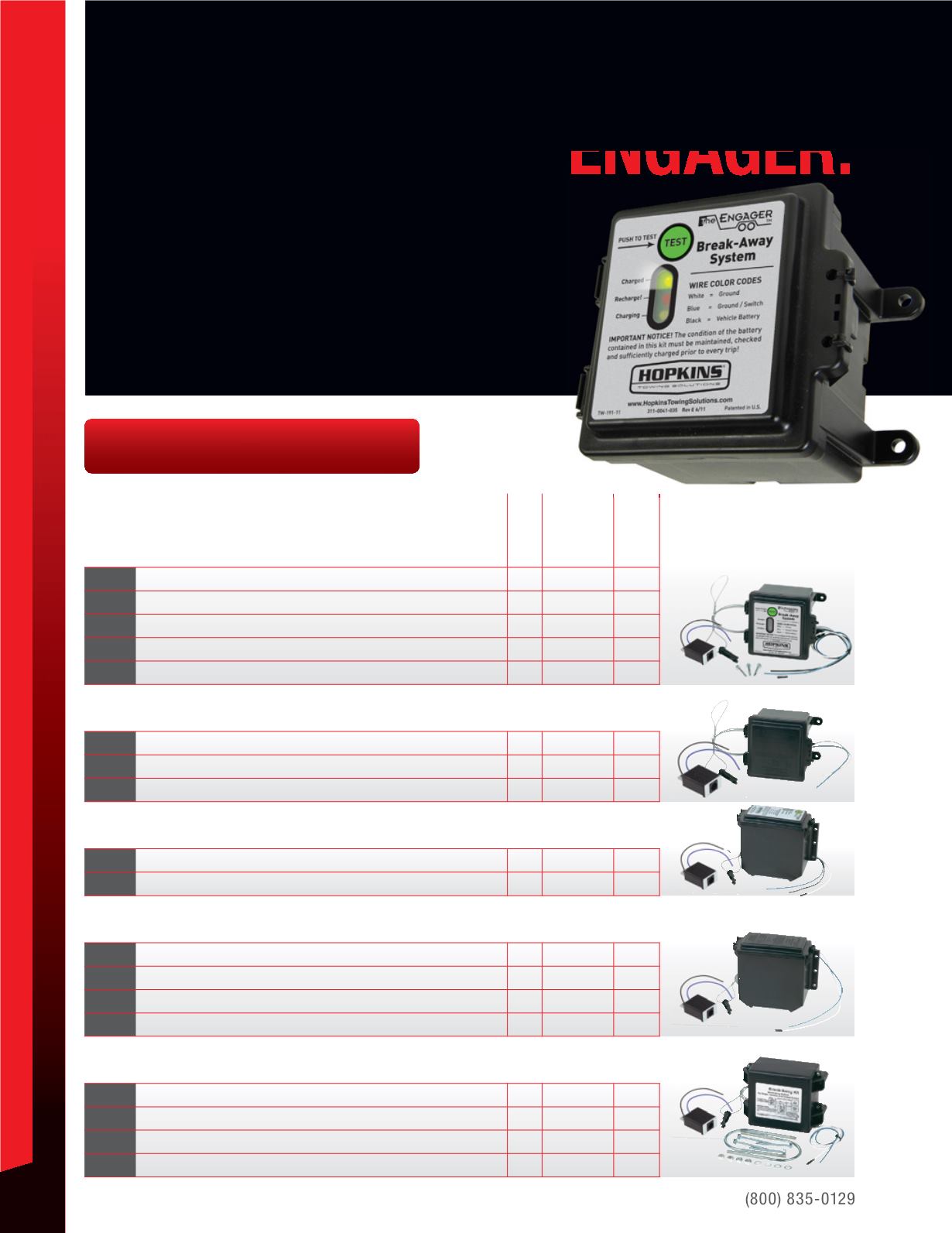
The Engager trailer breakaway system changes the way consumers protect their trailer investment, providing: Built in battery meter and charger with LED test lights. LEDs indicate: fully charged, re-charge or charging. Suits 1 o 2 braked axles.
Hopkins Engager Wiring Diagram
The Engager Break-Away System is designed to bring trailers safely to a stop wire coming from the trailer side connector A - see diagram. 1-4 Wire the first 4 pins White Brown Yellow Green just like the 4-pin connector above. These updates provide information on how to safely operate and maintain your Carry-On Trailer.
Hopkins Agility Brake Controller Wiring Diagram For 2007 ...
You Save $23.39! The Engager Breakaway System features a clamshell-style battery box with built-in battery meter to verify battery charge. For use on 1 or 2 axle trailers. Includes side-mount battery box, 5-amp battery, charger, breakaway switch with 7" leads and hardware. Breakaway kit exceeds D.O.T. regulation 393.43 (d)
37 Hopkins Breakaway Switch Wiring Diagram - Wiring ...
Hopkins 20099 Engager LED Test Break Away System with Battery Meter . JJThe Engager Break-Away System is designed to bring trailers safely to a stop by activating electric brakes, should a trailer be disconnected while driving. This type of safety system is required in most states on trailers rated over 3,000 Lb. GVW.
![[DIAGRAM] The Engager Hopkins Wiring Diagram FULL Version ...](https://images.etrailer.com/static/images/pics/r/i/rid448164_r1_800.jpg)
[DIAGRAM] The Engager Hopkins Wiring Diagram FULL Version ...
Hopkins 20099 Engager LED Test Break Away System with Battery Meter. JJThe Engager Break-Away System is designed to bring trailers safely to a stop by activating electric brakes, should a trailer be disconnected while driving. This type of safety system is required in most states on trailers rated over 3,000 Lb. GVW.

While I was away on a weeks holiday to Portugal, I decided to take a chance on seeing where the Milky Way and the Moon would be showing in relation to my location. To my surprise, the Moon was always below the horizon when the Milky Way was up. This was my first proper time photographing the Milky Way and I was seriously lucky to have really good conditions to capture it in. Would make a good phone background :)
May 11, 2019 · The Engager Breakaway System Wiring Diagram www.pinterest.com. Seven Pin Trailer Connector Wiring. 220v 30a Receptacle. Changing Dryer Cord 3 To 4. Single Pole Switch And Grounding Receptacle Wiring. Maytag Dryer Plug Adapter. Electrical Plug Diagram. Hvac Trailer Setup. 2004 Durango Wiring Diagram.

Compare Hopkins Engager vs Tekonsha Push-To-Test ...
The Engager™ Break-Away System is designed to bring trailers safely to a stop by activating electric brakes, should a trailer be disconnected while driving. This type of safety system ... WIRING DIAGRAM ON BACK CABLE INSTALLATION FIG 1 FIG 2 FIG 3 CABLE CABLE CABLE BREAK-AWAY SWITCH BREAK-AWAY SWITCH BREAK-AWAY SWITCH BUMPER CLEVIS SAFETY ...

Breakaway Trailer Brake Wiring Diagram Brilliant The ...
Break-Away Box: SEE WIRING DIAGRAMS ON REVERSE SIDE ... Screws 20400, 20401 (3 with 20099, 4 with 20400) The Engager™ Break-Away System is designed to bring trailers safely to a stop by activating electric brakes, should a trailer be disconnected while driving. This type of safety system is required in most states on trailers rated over ...

3 Wire Trailer Breakaway Switch Wiring Diagram | Trailer ...
Jan 12, 2018 · Follow "Wiring Instructions". WIRING INSTRUCTIONS: BREAK-AWAY SWITCH FIG. 2 BREAK-AWAY SWITCH SAFETY CHAIN POCKET BUMPER CLEVIS FIG.I CABLE PIN BREAK-AWAY SWITCH FIG. 3 CABLE INSTALLATION 1. Splice one blue wire of the Break-Away Switch to the electric brake wire coming from the trailer side connector (A - see diagram on next page). 2. The Engager is designed to activate the trailer brakes in the event the trailer is separated from the towing vehicle. Trailer break-away kits are legally ...
Hopkins Engager Push-To-Test Trailer Breakaway Kit w ...
Jun 20, 2019 · The Engager Breakaway System Wiring Diagram – wiring diagram is a simplified customary pictorial representation of an electrical circuit. It shows the components of the circuit as simplified shapes, and the talent and signal friends amid the devices.
Hopkins Engager Push-To-Test Trailer Breakaway Kit w ...

Trailer Brake Battery, Wiring Diagram Simple The Engager ...
Compare Hopkins Engager vs Tekonsha Push-To-Test ...

Installation Instructions For Hopkins Engager Trailer ...

Trailer Wiring Diagram 7 Way With Breakaway | Trailer ...

Hopkins Towing® 20419 - Engager™ FT Breakaway System
Compare Cargo Towing Solutions vs Hopkins Engager ...

Hopkin Trailer Wiring Diagram - Wiring Diagram
Can I Use Curt Replacement Breakaway Switch With TAP ...

Hopkins Engager Wiring Diagram

Mars planet, beach lounger
The Engager Breakaway System Wiring Diagram

CaravansPlus | Hopkins The Engager Break-Away System

27 Trailer Breakaway Switch Wiring Diagram - Wiring ...
The Engager Breakaway System Wiring Diagram

I love ceramic table ware (check out that squeezer!) so i combined these elements to give that organic breakfast feel.

The Engager Breakaway System Wiring Diagram

18 New Esco Breakaway Switch Wiring Diagram
Hopkins Engager Push-To-Test Trailer Breakaway Kit w ...
Hopkins Engager Wiring Diagram
46 Hopkins Trailer Breakaway Wiring Diagram - Wiring ...

7, Trailer Wiring Diagram With Brake, Breakaway Creative ...

File Php Id 7084 For Break Away Systems Wiring Diagram ...

Tekonsha Breakaway Trailer Wiring Diagram - Complete ...

10 Cleaver Trailer Brake Wiring Diagram With Battery ...

Compare Hopkins Engager vs Tekonsha Push-To-Test ...
The Engager Breakaway System Wiring Diagram

11 Creative Hopkins Trailer Breakaway Wiring Diagram ...
Comments
Post a Comment