43 battery disconnect switch wiring diagram
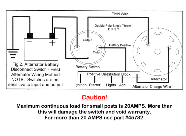
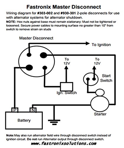
Oct 1, 2019 — 1) Get a switch · 2) Get a hunk of copper wire with lugs on it · 3) Pull the wires off the negative side of the battery. · 4) Hook them to one side ... Kill Switch. They have 4 post kill switches, rather than the common 2 post. You will have the heavy posts for the positive break from the battery to all other systems in you car. But, you will also have smaller post for a positive break to the alternator field wire that will pass through the switch to the plus side of the battery through the 2 ...
Pyrotech Kill Switch 2 Dead Alternators Page 1 Lemons Tech The 24 Hours Of Forums. Should the kill switch be hooked up 4430 master battery cut off instructions easy diy disconnect install wiring stangnet disconnects 101 ce auto diagram exciter harness kit circuit without ecu car installing a for longacre 4 terminal 2 dead alternators boat vehicles switches te with efi nhra remote batter china ...

Battery disconnect switch wiring diagram
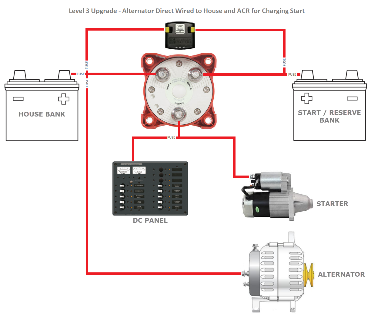
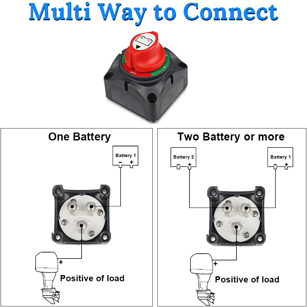
RV Make: itasca, RV Model: sunstar 26P, RV Year: 2012, Brand: Intellitec Battery disconnect. June 14th, 2017 . Wiring diagram for interfacing Intellitec latching solenoid battery disconnect system w/ 8-prong Winnebago momentary dual pole-dual throw switch … have solenoid wire details, searching for switch input/output diagram. Reply WIRING. 1. Disconnect the positive and negative battery terminal. Make sure the switch in the off position. 2. Connect a battery cable from the starter or starter solenoid to one of the 1/2" switch terminals. The battery cable should be a minimum of 2-gauge wire. 3. Connect a jumper wire from the alternator output terminal to one of the 3/16 ... Battery Disconnect Switch Wiring Diagram This battery disconnect is intended to disable the vehicle with an alternator in the event of an emergency. The following diagram is intended for reference only. Due to the many deferent applications and variations of components, it is the responsibility of the installer to verify correct connections.
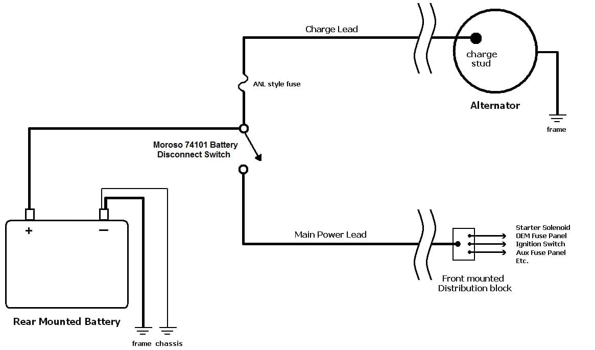
Battery disconnect switch wiring diagram. This battery disconnect is intended to disable the vehicle with an alternator in the event of an emergency. The following diagram.1 page Battery Disconnect Switch Wiring Diagram. May 15, 2020 · Wiring Diagram. by Anna R. Higginbotham. battery disconnect switch wiring diagram - You will want a comprehensive, skilled, and easy to know Wiring Diagram. With this kind of an illustrative manual, you will have the ability to troubleshoot, stop, and total your assignments easily. Redsnk95. Power wire from the battery through the battery cutoff switch to the power distribution box. Reused the stock power wire from the distribution box to the starter. Unhook the stock alternator wiring and ran a 6 gauge wire from the alternator to the battery cutoff switch. Works just fine and the car shuts off when you hit the switch. The 4430 switch has a third set of contacts (labeled "Z"), which interrupts the ignition circuit when the switch is turned off. Wiring the 4430 Kill Switch. Turn the car off and disconnect the negative battery cable. Cut the positive battery cable near where the switch will be located. Install 3/8" ring terminals on each cut end.
HOW TO WIRE A BATTERY DISCONNECT SWITCH | DOITYOURSELF.COM · Disconnect the Negative Terminal. Using a wrench, remove the connection on the negative terminal of ... WIRING . 1. Disconnect the positive and negative battery terminals. 2. Once the switch has been mounted, attach the positive battery cable to the most convenient . 3/8" lug. Note the location of the lug as either the "A" or "B" side. 3. Then connect the alternator output to other lug (A or B) on the same side of the switch. This Installing a battery disconnect switch in a car can save lives if used in the proper situation. These switches are wired to a car's battery and can be used to instantly cut the power to an engine in an emergency situation. So, not surprisingly, these switches are most often used in race cars where the odds of the driver being in a catastrophic crash are much greater than that of most drivers. Battery Disconnect Switch Wiring Diagram - 4 post battery disconnect switch wiring diagram, battery cut off switch wiring diagram, battery disconnect switch wiring diagram, Every electrical arrangement is made up of various unique pieces. Each part ought to be set and linked to other parts in specific manner. If not, the structure will not work as it ought to be.
Apr 24, 2019 — Usually, I see battery disconnect switches wired in on the positive side of the battery. Here is a simple wiring diagram I found on Google.Battery disconnect switch install - Jayco RV Owners ForumFeb 18, 2021Battery Disconnect Wired Wrong from Factory? - Jayco ...Jul 28, 2018Battery disconnect switch doesn't disconnect anything - Jayco ...Dec 5, 2017Wiring Layout-Battery Disconnect - Jayco RV Owners ForumAug 23, 2017More results from www.jaycoowners.com Marine Battery Disconnect Switch Wiring Diagram from www.boatdesign.net. Print the electrical wiring diagram off plus use highlighters to trace the signal. When you make use of your finger or the actual circuit with your eyes, it may be easy to mistrace the circuit. A single trick that I actually use is to print the same wiring plan off twice. Wiring diagram supplied in the kit shows how everything should be connected. The kit places a disconnect solenoid in the hot lead from the battery to the starter with a switch to activate/deactivate the solenoid. A mounting plate for the solenoid was designed and cut out of aluminum plate. Then punched and drilled for the mounting hardware. Disconnect Switch Wiring Diagram. Disconnect Switch Wiring Diagram - wiring diagram is a simplified customary pictorial representation of an electrical circuit. It shows the components of the circuit as simplified shapes, and the talent and signal contacts in the company of the devices. A wiring diagram usually gives guidance not quite the ...
Intellitec Battery Disconnect Relay Wiring Diagram | Free ...
Rv Battery Disconnect Switch Wiring Diagram Gallery. rv battery disconnect switch wiring diagram - What's Wiring Diagram? A wiring diagram is a kind of schematic which utilizes abstract photographic icons to show all the affiliations of components in a system. Electrical wiring layouts are made up of 2 things: signs that stand for the components in the…

Windows in clouds, clouds in windows - instagram.com/pwellgraf
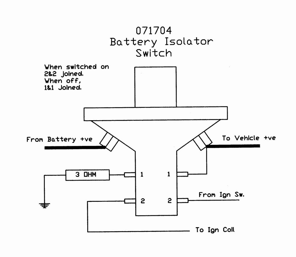
Battery Disconnect Switch WIRING DIAGRAM 3/8" Terminal FORD GM FIELD WIRE FORD ONE WIRE GM Terminal #1 STARTER BATTERY DISCONNECT 3/8" Terminal 10/32" Studs This battery disconnect is intended to disable the vehicle with an alternator in the event of an emergency. The following diagram is intended for reference only.

Battery Disconnect Switch Wiring Diagram | Fuse Box And ...
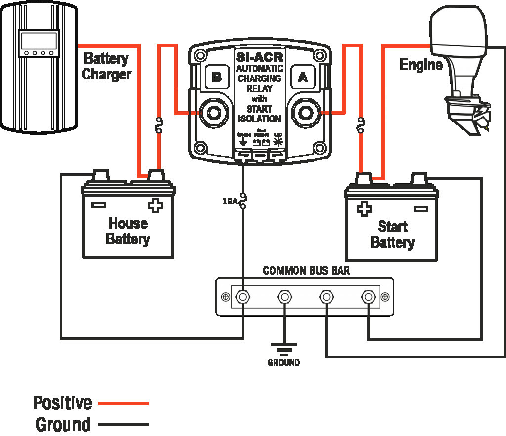
The Battery Disconnect Relay is a mechanically latching switch that operates by the momentary application of battery voltage to the coil terminals in one direction for latching (closed) or the other direction for unlatching (open). To close the relay, +12 volts is applied to the "I" terminal and ground to the "S" terminal of the relay. When

RV.Net Open Roads Forum: Tech Issues: Catastrophe fuse ...
Thank you. In your newsletter #20 you talked about disconnect switches and said you would do an extended article on the subject in a few weeks. Not sure if you have or I missed a newsletter, but I'm interested in a wiring diagram of two 6-volt batteries in series and connecting a disconnect switch. I have a 2-post on-off switch.

How To Wire A Disconnect Switch Brilliant ... Disconnect ...
12v Battery Disconnect Switch Wiring Diagram By Unknown December 19, 2020 Post a Comment Pin On Electrical . 3 Way Switch Wiring Diagram Home Electrical Wiring Diy Electrical 3 Way Switch Wiring . Universal Ignition Switch Wiring Diagram Boat Wiring Trailer Wiring Diagram Kill Switch .
Marine Battery Disconnect Switch Wiring Diagram Database
Using supplied template drill holes and install switch 3. Follow the wiring diagram for proper hookup NOTE: In order for vehicles with alternators to meet NHRA regulations, the alternator output wire must be wired to the battery side of the disconnect switch. On racecars and streetcars with modified wiring harness, we recommend the use of a ...

35 Cole Hersee Solenoid Wiring Diagram - Wiring Diagram List
battery disconnect switch wiring diagram - thanks for visiting my internet site, this article will certainly go over concerning battery disconnect switch wiring diagram. We have actually gathered several pictures, with any luck this picture serves for you, as well as assist you in finding the answer you are searching for.

33 Battery Disconnect Switch Wiring Diagram - Wiring ...
Installing a battery disconnect switch to kill the car's power is an easy solution to the battery draining while the ignition is off.Mar 5, 2021

Ignition Cylinder Problems?
It is very simple, run the big power wire from the back of the alternator to the same side of the switch that you hook the positive battery cable to. This will disconnect the alternator when you shut the switch off. Eric Millard. bigblok86gt@yahoo.com. 528ci of N/A power. Circle R Racing Engines.

21 Beautiful Race Car Kill Switch Wiring
Camper Battery Wiring Diagram Rv Disconnect Of Switch Like Diag - Rv Battery Disconnect Switch Wiring Diagram. Wiring Diagram consists of several in depth illustrations that show the connection of varied products. It includes guidelines and diagrams for different kinds of wiring techniques and other products like lights, windows, etc.

BOBCAT SKID STEER BATTERY TRAY REPLACEMENT - YouTube
Name: intellitec battery disconnect relay wiring diagram - rv battery disconnect switch wiring diagram Search and free form templates and tested template designs Download for free for mercial or non; File Type: JPG; Source: canhodatgiaresidence.org; Size: 228.01 KB; Dimension: 1024 x 600
Battery Disconnect Switch? - TinBoats.net
The battery is already relocated switch mounted on back of car. it runs as is. my question is for the alternator wiring. it has to be wired through the disconnect switch to it will turn the car off from the switch. my question is how do i wire the alternator to the switch. wouldnt running the wire from the alternator to the switch directly affect the wiring to the regulator?

Rv Battery Disconnect Switch Wiring Diagram - Wiring Diagram
Wiring a Perko Battery Switch. There are many ways to use a Perko Battery On-Off Switch. The most obvious (and most common) is simply to use it to turn off your battery when in storage so that your battery does not drain as quickly and is ready to go when you are. Like all Perko products, these time-proven switches are made in the USA.
Marine Battery Disconnect Switch Wiring - Rv Battery ...
I've searched, found some interesting topics. Found the wiring diagram from the Renault guy. But, can't find a single wiring diagram/picture/FAQ for hondas ...

Battery Disconnect Switch Wiring Diagram | Fuse Box And ...
May 15, 2020 · Wiring Diagram. by Anna R. Higginbotham. battery disconnect switch wiring diagram - You will want a comprehensive, skilled, and easy to know Wiring Diagram. With this kind of an illustrative manual, you will have the ability to troubleshoot, stop, and total your assignments easily.

Battery Master Disconnect Switch Wiring Diagram ...
We have analyzed thousands of reviews in order to decide on what the best Boat Battery Switch Wiring Diagrams of the year are. The Best Boat Battery Switch Wiring Diagrams of 2022 GOGONFLY Battery Switch 12-48V Battery Power Cut Master Switch Disconnect Isolator Cut Off Switch for Marine Boat Car Truck Camper RV Trailer Vehicles (On/Off)

Used batteries ready for recycling
Battery Disconnect Switch Wiring Diagram This battery disconnect is intended to disable the vehicle with an alternator in the event of an emergency. The following diagram is intended for reference only. Due to the many deferent applications and variations of components, it is the responsibility of the installer to verify correct connections.
Unplugged black cord
WIRING. 1. Disconnect the positive and negative battery terminal. Make sure the switch in the off position. 2. Connect a battery cable from the starter or starter solenoid to one of the 1/2" switch terminals. The battery cable should be a minimum of 2-gauge wire. 3. Connect a jumper wire from the alternator output terminal to one of the 3/16 ...
B+ Battery Cable From Alternator To Battery Wiring Diagram
RV Make: itasca, RV Model: sunstar 26P, RV Year: 2012, Brand: Intellitec Battery disconnect. June 14th, 2017 . Wiring diagram for interfacing Intellitec latching solenoid battery disconnect system w/ 8-prong Winnebago momentary dual pole-dual throw switch … have solenoid wire details, searching for switch input/output diagram. Reply
Battery Disconnects 101 - CE Auto Electric Supply

http://www.truckt.com Heavy Duty Truck Starters Explained

Can I use a 4 pole kill switch without killing my ...

Perko Dual Battery Wiring Diagram - Wiring Diagram

How To Wire A Disconnect Switch Most 3 Phase Disconnect ...
Trunk Mounted Battery Disconnect Switch? - NJFBOA - Home ...

16 New Disconnect Switch Wiring Diagram
Battery disconnect switch circuit? - Ford Truck ...

2, Battery Switch Wiring Most Luxury Rv Battery Disconnect ...

Battery Disconnect Switch Wiring Diagram - antoneanews
Battery cables and disconnect wiring? - LS1TECH - Camaro ...
29 Rv Battery Disconnect Switch Wiring Diagram - Wire ...
Rv Battery Disconnect Switch Wiring Diagram - Wiring Diagram
Battery Disconnect Switch Wiring Diagram - Hanenhuusholli
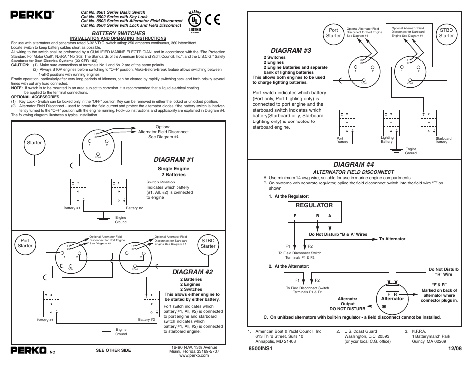
PERKO 8502 User Manual | 1 page | Also for: 8503, 8504, 8501

Rv Battery Disconnect Switch Wiring Diagram | Free Wiring ...

Flaming River Wiring Diagram - Wiring Diagram & Schemas
MARINE DUAL BATTERY DISCONNECT SWITCH AUTO BOAT 1-2-BOTH ...

Battery Disconnect Switch Symbol Schematic | Wiring ...

Wiring A Battery Disconnect Switch | schematic and wiring ...
Battery Disconnect Switch Wiring Diagram | Cadician's Blog
Solve the battery disconnect switch wiring dilema once and ...

Battery sharing is growing steadily and fast. No time to charge your Battery? Shove it into the Swobbee charger and exchange your Kumpan Electric battery for a full one. As simple as that.💚

Battery Selector Switch Wiring Diagram Collection
Comments
Post a Comment