42 pressure enthalpy diagram refrigeration cycle
Refrigeration process pressure-enthalpy diagram. The condensed refrigerant in the condenser in a state that lies on the line for the boiling point of the liquid. Liquid, thus, the temperature tc, pressure pc also called saturated temperature and pressure. The condensed liquid in the condenser is cooled additionally in the refrigerator up to a temperature of A1 and now has a temperature tl and enthalpy of h0. Let's look at what happens in a simple refrigeration cycle, and to the major components involved. Two different pressures exist in the cycle - the evaporating or low pressure in the "low side," and the condensing, or high pressure, in the "high side." These pressure areas are separated by two dividing points: one is the...
Mollier charts are used in designing and analyzing performance of vapour compression refrigeration systems. Each refrigerant has it's own chart which is a graph of the Enthalpy of a refrigerant during various pressures and physical states. Mollier charts are also called Pressure-Enthalpy diagrams.

Pressure enthalpy diagram refrigeration cycle
Pressure enthalpy diagram of a propane refrigeration cycle. This paper has applied thermodynamics principles to evaluate the reliability of 390m3/hr natural gas processing plant. The ... pressure - enthalpy diagram (p - h) and professional charts are available but not used in the Engineering Council exams. Figure 3 shows the basic cycle. ... There are two coefficients of performance for such a cycle, one for the refrigeration effect and one for the heat pump effect. Mollier Diagram of Pressure & Enthalpy of GAS
Pressure enthalpy diagram refrigeration cycle. M. Bahrami ENSC 461 (S 11) Refrigeration Cycle 3 Fig. 5-3: T-s and P-h diagrams for an ideal vapor-compression refrigeration cycle. 1-2: A reversible, adiabatic (isentropic) compression of the refrigerant. This case is to review the practical use of the Pressure-Enthalpy (P-H) diagram and the thermodynamic analysis of the refrigeration cycle using the P-H diagram; the Refrigerant Flow Diagram corresponding to the P-H Diagram. This case is also to evaluate various cycles such as with penalties, economizing for a same pressure is about 35 F that’s what makes it excellent for freezers. And so on. Well that was a very heavy topic aren’t you glad we got it over with? So let’s move forward to the refrigeration cycle so we can see how it’s all come together. But before we go there, here is some Real diagram for Please email your... The purpose of the compressor in the refrigeration cycle is to accept the low-pressure dry gas from the evaporator and raise its pressure to that of the condenser. The rate of heat absorption by the evaporator differs from different cargoes carried and the outside air temperature. Sometimes cargo/stores are freshly located in a...
enthalpy (kJ/kg) q specific refrigeration effect (kJ/kg) s specific entropy (kJ/kg K) t temperature (8C) w actual specific work (kJ/kg) COP coefficient of performance I specific irreversibility (kJ/kg) P pressure (bar)... In the T–s diagram, the line 1–2 s –3–4 s –1 shows the ideal refrigeration cycle with an expander... Larger is the irreversibility in a refrigeration cycle operating with a given refrigeration load between two fixed temperature levels, larger is the amount of work required to operate the cycle. Irreversibility includes pressure drops in lines and heat exchangers, heat transfer between fluids of different temperatures, and ... Enthalpy is the ... Figure 6- Pressure-enthalpy diagram of an ideal refrigeration cycle. Figure 7- L F D diagram of a real refrigeration cycle. To calculate the refrigerating capacity, i.e., heat transfer from low temperature source, 3 6 Å, the refrigerant mass flow rate I 6 should be known beforehand. The specific volume å for the refrigerant is read from the L Refrigerant flows through the compressor, which raises the pressure of the refrigerant. Next the refrigerant... In dealing with one specific refrigerant, the enthalpy values depend on the temperatures in the warm and cold regions. The surrounding temperature affects how well the refrigeration system is able to cool the enclosed...
The basic refrigeration cycle for beginners If we are interested in learning how a refrigeration system works, it is helpful to understand from the Ph (Pressure Enthalpy) chart perspective. It makes our life easier. This is how the refrigeration cycle diagram looks: Yeah, it seems complicated at first, but it will be easier to... If you are interested in learning how a refrigeration system works, it is helpful to understand from the Ph (Pressure Enthalpy) chart perspective. It makes our life much easier. This is how the refrigeration cycle diagram looks: Yeah, it seems complicated at first, but it will be easier to understand once I have explained the refrigeration ... Pengecekan Kebocoran Sistem Refrigerasi (Leaks Testing) Basic Refrigeration Cycle Refrigeration Component and Its functionRefrigerant Pressure Gauges COP... Compressor Pressure-Enthalpy Diagram Domestic Refrigerator/Freezer System Refrigerator Starting Relay Incorrect Defrost Thermo Placement Domestic Refrigerator Parts... Hot Gas Bypass (HGBP) and the Pressure Enthalpy Diagram. Hot gas bypass (also called discharge bypass) is a feature in a refrigeration system uses to satisfy the mechanical needs of the system during low load conditions. Low load conditions can lead to frosting or freezing the evaporator, refrigerant flood back to the compressor, system ...
P-h diagram of the vapour-compression refrigeration cycle ...
q H = h 2 − h 3 3-4: An irreversible throttling process in which the temperature and pressure decrease at constant enthalpy. The refrigerant enters the... Actual Vapor‐Compression Refrigeration Cycle Fig. 5-4: T-s diagram for actual vapor-compression cycle. Most of the differences between the ideal and the actual cycles are...

The Refrigeration Cycle - In easy to understand ...
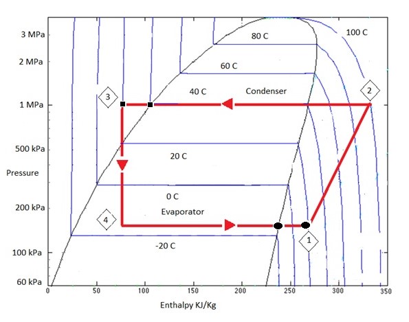
04/33 Ideal refrigeration Cycle Process Flow Diagram Pressure Enthalpy Diagram Compressor Condenser Expansion Valve Evaporator D AB C A B C D △Hevap T B =T C T A T D P A , P D P B , P C P H By utilizing the Pressure-Enthalpy (P-H) diagram, the refrigeration cycle can be broken down into four distinct steps : Expansion...

Visited edinburgh in Scotland over the christmas period. sadly didnt get out much to take pictures. However, here’s a quick grab shot of a cyclist. Not one of my finest works, but I just love the way the sun lights the scene and the dudes hair.
used refrigeration cycle is the vapor-compression refrigeration cycle. In an ideal vapor-compression refrigeration cycle, the refrigerant enters the compressor as a saturated vapor and is cooled to the saturated liquid state in the condenser. It is then throttled to the evaporator pressure and vaporizes as it absorbs heat from the refrigerated ...

Pressure-enthalpy diagram of a refrigeration cycle with ...
Mar 12, 2018 ... Our unit is an air cooled 134a cycle with 10 degrees of superheat and 9 degrees of sub-cooling. The saturation temperature of the evaporator is ...
Pressure-enthalpy diagram of a refrigerant cycle in a heat ...
Learn refrigerant flow in a vapor compression system using a schematic of various components and a pressure enthalpy diagram.Please provide feedback on this ...
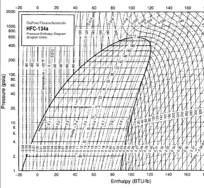
Pressure Enthalpy Diagram For Refrigerant 134a - Diagram Media
Joule-Thomson refrigeration cycle for 67 K with sub-atmospheric device Cryogenic Engineering Laboratory, Korea Advanced Institute... The temperature of 67 K is possible by lowering the pressure up to 24 kPa at the cold part. The optimized hydrocarbon mixed... The efficiency difference between the cold compressor system and the vacuum pump system is due to difference of enthalpy change at...

b: Pressure - enthalpy - diagram for the refrigeration ...
In this video we explain the importance of the P-H diagram and how useful this is for the refrigeration cycle. Gauge and absolute pressure is also explained ...

Pressure - enthalpy diagram for R744, R404A and R290 ...
Figure 4 is a pressure-enthalpy diagram of a typical refrigeration cycle in a system with one pound of HFC-134a. It uses (for this example) evaporating and condensing temperatures of 0°F and 120°F. Points on the diagram are labeled to correspond to locations of equipment in the system. Each step of the cycle can be approached separately.

Pressure - enthalpy diagram for the R744 two-stage ...
The Basic Refrigeration Cycle Mechanical refrigeration is accomplished by continuously circulating, evaporating, and condensing a fixed supply of refrigerant in a closed system. Evaporation occurs at a low temperature and low pressure while condensation occurs at a high temperature and high pressure.

Category: Using Pressure Enthalpy Diagrams - FUNDAMENTAL ...
refrigeration system should always be nearly filled with liquid refrigerant. Otherwise, its full potential as a heat transfer device will not be utilized. The pressure-enthalpy chart, as shown in Fig. 2, displays all the pertinent properties for a given refrigerant (in this example R22). The bubble to the left is the portion of the diagram where

The Refrigeration Cycle
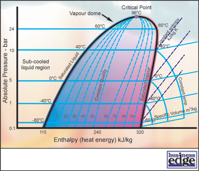
Understanding the P-H Diagram. On the P-H diagram, pressure is indicated on the y-axis and enthalpy is indicated on the x-axis. Typically enthalpy is in units of Btu/lb and pressure is in units of pounds per square inch (psi). The upside down U figure shown on the diagram designates the points at which the refrigerant changes phase.

Wiring Diagram: 29 Ph Diagram For Refrigeration Cycle
However, it is shown that the vortex tube may present a significant opportunity to improve the performance of refrigeration systems using the Joule-Thomson cycle and may allow efficient operation at lower pressure ratios, with smaller recuperative heat exchangers, and with less expensive working fluids than are currently used....
Heart in hand
It is used to predict the outcome of the various proces- ses that make up a refrigeration cycle. The first... are the heat and work crossing the control surface, m is mass, h is specific enthalpy, u is specific... Adequate pressure relief must be provided and the vent system must prevent atmosphefic gases from entering the cold...
What is meant by refrigeration effect? - Quora
As a result a pressure drop occurs. The process is irreversible. Applying SFEE: Therefore, h2 = h1 Pressure-enthalpy chart The ideal vapour compression cycle consists of two constant pressure process and one constant enthalpy process. So in preliminary cycle calculations pressure-enthalpy diagrams are particularly useful.

Vapor-Compression Refrigeration Cycle (Interactive ...
refrigeration cycle. International Journal of Refrigeration 28 (2005) 766–773 www.elsevier.com/locate/ijrefrig Nomenclature a area per unit total ejector flow rate COP coefficient of performance h specific enthalpy m mass flow rate P pressure Q heat capacity q specific heat capacity R relative performance s specific entropy t...

Pressure enthalpy diagram of a propane refrigeration cycle ...
• Pressure-enthalpy diagram for R -12 • Pressure-enthalpy table for R -12 • Vapor compression refrigeration system • P, T, H, and phase changes in a vapor compression refrigeration cycle 2 . Goals of Lab • To get acquainted with a vapor-compression refrigeration system • To be able to use pressure-enthalpy diagrams and

Refrigeration Cycle Pv Diagram — UNTPIKAPPS
vapor-compression refrigeration (VCR) cycle. The technique provides a simple and effective means of util... Thermodynamic cycle 1. Introduction In a companion to the present paper [1], a molecular dynamics technique was presented that e the direct simulation of isenthalpic pressure changes and isobaric enthalpy changes. The...

DBNSTJ : Development of High Performance Room Air ...
The pressure-enthalpy diagram is shown next. The enthalpy values are in while the pressure, which does not enter into the calculation, is presented on an arbitrary scale. The cold side of the cycle is shown in blue and the hot side in red. Note that certain allowable combinations of enthalpy values are not possible in actual refrigeration systems.

An image of a young person holding a ripe orange to show the similarity of the female genitalia.
We described the enthalpy content of the refrigerant under different state conditions (such as when it is a vapor or a liquid) on a Pressure-Enthalpy (PH) diagram. In the next video, we will draw a refrigeration cycle on a PH diagram. We will examine both the PH chart and the schematic diagram of the refrigeration components side-by-side.

A simplified ideal vapor compression refrigeration cycle ...
On the pressure-enthalpy diagram, sub-cooling occurs in the final stage of the condenser then continues, to a lesser extent, in the liquid line until it reaches the metering device. The diagram shows what 10 degrees of liquid sub-cooling looks like on a R-410a cooling cycle.

Pressure-enthalpy (a) and Temperature-entropy (b) diagram ...
refrigeration system should always be nearly filled with liquid refrigerant. Otherwise, its full potential as a heat transfer device will not be utilized. The pressure-enthalpy chart, as shown in Fig. 2, displays all the pertinent properties for a given refrigerant (in this example R22). The bubble to the left is the portion of the diagram where

Pressure/enthalpy chart of Rankine cycle with R134a for ...
The refrigeration cycle in the log p-h diagram The refrigeration cycle in the log p-h diagram The real refrigeration cycle consists of the following changes of state: 1 - 2 polytropic compression on the condensation pressure (for comparison 1 - 2' isentropic compression) 2 - 2'' isobaric cooling, deheating of the superheated steam
Solved: An Ideal R-134a Vapor Refrigeration Cycle Operates ...
Learn how to draw a cycle for ideal conditions on a PH chart.Please provide feedback on this module by selecting "Like" or "Dislike".

Pressure-Enthalpy (P-h) diagram of: (a) an ideal ...
(e) Constant pressure heat transfer would take place in the evaporator. All these ideal conditions can be shown by the following T-s diagram (Figure 5.3) Figure 5.3 T-S Diagram of Ideal Vapour Compression Refrigeration Cycle 5.6 PRESSURE ENTHALPY DIAGRAM The refrigeration industry did not always have the analysis tools that are available today.
Ph Diagram For Refrigeration Cycle - Drivenheisenberg
Law Calculations (using cycles) Making sense of temperature-entropy diagrams Pressure Enthalpy Chart \u0026 the Refrigeration Cycle Pressure - Enthalpy Diagram // Thermodynamics - Class 54 Refrigeration - Pressure Enthalpy Chart -refrigerant statesThe Basic Refrigeration Circuit, Pressure \u0026 Enthalpy w/ Carter Stanfield CTI Virtual Classroom -
Refrigeration: Enthalpy Change Refrigeration
1.1 The origins of refrigeration 6 1.2 The thermoelectric process 7 1.2.1 Temperature-enthalpy diagram 7 1.2.2 Heat flow 8 1.2.3 Melting process 9 1.2.4 Vaporization process 9 1.2.5 Superheating 10 1.2.6 Liquefaction process (condensation) 11 1.2.7 Pressure-enthalpy diagram 12 1.2.8 Refrigerants 12 1.2.9 Summary 13 2.1 Properties, history 15

Figure2.2: p-h diagram of simple refrigeration cycle ...
The refrigeration cycle is the main basic cycle for all air conditioning and refrigeration equipment. In this chapter, we will discuss, basics of a refrigeration cycle, mainly vapor compression cycle, main concept, parts, components, working principle along with a real example, etc.

Pressure-Enthalpy diagram for vapour compression cycle ...
pressure-enthalpy diagrams, can be developed for stable refrigerants.To develop these curves, it is nec-essary to vary the pressure and measure the amount 1 Refrigeration Service Engineers Society 1666 Rand Road Des Plaines, Illinois 60016 PLOTTING THE A/C CYCLE ON A PRESSURE-ENTHALPY (MOLLIER) DIAGRAM

Refrigeration Cycle: A Helpful Illustrated Guide ...
The pressure-enthalpy diagram (log P/h diagram) is a very useful tool for refrigerant technicians. First, an explanation of how the diagram is built up is given, and then its use is describ ed. Figure 2.1 shows the principle of a log P/h diagram, and indicates the refrigerant's various thermodynamic states. This diagram can be seen as a map of the refrigerant.

CHILLER CHOONG: The Basic Refrigeration Cycle
Mollier Diagram of Pressure & Enthalpy of GAS
Masterclass: Refrigeration Cycles - Part 3
pressure - enthalpy diagram (p - h) and professional charts are available but not used in the Engineering Council exams. Figure 3 shows the basic cycle. ... There are two coefficients of performance for such a cycle, one for the refrigeration effect and one for the heat pump effect.

P-h diagram of vapor compression refrigeration cycle ...
Pressure enthalpy diagram of a propane refrigeration cycle. This paper has applied thermodynamics principles to evaluate the reliability of 390m3/hr natural gas processing plant. The ...

12: The pressure enthalpy diagram of a refrigerant ...

CO2 as a Refrigerant — Introduction to Transcritical ...

Pressure–enthalpy diagram of thermodynamic cycle (R134A ...

Pressure enthalpy diagram of a propane refrigeration cycle ...

Category: Using Pressure Enthalpy Diagrams - FUNDAMENTAL ...

Pressure-enthalpy (a) and Temperature-entropy (b) diagram ...

LifeStyle, Pearson 1860
Refrigeration: Ph Diagram Refrigeration Cycle

(a) Pressure-Enthalpy (P-h) diagram of vapor compression ...

Pressure - enthalpy diagram for the R744 two-stage ...
Comments
Post a Comment