42 brayton cycle ts diagram
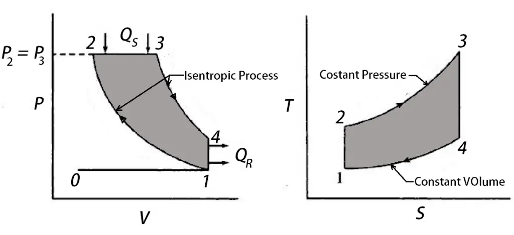
Jun 3, 2019 — Brayton Cycle - pV - Ts Diagram. The Brayton cycle is often plotted on a pressure volume diagram (pV diagram) and on a temperature-entropy ... Draw P-V and T-S diagram of dual combustion cycle. Last Answer : Dual combustion cycle: 1-2 Isentropic compression of air 2-3 the combustion of fuel at constant volume. 3-4 the combustion of fuel at constant pressure 4-5 Isentropic expansion during which work is done by the system.
Plot the T-s diagram for the cycle. Problem 9-93. An ideal Brayton cycle with regeneration has a pressure ratio of 10. Air enters the compressor at 300 K and the turbine at 1200 K. If the effectiveness of the regenerator is 100 percent, determine the net work output and the thermal efficiency of the cycle.
Brayton cycle ts diagram
Ts diagram of the Brayton cycle with reheat and regeneration. As discussed, the maximum temperature is limited by metallurgical consideration. Still, to deliver more heat at a temperature close to the peak of the cycle, the gas can be reheated in a reheater. Read: Full notes on Ericson Cycle with PV and TS diagram #4 Joules cycle. Joules Cycle is also known as the Brayton cycle. It is a thermodynamic cycle named after George Brayton. It describes the workings of a constant-pressure heat engine. Consists of two constant pressure and two adiabatic processes. Read: Full notes on Joules cycle with PV ... The area under the T-s diagram is proportional to the useful work and thrust generated by the engine. The p-V diagram for the ideal Brayton Cycle is shown here: The Brayton cycle analysis is used to predict the thermodynamic performance of gas turbine engines.
Brayton cycle ts diagram. The Air Standard Diesel Cycle Is Shown On P V And T S Diagrams Respectively This Is The Ideal Cycle For The Diesel Engine Wh Thermodynamics Cycle Engineering . Pin On Termodynamika . Ideal Brayton Cycle T S Diagram Nasa Google Search Brayton Cycle Diagram Nasa . Diesel Cycle Process With P V And T S Diagram Cycle Process Cycle Diagram ... A T-s diagram of an ideal, transcritical CO 2 cycle is shown in figure 21. The cycle operates over a smaller temperature range than Joule-Brayton cycles, with typical top temperatures in the range 95 °C-150 °C and bottom temperatures in the range −25 °C to 25 °C. An air standard diesel cycle has a compression ratio of 20 and an isobaric expansion ratio ( V 3 / V 2 ) of 2. Pressure and temperature at the start of the compression process are P 1 = 1 bar and T 1 = 350 K. Find the cycle thermal efficiency. Compare the result with the Carnot efficiency. Given the... Download scientific diagram | T-S diagram for a simple Brayton Cycle from publication: Improvement of Gas Turbine Power Plant Performance: A Review | Gas ...
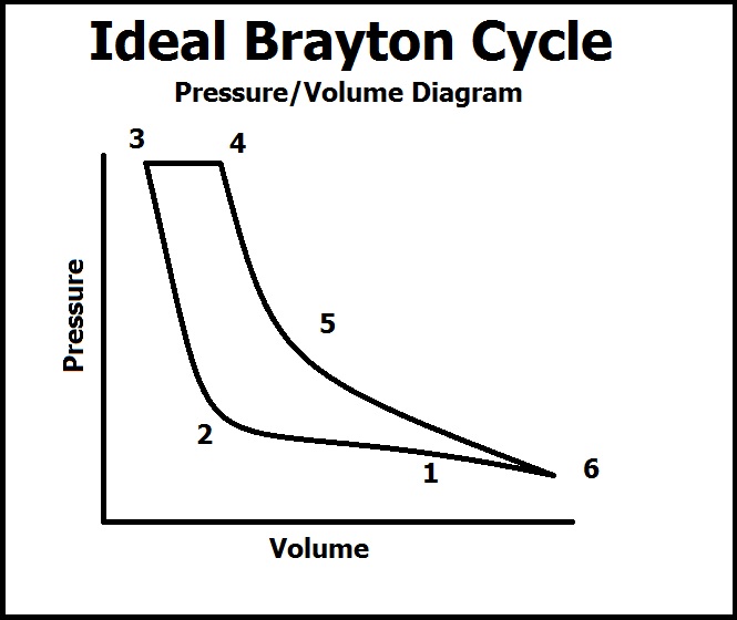
Diesel cycle PV and TS diagram: The diesel cycle can be plotted on PV and TS plot as shown below, Each process of the diesel cycle is described as, Process 1-2:- Isentropic compression. In this process, the charge taken during suction stroke is compressed adiabatically from volume `V_{1}` to `V_{2}`. What is bell coleman cycle? Bell coleman air refrigeration cycle is reverse brayton cycle which consists of the two isentropic processes and two constant pressure (Isobaric) processes which is used to absorb heat from the low-temperature cabin and reject it to the high-temperature cabin.; This cycle is used for the both heating and cooling purpose and uses air as an refrigerant (working fluid). Aug 15, 2020 · The Brayton Cycle can then be described quantitatively in the gas turbine engine of a jet by two diagrams, the Temperature/Entropy Diagram and the Pressure/Volume Diagram. Temperature/Entropy Diagram In this diagram, we see that there are 8 processses to describe the Brayton cycle in terms of temperature, entropy, and pressure. A simple ideal Brayton cycle operates with air as the working fluid. Initially air is at100 kPa. The maximum temperature is 727 o C during the cycle. The maximum pressure is 2000 kPa during the cycle. 330 kJ/kg of heat is transferred into the system during the constant-pressure heat addition process. Determine (a) Draw a T-s diagram to show the ...
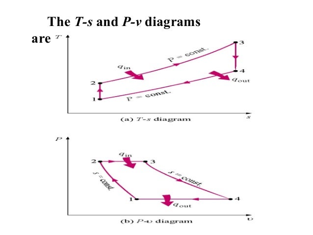
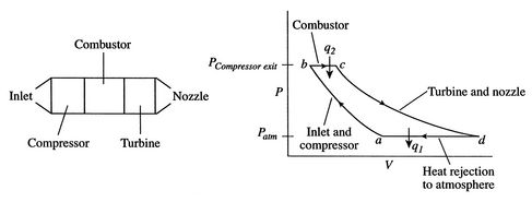
Rankine cycle study notes are vital in Mechanical Engineering, especially if you are preparing for the GATE 2022 exam.We have listed the complete study notes for your GATE ME exam preparation below. The Rankine Cycle is a part of the Thermodynamics chapter important for the GATE, SSC JE Mechanical, ESE, BARC, ISRO, and other mechanical engineering exams. The P-v and T-s diagrams of an ideal Brayton cycle are shown on the left. In an ideal Brayton cycle, heat is added to the cycle at a constant pressure ... May 2, 2019 — Brayton Cycle | Efficiency, P-V & T-S Diagrams | Heat & Work Table · Brayton cycle (or Joule Cycle) is a thermodynamic cycle upon which a Gas ... The Joule-Brayton (or gas-turbine) cycle comprises two adiabatic and two isobaric processes and uses an ideal gas as the working fluid. A simplified (reversible) representation on the temperature-entropy diagram is shown in Fig. 1 (left-hand cycle). The cycle is traversed in the anticlockwise sense during the charge (heat-pump) phase and clockwise during the discharge (heat-engine) phase.
Brayton Cycle Ts Diagram - General Wiring Diagram
In the T-S diagram, the temperature (T) will decrease from T3 to T4 and the entropy (S) will remain constant. From 4-1: Gas released to atmosphere From 3 to 4, the air from the turbine will be released into the atmosphere. Also, air will be drawn from the atmosphere to the compressor and the whole cycle will repeat again.

EFFECT OF INTERCOOLING ON BRAYTON CYCLE - Mechanical engineering concepts and principles
P-v and T-s Diagram of Diesel Cycle. Let the engine cylinder carry m kg of air at point 1. at this point let P1 and T1 and V1 be the pressure, temperature and volume of the air. Following are 4 stages of an ideal diesel cycle. The ideal diesel cycle consists of two adiabatic, constant pressure and constant volume processes.

green and white labeled box
How to plot the PV and TS diagram of an Brayton Cycle. I only have Temperature and Pressure values. Follow 101 views (last 30 days) Show older comments. Ayan Atal on 22 Jul 2021. Vote. 0. ⋮ . Vote. 0. Answered: Shubham Khatri on 30 Jul 2021 Accepted Answer: Shubham Khatri.

BRAYTON CYCLE WITH REHEATING - Mechanical Engineering Professionals
Based on the improved Claude precooling cycle combined with Joule-Brayton refrigeration cycle, a hydrogen liquefaction process with high efficiency and mixed refrigerants is developed. Four independent refrigeration cycles with nitrogen and three different mixed refrigerants are used. By this process, 288.92 tons gaseous hydrogen (25 °C, 21 bar) can be transferred into liquid hydrogen (− ...

T-s Diagram of a Brayton Cycle with Regeneration
May 22, 2019 · Ts diagram of the Brayton cycle with reheat and regeneration. As was discussed, the maximum temperature is limited by metallurgical consideration, but in order to deliver more of the heat at a temperature close to the peak of the cycle the gas can be reheated in a reheater.
6.9 Effect of Departures from Ideal Behavior
Brayton cycle is explained along with efficiency, T-s, and P-v, diagrams, etc. This article consists of many easy diagrams, explanations, formulas, and examples to clear the basic idea about the Brayton cycle.
Gas Refrigeration Cycle Ts Diagram - Diagram Media
The temperature of the steam at the turbine inlet is 300 C and the mass flow rate of steam through the cycle is 35 kg/s. Show the cycle on a T-s diagram with respect to saturation lines and determine a) the thermal efficiency of the cycle and b) the net power output of the power plant.

Brayton Cycle | Efficiency, P-V & T-S Diagrams | Heat & Work Table
5-1: T-s diagram and major components for Carnot refrigerator. Why is the reversed Carnot cycle impractical? ... A Brayton cycle that is driven in reverse direction is known as the reverse Brayton cycle. Its purpose is to move heat from colder to hotter body, rather than produce work. This cycle is also known as the gas refrigeration cycle or ...
Improving an Air-Standard Power Cycle
Brayton Cycle – pV – Ts Diagram ... In 1872, an American engineer, George Bailey Brayton, advanced heat engines study by patenting a constant pressure internal ...

Gas Turbine Power Plant Regeneration-Reheating-Intercooling : Mechanical Engineering
4-1 const. pressure heat rejection (exhaust). Fig. 2: T-s and P-v diagrams for ideal Brayton cycle. Thermal efficiency for the Brayton cycle is:.7 pages

How does a jet engine work? Brayton thermodynamic cycle and efficiencies | Engineering360
Schematic representation of an air standard Brayton cycle. Brayton cycle on (a) P-v diagram (b) T-s diagram. Processes: -. 1-2: isentropic compression.

11: T-s diagrams for Joule-Brayton cycle based PHES systems proposed by... | Download Scientific ...
Adiabatic Process Diagram. Here are a number of highest rated Adiabatic Process Diagram pictures on internet. We identified it from reliable source. Its submitted by government in the best field. We acknowledge this kind of Adiabatic Process Diagram graphic could possibly be the most trending subject next we part it in google help or facebook.

Obtained diagram entropy (Ts) of Brayton Cycle | Download Scientific Diagram
Ts diagram of Brayton cycle with reheat, inter-cooling, and heat regeneration. Reheat, Inter-cooling and Regeneration in Brayton Cycle. As was discussed, reheat and inter-cooling are complementary to heat regeneration. By themselves, they would not necessarily increase the thermal efficiency, however, when inter-cooling or reheat is used in ...
Brayton cycle
Process 1-2 = Adiabatic compression of gas. Process 2-3 = Heat addition at a constant pressure.. Process 3-4 = Adiabatic expansion of gas in the turbine.. Process 4-1 = Heat rejection at constant pressure.. Explanation of P-V and T-S diagram of Closed cycle gas turbine Process 1-2 The air enters the compressor and is compressed adiabatically hence for processes 1-2 you can see a rise in ...
What is the Brayton cycle? - ExtruDesign
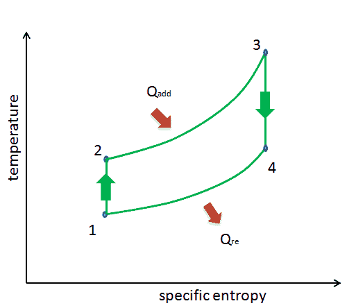
The ideal Brayton cycle is made up of four internally reversible processes, T-s diagram. 1-2 Isentropic compression (in a compressor) 2-3 Constant pressure heat addition 3-4 Isentropic expansion...

Represent ‘Brayton Cycle’ on P-V and T-S diagram ...
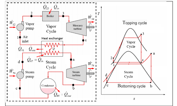
This cycle is a symbiosis of the Brayton (simple cycle gas turbine) cycle and the Rankine (steam turbine) cycle. Figure 2. Typical efficiencies of various types of plants [3] Figure 2, above, shows the efficiency of the power plant depending on the type of cycle. The power plants referenced are: the simple cycle gas turbine (SCGT) plants with ...
Analyze Each Given Cycle And Then The Combined Bra... | Chegg.com
THE BRAYTON CYCLE WITH INTERCOOLING, REHEATING, AND REGENERATION A gas-turbine engine with two-stage compression with intercooling, two-stage expansion with reheating, and regeneration and its T-s diagram. For minimizing work input to compressor and maximizing work output from turbine: Comparison of work inputs to a single-stage compressor (1AC …

2: T-S diagram of a Joule-Brayton cycle. | Download Scientific Diagram
Siklus Carnot - Tahapan, Mekanisme, Daya Guna & Contoh Soal - Untuk pembahasan kali ini kami akan mengulas mengenai Siklus Carnot yang dimana dalam hal ini meliputi tahapan, mekanisme, daya guna dan contoh soal, nah agar dapat lebih memahami dan dimengerti simak ulasan selengkapnya dibawah ini. Sebelum membahas siklus Carnot terlebih dahulu ...
What is Brayton Cycle - Gas Turbine Engine - Definition
Carnot Cycle TS Diagram. A Carnot Cycle, when plotted on a TS (Temperature-Entropy) plot, looks as shown below. Here again, the work done by the engine is represented by the area bounded by the complete path of the TS plot.

T-S diagram of the closed Brayton cycle. | Download Scientific Diagram
The Brayton cycle is a thermodynamic cycle that describes the operation of certain heat engines that have air or some other gas as their working fluid. The original Brayton engines used a piston compressor and piston expander, but modern gas turbine engines and airbreathing jet engines also follow the Brayton cycle.

time lapse photography of two bikers
On this page we discuss the Brayton Thermodynamic Cycle which is used in ramjets and scramjets. The figure shows a T-s diagram of the Brayton cycle. Using the turbine engine station numbering system , we begin with free stream conditions at station 0 . In cruising flight, the inlet slows the air stream to compress it to station 2 conditions.

P-V and T-S diagrams of a standard air Brayton cycle | Download Scientific Diagram
Also draw p-h and T-s diagram for the same. 0 0 SMDARJI Tuesday, January 26, 2021 Vapour Compression Refrigeration Syestem. A Schematic diagram of simple vapour compression refrigeration(VCR) cycle is shown in fig. ... The cycle is represented on T-s and P-h diagram shown in following fig.

Joule-Brayton cycle on T-s plot. | Download Scientific Diagram
a) Choose the suitable thermodynamic cycle "Brayton Cycle" b) Draw pv and Ts diagram and label it c) Calculate the power required by the compressor d) Determine the pressure and the temperature at the turbine exit e) Compute the power produced by the turbine f) Available specific work g) The thermal efficiency.

Brayton Cycle | Efficiency, P-V & T-S Diagrams | Heat & Work Table
GATE Thermodynamics Question Paper 2022. October 21, 2021. October 17, 2021 by Somya. GATE Thermodynamics Question Paper: Download the GATE Thermodynamics Question Paper in pdf format. Today we're offering GATE Question Papers of XE-E: Thermodynamics. On this page, you may get GATE Thermodynamics Question Papers from modern-day to past few years.

Otto Cycle Ts Diagram — UNTPIKAPPS
The area under the T-s diagram is proportional to the useful work and thrust generated by the engine. The p-V diagram for the ideal Brayton Cycle is shown here: The Brayton cycle analysis is used to predict the thermodynamic performance of gas turbine engines.

4. Process of a CO2 supercritical Rankine cycle on T-s diagram... | Download Scientific Diagram
Read: Full notes on Ericson Cycle with PV and TS diagram #4 Joules cycle. Joules Cycle is also known as the Brayton cycle. It is a thermodynamic cycle named after George Brayton. It describes the workings of a constant-pressure heat engine. Consists of two constant pressure and two adiabatic processes. Read: Full notes on Joules cycle with PV ...
Case Study: Brayton Cycle - Chemwiki
Ts diagram of the Brayton cycle with reheat and regeneration. As discussed, the maximum temperature is limited by metallurgical consideration. Still, to deliver more heat at a temperature close to the peak of the cycle, the gas can be reheated in a reheater.
Ramjet Thermodynamic Cycle - Brayton Cycle
3.7 Brayton Cycle

Ideal Brayton Cycle and Actual Gas Turbine Cycle on T - s Diagram
T -S Diagram illustrating the stages in Joule-Brayton Cycle [11] | Download Scientific Diagram

white animal skull on white surface

T-s and P-v Diagrams for the Ideal Brayton Cycle

Ch9, Lesson E, Page 13 - Deviations from the Ideal AS-Brayton Cycle

The StarRotor engine uses the Brayton cycle - Democratic Underground

Temperature-Entropy (T-s) diagram for MiTi's 8 kW engine Brayton cycle... | Download Scientific ...

Example 9E - 2: Performance of a "Real" Brayton Cycle

Thermodynamics eBook: Brayton Cycle with Intercooling

T-s diagram of the combined power cycle showing the ...

T-S diagram of recompression S-CO 2 Brayton cycle with MCIC. | Download Scientific Diagram

Thermodynamics eBook: Brayton Cycle with Intercooling

P-V and T-S diagrams of a standard air Brayton cycle | Download Scientific Diagram
Comments
Post a Comment