41 refrigerator pv diagram
adiabatic, isochoric expansion (vertical line on PV diagram) T, b.p. ~ P no work done W = 0; evaporator cold liquid from the expansion valve boils inside the cold box, absorbing latent heat isothermal, isobaric boiling (horizontal line on PV diagram) low temperature T (cold) latent heat of vaporization Q (cold) indicator diagram. vapor ... The cycle of an ideal gas Carnot refrigerator is represented by the pV diagram of . It is a Carnot engine operating in reverse. The refrigerator extracts heat from a cold-temperature reservoir at when the ideal gas expands isothermally.
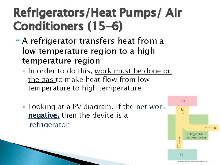
heat pump/refrigerator and be able to differentiate between the efficiency and the coefficient of performance. ... engine depicted using heat reservoirs minus the work done by the engine depicted using a PV diagram (i.e., your answer will be negative if the engine on the right does more work). Answer: 2J - 2J = 0 J.

Refrigerator pv diagram
A convenient way to visualize these changes in the pressure and volume is by using a Pressure Volume diagram or PV diagram for short. Each point on a PV diagram corresponds to a different state of the gas. The pressure is given on the vertical axis and the volume is given on the horizontal axis, as seen below. Refrigeration cycle PV diagram. click on images to expand the view. C → D: low-pressure vapor refrigerant flows into the compressor suction and discharges into compressed high-pressure vapor. D → A: pressurized refrigerant vapor condenses in the liquid state at constant pressure, rejection of heat to the environment. 3.5 Carnot cycle: p-V diagram and T-S diagram. In what follows we discuss one of the most important concepts of thermodynamics, the Carnot cycle.
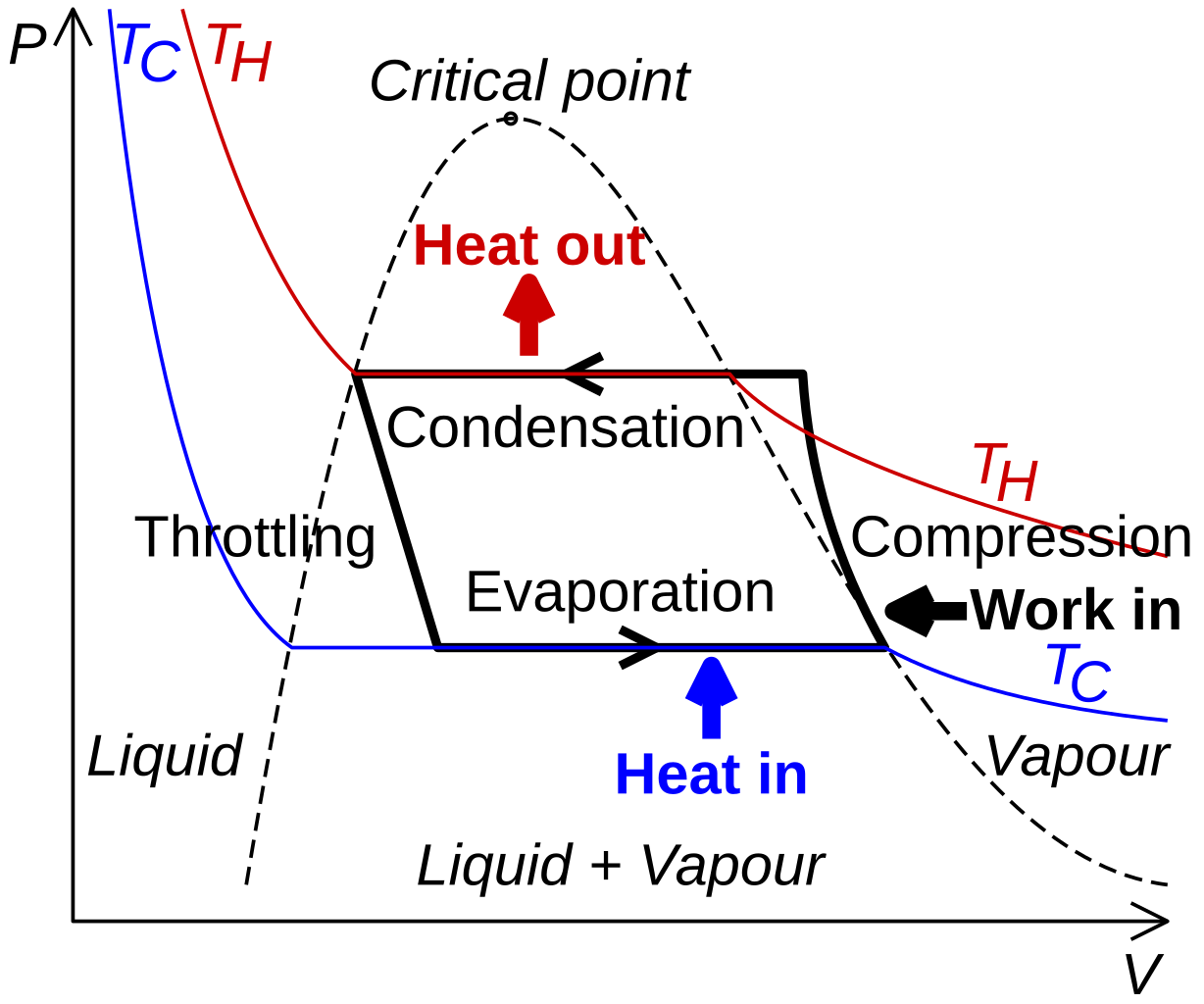
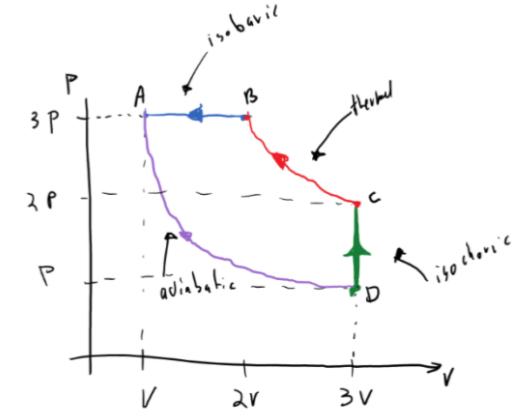
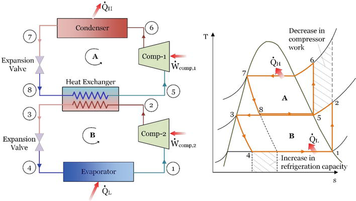
Refrigerator pv diagram. The COP of the refrigerator, Practical Vapour compression refrigeration cycle (a) schematic diagram (b) T-s diagram . Application of the first law of thermodynamics to the control volume compressor, condenser, throttle and evaporator gives (W s) compressor =h 2-h 1 . Q H =h 2-h 3 . h 3 =h 4 . and Q L =h 1-h 4 . The COP of the refrigerator is ... • Two significant effects are apparent from the Ts diagram: (1) for the single cycle - the compressor work is increase by area 2->a->6->5->2. (2) there is a decrease in the refrigeration capacity when a single unit is used => 4->b->d->c->4. • For the double-cascade system shown, it is important that the triple-state The internal combustion engine is a heat engine.It’s working principle is based on the variation of pressure and volume inside the engine’s cylinders. All heat engines are characterized by a pressure-volume diagram, also known as pV diagram, which basically shows the variation of the pressure in the cylinder function of its volume, for a complete engine cycle. P-V Diagram for a refrigerator The P-V diagram shown below is over-simplified, showing two adiabatic processes and two isobaric (constant pressure) processes but neglecting the two changes of state that occur. This gives you the general flavor of the cycle, however.
The P-v diagram of the reversed Carnot cycle is shown on the left. The Carnot Refrigerator and Heat Pump A refrigerator or a heat pump that operates on the reversed Carnot cycle is called a Carnot refrigerator or a Carnot heat pump. The coefficient of performance (COP) of reversible or irreversible refrigerator or heat pump is given by represented on a PV diagram. A refrigeratoris a heat engine, run in reverse. W + Qc= Qh Another form of the Second Law of Thermodynamicsis that It is not possible to make a heat engine whose only effect is to absorb heat from a high-temperature region and turn all that heat into work. That is, it is not possibleto Refrigerators can also be described as cycles on a PV diagram and gas in a refrigerator should absolutely undergo a cyclic process, that way it starts and ends at the same state so you can keep doing it cycle after cycle after cycle. It's the same reason why you want engines to be cyclic processes. Air Refrigerator Working On Bell-Coleman Cycle with PV and TS Diagram (Reversed Brayton or Joule Cycle) Mecholic Refrigeration and Air Conditioning Fig shows a schematic diagram of Bell-Coleman refrigerator (reverse Brayton or joule cycle). This refrigeration system components consists of a compressor, cooler, Expander, and refrigerator.
refrigerator overall heat transfer resistance may change more than 10 percent in the two-phase region of the evaporator and more than 20 percent in the superheated region. In addition to being more accurate than the constant conductance model, the variable conductance model is also more flexible. When the constant conductance model is used a To improve the energy efficiency of a grid-connected PV-Battery configuration residential system that has a refrigerator as load, it is essential to understand the main electrical diagram of the current available refrigerators. Link back to: arXiv, form interface, contact. Browse v0.1 released 2018-10-22 Feedback?. If you have a disability and are having trouble accessing information on this website or need materials in an alternate format, contact web-accessibility@cornell.edu for assistance.web-accessibility@cornell.edu for assistance. ... diagram | Pressure-volume diagram for a typical refrigeration cycle from publication: Design, fabrication and performance analysis of solar PV air ...
Stirling Refrigeration Cycle (a) P-V diagram (b) T-S diagram ...
as a supplement, the engine was run as a refrigerator by using a rotary tool to turn the flywheel of the engine. A small, but measurable, temperature difference developed across the body of the engine. Stirling engines have long been used as in-class demon - strations and, 1,2 in some cases, P-V diagrams have been con -
Design of Vapor-Compression Refrigeration Cycles
Aug 28, 2020 · File:Refrigeration PV diagram.svg. Size of this PNG preview of this SVG file: 512 × 427 pixels. Other resolutions: 288 × 240 pixels | 576 × 480 pixels | 921 × 768 pixels | 1,228 × 1,024 pixels | 2,456 × 2,048 pixels.
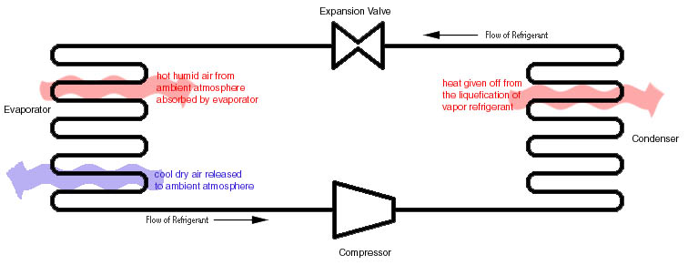
2.972 How A Compression Refrigeration System Works
Aug 31, 2016 - Refrigeration PV diagram - Vapor-compression refrigeration - Wikipedia, the free…

Mechanism And Working Of A Vapour Compression Refrigeration ...
The P-h diagram is another convenient diagram often used to illustrate the refrigeration cycle. The ordinary household refrigerator is a good example of the application of this cycle. Results of First and Second Law Analysis for Steady-Flow Component Process First Law Result Compressor s = const. Wmhh () in =−21

Heat Engines
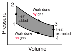
Nov 26, 2014 · Homework Statement I have a rectangular PV diagram of a heat engine. Like this one: I have to show why this cannot work in reverse as a refrigerator. Homework Equations U = 0.5fnRT (U = internal energy, f = degrees of freedom, n = number of moles of gas, R = ideal gas constant, T =...
Experimental Study on P-V diagram and motion curve of suction ...
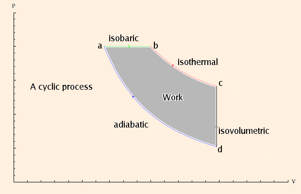
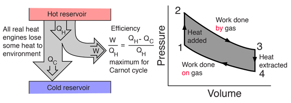
For any kind of heat engine or refrigerator (reverse heat engine), the processes involved form a cycle on the P-V graph. The work is the area of the enclosed region on the graph. The diagram for a refrigerator is a little more complicated than this because of the two phase changes involved, but this is basically what it looks like:
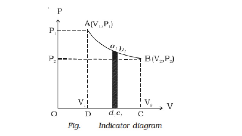
Indicator diagram (P-V diagram)
The area enclosed within a pV curve is A.the work done by the system during one complete cycle. B. the work done on the system during one ... • The gas in a refrigerator can exhaust heat QH to the hot reservoir only if the gas temperature is higher than the hot-reservoir temperature TH. Heat energy is
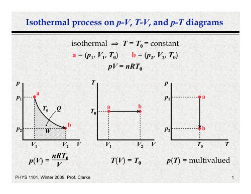
Isothermal process on p-V, T-V, and p-T diagrams
refrigerator or heat pump that operates on the reversed Carnot cycle is called a Carnot refrigerator or a Carnot heat pump. Fig. 5-1: T-s diagram and major components for Carnot refrigerator. The reversed Carnot cycle is the most efficient refrigeration cycle operating between two specified temperature levels. It sets the highest theoretical COP.

Heat Engines Heat Pumps - ppt video online download
May 12, 2020 · Stirling cycle was devised by Stirling, which consists of two isothermal processes and two constant volume processes. The last two processes are performed with the help of a refrigerator to make this cycle reversible. The p-v and t-s diagram of this cycle are shown in the figure. Let us now consider the four stages of the Stirling cycle.
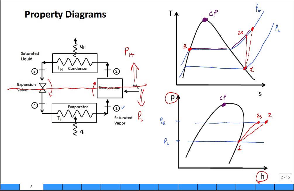
Property diagrams TS and PH for refrigeration 2
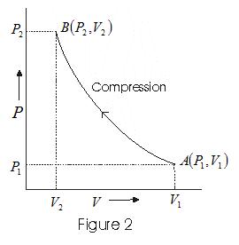
Fig (1) and fig (2) shows the p-v and T-s diagram of a refrigeration system working on reversed Carnot cycle. The process involved in reversed Carnot cycles are as follows 1-2. isentropic compression process During this stage, air is compressed isentropically. Pressure and temperature increases, the specific volume of decreases.
P-V and T-S Diagrams
A concise, expert explanation of the inner workings of a refrigerator with a detailed diagram. Refrigerator Parts Diagram ©Don Vandervort, HomeTips. Refrigerators and freezers (as well as air conditioners, heat pumps, and other appliances that produce “cold”) use basic refrigeration principles to extract heat from the air.
chapter 6
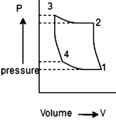
The figure shows the pV diagram of a refrigerator Adiabats Stage B During which stages is heat added to the gas? During which is heat removed from the gas? During which stages is work done on the gas? During which is work done by the gas? Circle the answers that complete the sentence: The temperature of the hot reservoir must be i. > the ...

Improvement on energy consumption of a refrigerator within PV ...
This web page is an interactive physics simulation on the cycles a refrigerator goes through. The user can see that this cycle requires work to move heat, as compared to an engine moving heat to do work. This is part of a collection of similar simulation-based student activities. Please note that this resource requires Java Applet Plug-in. http ...
Notes for Calculus-based Physics
The question doesn't say it is a reversible heat engine. All it says is that we have a rectangular cycle on a PV diagram, and we are trying run it counterclockwise to make a refrigerator (unlike the image where it's running in clockwise direction).

Carnot heat pump (or Carnot refrigerator)
3.5 Carnot cycle: p-V diagram and T-S diagram. In what follows we discuss one of the most important concepts of thermodynamics, the Carnot cycle.
Impossible refrigerator (thermodynamics and PV diagrams ...
Refrigeration cycle PV diagram. click on images to expand the view. C → D: low-pressure vapor refrigerant flows into the compressor suction and discharges into compressed high-pressure vapor. D → A: pressurized refrigerant vapor condenses in the liquid state at constant pressure, rejection of heat to the environment.
What is the T-s diagram for the Carnot refrigeration cycle ...
A convenient way to visualize these changes in the pressure and volume is by using a Pressure Volume diagram or PV diagram for short. Each point on a PV diagram corresponds to a different state of the gas. The pressure is given on the vertical axis and the volume is given on the horizontal axis, as seen below.
Chapter 10: Refrigeration Cycles
File:Refrigeration PV diagram.svg - Wikimedia Commons

Stirling Cycle - Efficiency Explaination with P-v and T-s Diagram
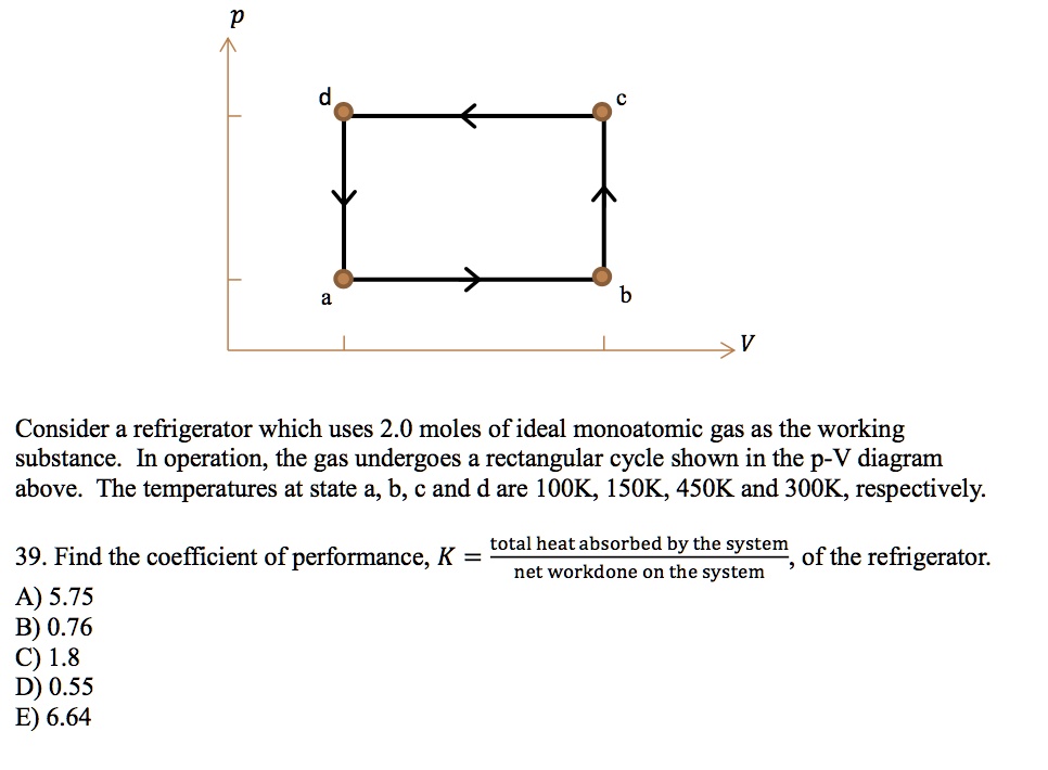
SOLVED:Consider a refrigerator which uses 2.0 moles of ideal ...
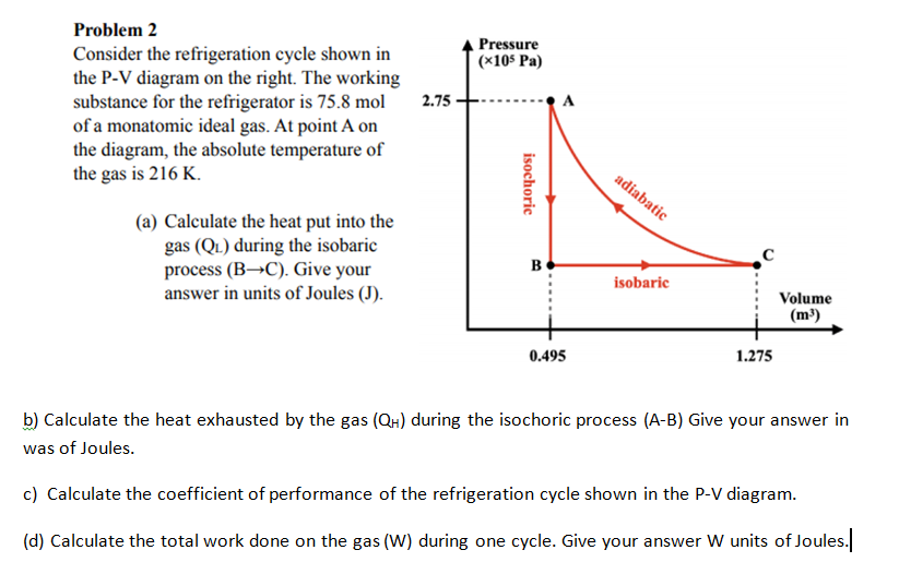
Solved Pressure (x105 Pa) Problem 2 Consider the | Chegg.com

Bell Coleman Cycle with PV and TS diagram - Mechanical Walkins
Heat Engines

Bell Coleman Cycle with PV and TS diagram - Mechanical Walkins
Heat Engines
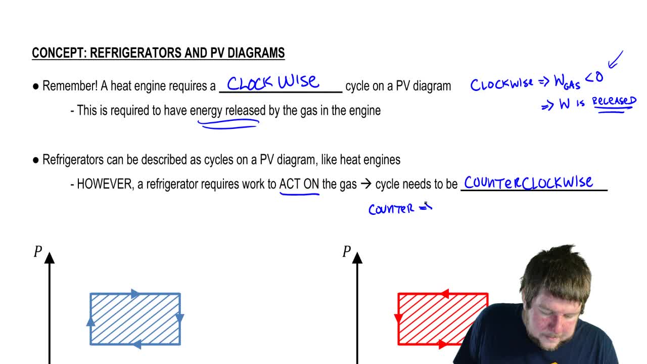
Refrigerators & PV Diagrams - Physics Video | Clutch Prep

Vapor Compression Refrigeration System | Basic, Working ...

Heat Engine Cycle
Reverse Carnot Cycle - Vapour Refrigeration Cycles Questions ...
Heat engines and the second law
The Laws of Thermodynamics Chapter 15 What is
P-V Indicator Diagram with solved Examples

How does a Refrigeration Cycle work? | What is Refrigeration?

Solved The Stirling cycle, represented on the PV diagram ...
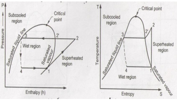
Explain vapour compression refrigeration cycle on T-S and p-h ...
Solved Refer to the PV diagram below showing the | Chegg.com

Chapter 3a - The First Law - Closed Systems - Energy (updated ...
Heat Engines
REFRIGERATION
Energy and Exergy Analysis of Refrigeration Systems | IntechOpen
Comments
Post a Comment