41 motorcycle regulator rectifier wiring diagram
All about motorcycleJHAY'D MECHANIC May 21, 2020 - Motorcycle Voltage Regulator Schematic Diagram and Dnepr Voltage Regulator Wiring Diagram - Wiring Diagrams Folder - 15+ Motorcycle Voltage Regulator Schematic Diagram .Motorcycle Voltage Regulator Schematic Diagram and Dnepr Voltage Regulator Wiring Diagram - Wiring Diagrams Folder - Wiringg.net
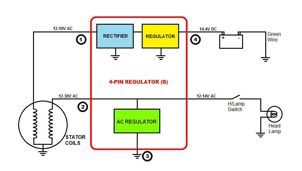
The regulator part of the regulator-rectifier is used to regulate the output-voltage (to the battery) to the 14.4 Vdc that is needed. The Permanent Magnet Generator System A generator on a bike is producing this electrical power because it has a copper wire winding on the stator (the static part of the generator) that is located inside a ...

Motorcycle regulator rectifier wiring diagram
Motorcycle Regulator Rectifier Wiring Diagram. By grandcaret | June 13, 2019. 0 Comment. Understanding motorcycle voltage regulator wiring homemade circuit projects atv gy6 50 150cc scooter 4 wires rectifier boat at affordable s free shipping real reviews with photos joom building a for electronics forums tester universal honda cg125 150 zj125 ... Many Rick's Motorsport Electrics Rectifier/Regulators eliminate what is commonly referred to as a "signal wire" on original equipment (OE) pieces. For example, on a 1981 Kawasaki KZ440, there are 5 wires going to the OE part: 2 yellow wires (AC inputs), white/red (DC "+" output), black/yellow (DC "-" output), and a brown wire. 4 wire voltage regulator wiring diagram adding a battery to my startv bike rectifier lawn mower g regulater gy6 50cc 150cc moped scooter atv understanding motorcycle half wave 12v pin upgrade 110cc kazuma falcon on fa25 b9b 2 3 and rectifiers 6c2 charging problems conversion pit headlight problem mini no for kz650 replacement 6 ac.
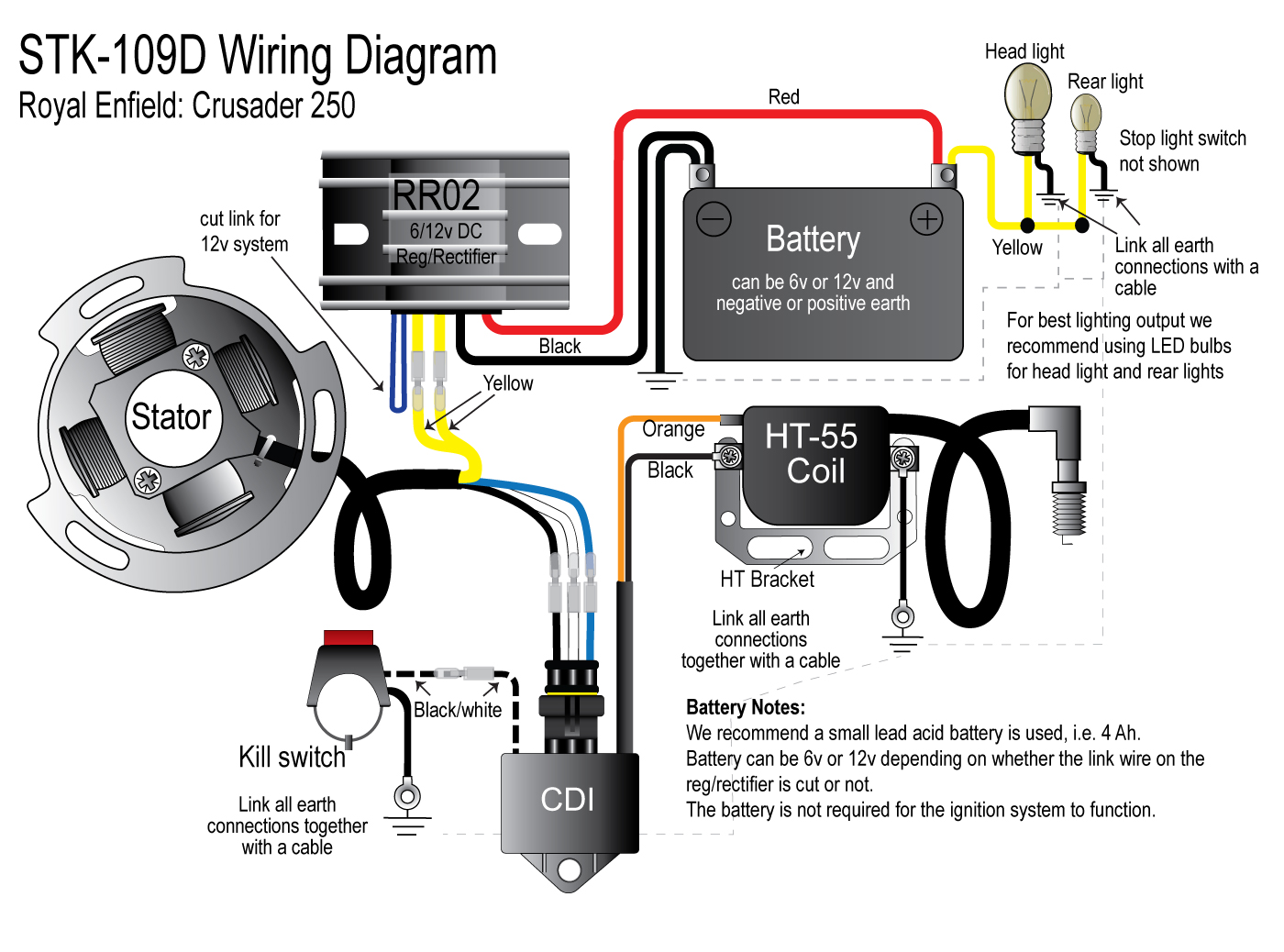
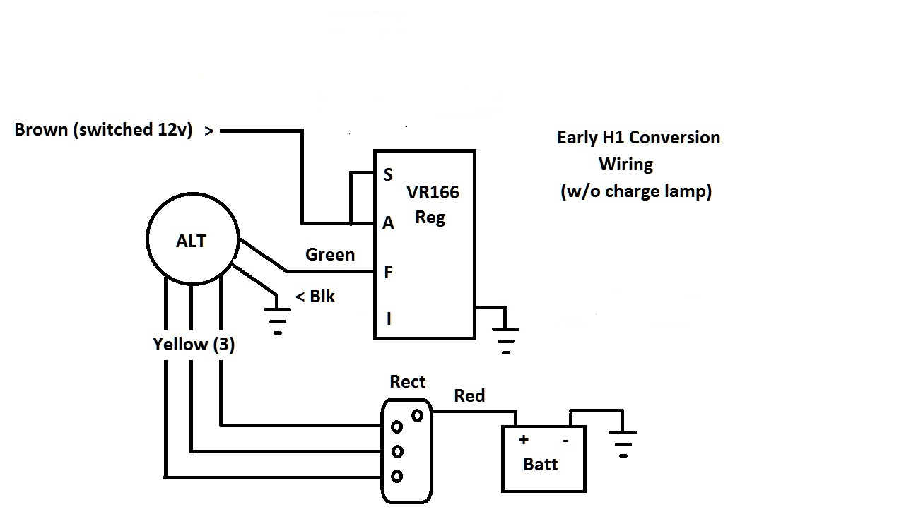
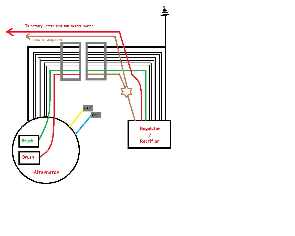
Motorcycle regulator rectifier wiring diagram. A regulator/rectifier combo unit to replace the separate units on your old charging system. New points and condensers OR an electronic ignition and proper coils. Blade-style fuse box. Rebuilt/cleaned starter motor. Motorcycle Wire Gauges. Most motorcycles use: 16 to 18 gauge wire for the primary wires and wires to controls, lights, etc. 2 phase 5 wire motorcycle regulator rectifier wiring diagram pdf. The R2-55a6 rectifier is a universal fit 6 wire rectifier like the one at the top of the page but it has an additional set of diodes for a half wave positive output for bikes that require this. There should be a wiring harness 5 wires or so coming from the alt housing on left ... 12v Three Phase Regulator Rectifier Fitting Instructions. Simply connect the 3 output wires from the 3 phase stator to the 3 yellow AC wires of your The Red + and the Black - then connect into your motorcycle wiring. (see diagram below) regulator rectifiers you must use resisted spark plugs as circuitry is sensitive. Dan's Motorcycle "Wiring Diagrams". Reading Wiring Diagrams. "And God said, Let there be light: and there was light. And God saw the light, that it was good: and God divided the light from the darkness." Genesis 1:3-4. ¶ Every motorcycle has a Wiring System. Every one of them, bar none. Without a Wiring System there will be no light.
2 phase 5 wire motorcycle regulator rectifier wiring diagram pdf. We ve even included standard wire colours where appropriate. Lamberts bikes motorcycle part wiring diagrams. Simply plug the connector onto the 5 pins row and make sure that the pin assignments and wire assignments are matched correctly. M 3 2 2 2 phase 5 wire. In this case, the rectifier regulator will come with wire leads only and you will need to hard wire it. Before replacing your rectifier regulator, be sure to read these instructions & check the integrity of all your electrical connectors. Item may vary from image. Must-do Tips BEFORE installing a Rectifier/Regulator. Check the AC output of the ... Details about Universal 4 Wire 2 Phase Motorcycle Regulator Rectifier 12V DC Bike Scooter. average based on 2 product ratings. 5. 2. 4. 0. 3. 0. 2. 0. 1. 0. 1x 4 Wire Regulator Rectifier + 1x Wiring Diagram. Wiring your bikes charging circuit has never been so easy! The heat sink on these units is electrically isolated from the 5/5(2). Regulator rectifier diagram here you are at our site this is images about regulator rectifier diagram posted by maria nieto in wiring category on may 08 2019. Provided below is an online pdf document for lamberts bikes 3 phase 6 wire regulator rectifier wiring diagram. This is the ultimate guide to the humble motorcycle regulator rectifier.
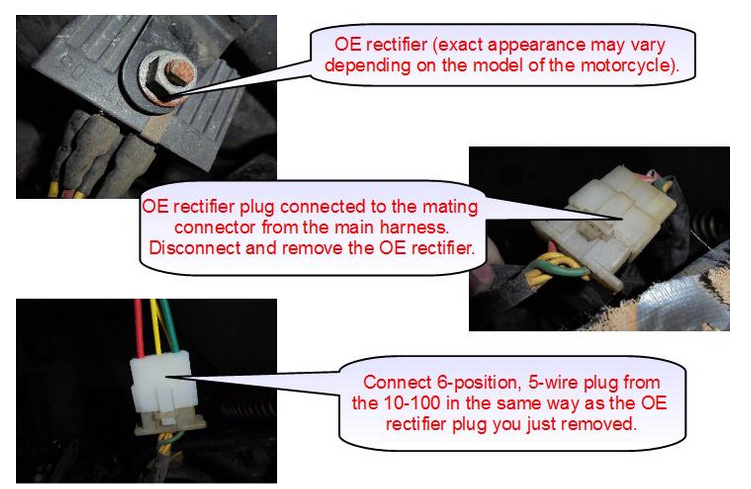
Rectifier Regulator Wiring Diagram - 12v rectifier regulator wiring diagram, atv regulator rectifier wiring diagram, honda regulator rectifier wiring diagram, Every electric structure consists of various distinct components. Each part should be placed and linked to different parts in particular way. Otherwise, the arrangement will not work as it ought to be. The 10 100 rectifier plugs into the harness at the same location as the oe rectifier. Part of lamberts bikes online library of pdf motorcycle manuals wiring diagrams and technical guides. Simple Harley Wiring Diagram Wiring Diagram Data Schema This article is made due to many queries after the post about deadbug prototyping so ive […] Custom wiring diagrams using Oregon motorcycle Parts regulator/rectifier units Honda SOHC fours up to 1978 KZ400 and KZ750 twins (late model with permanent magnet alternator) Pre 1978 Honda singles and twins Yamaha twins DS7, R5 RD250, RD350 & XS650 (original equipped with a separate regulator and rectifier) This is an updated version fixing 3) 4-pin Regulator (A): This type may be found on some motorcycles. In this system, both the ends of the winding go to the Rectifier section which converts AC to DC voltage and then the Regulator section regulates to 14.4V as discussed above. 4) 4-pin Regulator (B): This is the most common type found on motorcycles with single-phase winding.
3 Wire Rectifier Regulator Wiring Diagram - Wiring Forums
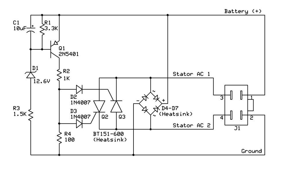
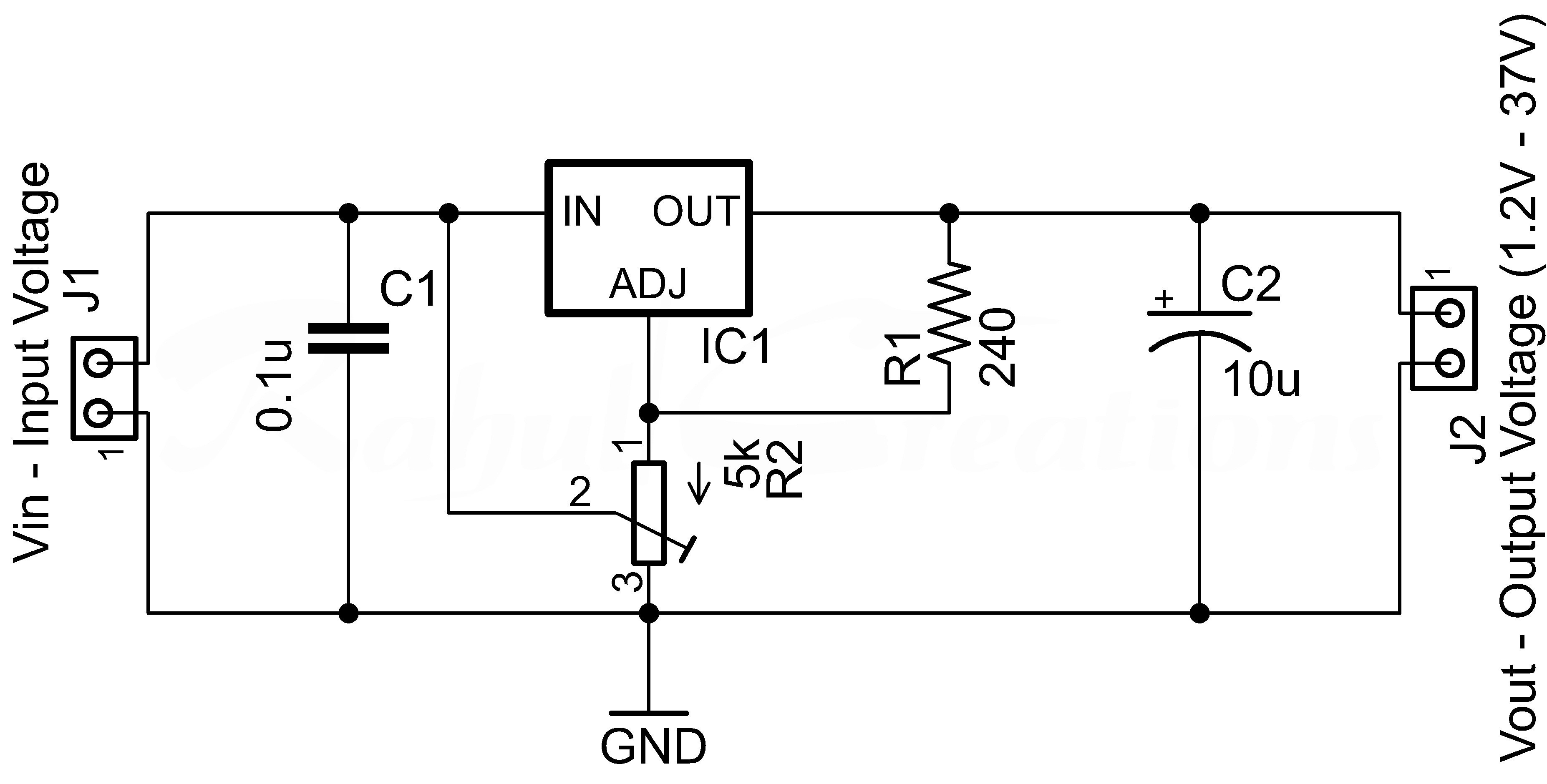
The Design. The proposed 3 phase motorcycle voltage regulator circuit for motorcycle may be witnessed in the diagram below. The schematic is rather easy to understand. The 3 phase output from the alternator is sequentially applied across three power transistors which basically act like shunting devices for the alternator current.

Silicon Bridge Full Wave Rectifier Testing - Home of the ...
Regulator/rectifiers take 3 phase AC power from the stator and rectify it into DC power. The regulator portion is a feedback loop that monitors the output voltage of the regulator and diverts excess power to ground. This type of regulator is called a shunt type. Nearly every motorcycle reg/rec is shunt type.
12v Rectifier Regulator Wiring Diagram - Wiring Diagram
RR882 - Regulator Rectifier Triumph 955I Speed Triple Tiger Sprint 1050 Triumph: 955I, Street Triple, Tiger, Sprint RS 955i, Sprint 1050, Daytona 600, 650 - upto 1000mm lead RR900 - Regulator Rectifier Harley Davidson MT350E

Kawasaki Voltage Regulator Wiring Diagram - Drivenheisenberg
Chinese voltage regulator wired up to honda gx clone with charge coils.

الترØال بØار مرض 5 pin regulator rectifier wiring diagram ...
Buy rmstator replacement for voltage regulator rectifier honda cb 400 hawk 450. A separate rectifier and regulator, according to the wiring diagram. Motorcycle brand new 5 pin 5 wire voltage regulator rectifier fxd zj 12v fits. My alternator & reg/rec died on my 2008 as well , i was at the.
4 Pin Regulator Rectifier Wiring Diagram Collection
I believe that the Connecting Diagram for it is further down the page. HONDA Regulator Rectifiers. Click on the engine size of your Motorcycle or ATV (* the numbers below are links) If you can not find the proper regulator rectifier please . Jan 11, · I just got a GX engine for replacing the engine on my log splitter. It is only electric start.
Rectifier Regulator Wiring Diagram / DI-Rect Single Phase ...
15+ Motorcycle Regulator Rectifier Wiring Diagram. Posted on October 30, 2019 by Stacey. Motorcycle Diagram. 17+ Motorcycle Regulator Wiring Diagram. Posted on October 26, 2019 by Stacey. Motorcycle Diagram. 15+ Motorcycle Rectifier Wiring Diagram. Posted on October 20, 2019 by Johnson.

Rectifier Regulator Wiring Diagram - Wiring Diagram
REGULATOR/RECTIFIER WIRING GUIDE 010-ELV-116 Tech Support: (844) 378-8143 technicalservice@apexproductgroup.com REG/ REC +-BA TTE LIGHT RY LIGHT RED SWITCH YELLOW YELLOW STATOR BLACK RED/YELLOW ADJUSTING REG/REC VOLTAGE DIAL: 1. Remove blue paint from adjustment dial marked "Voltage" (Fig. 2.) 2. Use a #1 Phillips, adjust "Voltage" dial ...

BATTERY SOLUTIONS: Modification Rectifiers Regulator ...
Motorcycle Regulator Rectifier Wiring Diagram Source: content.instructables.com See also Tandem Axle Trailer Brake Wiring Diagram - Database Before reading a schematic, get common and understand all of the symbols.
yellow blue and black coated wires
Motorcycle Regulator Rectifier Wiring Diagram | Wiring Diagram - Rectifier Regulator Wiring Diagram. Furthermore, Wiring Diagram provides you with the time frame by which the projects are for being finished. You will be capable to understand precisely if the assignments should be accomplished, which makes it easier for you personally to ...

white and black BMW cruiser motorcycle in the center of road
Multiple motorcycle makes and models experience problems with burnt or melted stator connectors and wires. Ducati, Harley-Davidson, Aprilia, Honda, Suzuki, K...

Understanding Motorcycle Voltage Regulator Wiring
4 wire voltage regulator wiring diagram adding a battery to my startv bike rectifier lawn mower g regulater gy6 50cc 150cc moped scooter atv understanding motorcycle half wave 12v pin upgrade 110cc kazuma falcon on fa25 b9b 2 3 and rectifiers 6c2 charging problems conversion pit headlight problem mini no for kz650 replacement 6 ac.
12v 3 Phase Motorcycle Regulator/rectifier Circuit Wiring ...
Many Rick's Motorsport Electrics Rectifier/Regulators eliminate what is commonly referred to as a "signal wire" on original equipment (OE) pieces. For example, on a 1981 Kawasaki KZ440, there are 5 wires going to the OE part: 2 yellow wires (AC inputs), white/red (DC "+" output), black/yellow (DC "-" output), and a brown wire.

selective focus photography of two white and black dual-sport motorcycles
Motorcycle Regulator Rectifier Wiring Diagram. By grandcaret | June 13, 2019. 0 Comment. Understanding motorcycle voltage regulator wiring homemade circuit projects atv gy6 50 150cc scooter 4 wires rectifier boat at affordable s free shipping real reviews with photos joom building a for electronics forums tester universal honda cg125 150 zj125 ...

black sports bike at daytime

3 Wire Rectifier Regulator Wiring Diagram - Wiring Forums

brown standard motorcycle near wire fence during daytime

12v Rectifier Regulator Wiring Diagram - Wiring Diagram
How To Test A Regulator/rectifier - Youtube - Rectifier ...

man riding black and orange motorcycle beside trees

29 4 Pin Regulator Rectifier Wiring Diagram - Wiring ...

Yamaha Archives - Home of the Pardue Brothers

BATTERY SOLUTIONS: Modification Rectifiers Regulator ...

Yamaha Rectifier Wiring - Wiring Diagram Schemas

3 Wire Rectifier Regulator Wiring Diagram - Wiring Forums

Wiring Diagrams
orange and black motorcycle

12v 3 Phase Motorcycle Regulator/rectifier Circuit Wiring ...
Honda Regulator Rectifier Wiring Diagram Database - Wiring ...
ماعدا معسكر أبلغ 4 pin rectifier wiring diagram ...

CL360 Kick-only wiring with upgraded regulator/rectifier ...

12v 3 Phase Motorcycle Regulator/rectifier Circuit Wiring ...

unknown

person riding red and gray motorcycle

rectifier-regulator-wiring-diagram | Husaberg Wiki

6 Wire Rectifier Wiring Diagram - Wiring Diagram Networks
Aftermarket Honda Regulator Rectifier | OEM Style Honda ...

Yamaha Rectifier Wiring - Wiring Diagram Schemas
![[20+] Mio Sporty Rectifier Wiring Diagram](https://lookaside.fbsbx.com/lookaside/crawler/media/?media_id=2709887199234506)
[20+] Mio Sporty Rectifier Wiring Diagram

Yamaha Rectifier Wiring - Wiring Diagram Schemas

12v 3 Phase Motorcycle Regulator/rectifier Circuit Wiring ...
Comments
Post a Comment