41 grounding transformer wiring diagram
Transformer Grounding. Improper neutral-to-case connections in transformers, can cause fire hazards, electrocution, improper operation of protection devices, and power quality problems. Therefore, it's important to make them only at service equipment and in the transformer only when supplying a secondary panel. Article 250 covers the grounding requirements for providing a path to the earth to reduce overvoltage from lightning, and the bonding requirements for a low-impedance fault current path back to the source of the electrical supply to facilitate the opera-
The CE Code requirements for bonding and grounding are perhaps, The secondary side of this utility transformer represents a start of a Let's look at the Code terminology through a few diagrams of service connections. single phase amp electrical supply from a cooperative transformer is " Grounding" and "bonding" are important elements of a building's electrical wiring.
Grounding transformer wiring diagram
ACME ELECTRIC † MILWAUKEE, WI † 800.334.5214 † acmepowerdist.com 157 GENERAL ELECTRICAL CONNECTION DIAGRAMSACME® TRANSFORMER™ WIRING DIAGRAMS PRIMARY: 240 Volts Delta SECONDARY: 208Y/120 Volts TAPS: 2, 5% BNFC X1 H1 X2 X3 H2 H3 X0 3 2 1 3 2 1 3 2 1 Connect Connect Primary Primary Inter- Secondary I am installing a 45kva 3 phase delta-wye 480/208/120 transformer in a vehicle repair shop. The transformer primary will be connected to a breaker in the 480/277 building service panel. The transformer secondary will feed a 100 amp 208/120 panel for power and lighting. I want to be certa... Grounding Electrode System and Grounding Electrode Conductor Part III zNEC 250.50 (Grounding Electrode System) 250.52 Electrodes Water Pipe if 10 ft. or more of metal water pipe is in contact with the earth. Metal Frame of the Building or Structure where the following methods are used to make an earth connection: (1,2,3,4)
Grounding transformer wiring diagram. Back Feeding Transformers Back-feeding involves wiring a standard step-down transformer in reverse and using it as a step-up transformer. The best solution when a step-up transformer is needed is to have it designed for the application. While a standard transformer can be back-fed, several problems can occur. 1. Purpose of grounding transformer. Grounding transformers are sometimes used on distribution systems. A grounding transformer provides a source for zero sequence current . Sometimes they are used to convert a 3-wire, ungrounded circuit into a 4-wire, grounded circuit. Figure 1 (see below) shows the two most common grounding transformers. How to Read Wiring Diagram. To read a wiring diagram, first you must know what fundamental elements are included in the wiring diagram, and which pictorial symbols are used to represent them. The common elements in a very wiring diagram are ground, power, wire and connection, output devices, switches, resistors, logic gate, lights, etc. Jul 12, 2017 · 480 volt single phase transformer wiring diagram; 480v single phase transformer wiring diagram; 4l60e neutral safety switch wiring diagram; 4l60e tcc wiring diagram; 4l80e neutral safety switch wiring diagram; 5 core trailer wiring diagram; 5 pin flat trailer wiring diagram; 5 pin relay headlight wiring diagram; 5 pin relay wiring diagram
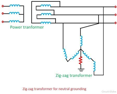
grounding banks are widely used to provide effective grounding in three phase three wire systems. A grounding bank uses either a zig-zag or wye-delta transformer which represents a high impedance path for positive sequence voltages but provides a low impedance path for zero sequence voltages. 480 To 120/240 Transformer Wiring. a volt primary transformer with a volt secondary is operated at volts, regardless of whether the source is three phase 3-wire or three phase 4-wire. .. example: A 10 kVA transformer, / volt secondary is to service an 8 kVA . Single Phase Transformer Primary and Secondary wiring. The output transformer ground wire is soldered to a speaker jack ground lug. If you use plastic speakers jacks, solder a ground wire to the jacks and bolt it down to the main ground point Your power tube cathode wires may be on the circuit board or leave the tube sockets and go right to the main ground point The wiring diagram and phasor diagram of a 180˚ connection are as shown in the figure below. Delta-Delta (Δ-Δ) Connection 180-degree connection ... If a solid grounding s provided between the star point of the primary transformer and the neutral point of an alternator, it will provide a path for the magnetizing current in the neutral wire ...
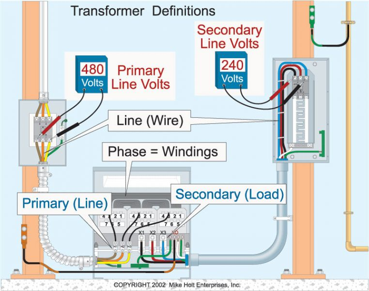
31 6013 Rev. B - Substation Standards Typical Power Circuit Breaker Wiring Diagram (Sh 3 of 3) 72. 41 1011 Rev. C - Transmission Line Standards Transmission Lines Fence Grounding Hardware In both types of grounding, the resistor is connected between the neutral of the transformer secondary and the earth ground, as shown in Figure 5. Transformer Secondary Line to Neutral Voltage Equals System Voltage Divided by 1.732 Neutral Line to Neutral Voltage System Voltage Neutral Grounding Resistor FIGURE 5 Where: I = Limit of Fault Current If we need a neutral for grounding or for supplying single-phase line to neutral loads when working with a 3-wire, ungrounded power system, a zigzag connection may be the better solution. Due to its composition, a zigzag transformer is more effective for grounding purposes because it has less internal winding impedance going to the ground than ... Five key components. Following is an overview of essential areas related to bonding and grounding single, solidly grounded, 480V - 208Y/120V, delta-to-wye, 3-phase transformers. System bonding jumper — The 2011 NEC defines the system bonding jumper as "the connection between the grounded circuit conductor and the supply-side bonding ...
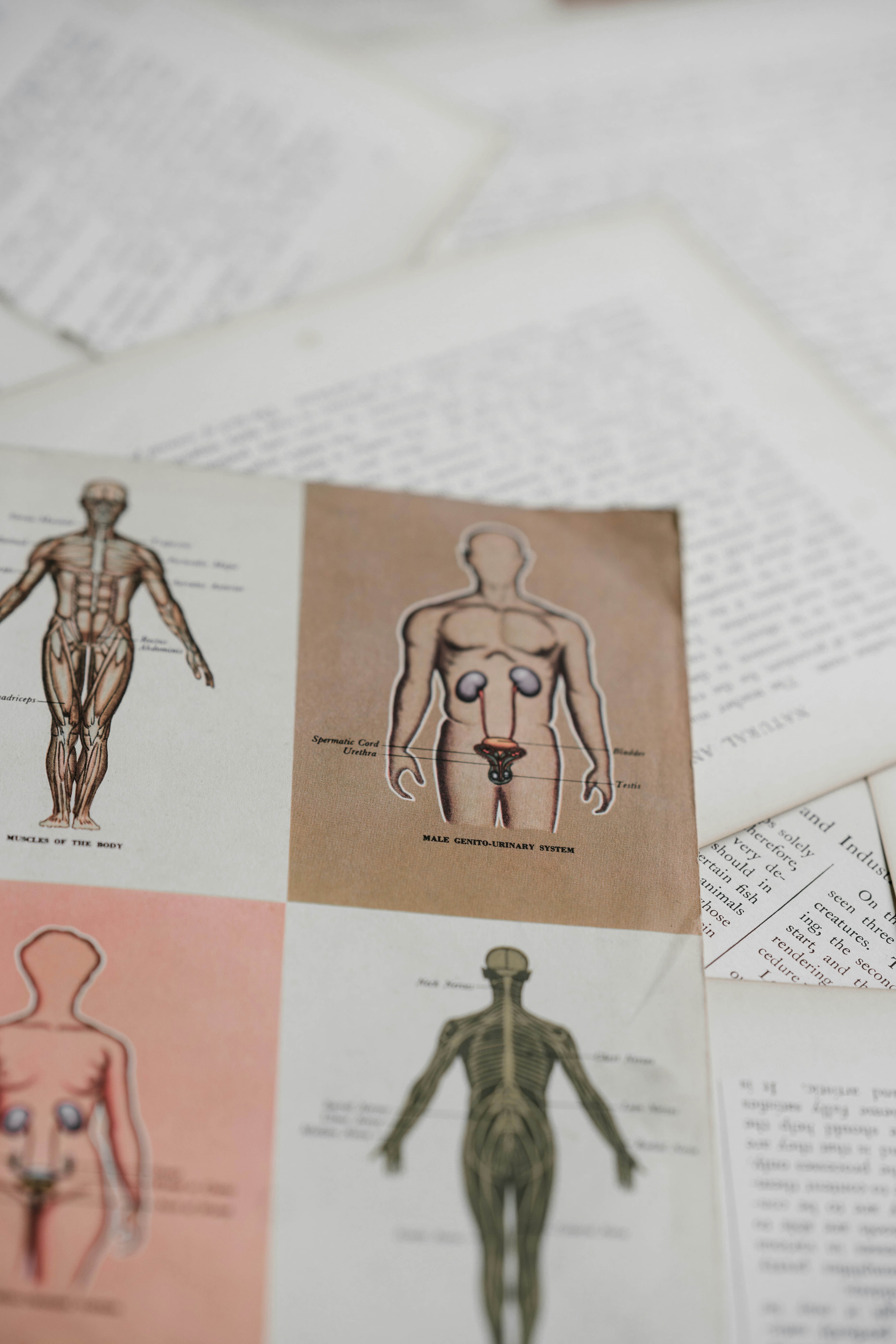
Medical diagram
This includes the high voltage wiring inside air handler unit and inside condenser/evaporator unit. Inside the air handler unit, the high voltage wiring powers the indoor fan, the heater and provide power for the transformer. Inside the condenser/evaporator unit, the high voltage wiring powers the outside fan and the compressor.

Transformer Grounding And Bonding Diagram
The Earthing or neutral grounding transformer may be two winding with a zig- zag connected primary and a star connected secondary or a single winding three phase auto-transformer with windings interconnected star or zig-zag. Earthing transformer is a three limbed core type transformer having two equally balanced windings on each core.

600 Volt Transformer Wiring Diagram - Wiring Diagram Networks
Size: 157.85 KB. Dimension: 800 x 600. DOWNLOAD. Wiring Diagram Images Detail: Name: 45 kva transformer wiring diagram - 480 to 240 transformer wiring wiring source u2022 rh tycorc co 480 Single Phase to 240V Transformer 480 Single Phase to 240V Transformer. File Type: JPG. Source: mazola.co.
30 480v To 240v Transformer Wiring Diagram - Wiring ...
CCTV Camera Installation Wiring with DVR Security System – Step by Step. To keep the system simple (as it is) we will go step by step to show how to install a CCTV (Closed Circuit Television) security camera in home, office and other sensitive places where it needed to monitor and control the security and manage proper system for better protection.
![[KD_7709] Single Phase Transformer Wiring Diagram In ...](https://static-assets.imageservice.cloud/190296/single-phase-transformer-wiring-diagram-in-addition-zig-zag.jpg)
[KD_7709] Single Phase Transformer Wiring Diagram In ...
2011 Code Language: 450.10 Grounding. Where grounded, exposed non-current carrying metal parts of transformer installations, including fences, guards, and so forth, shall be grounded and bonded under the conditions and in the manner specified for electrical equipment and other exposed metal parts in Parts V, VI, and VII of Article 250.

Wiring Schematic Of Pole Transformer - Wiring Diagram Schemas
Household Wiring. The standard U.S. household wiring design has two 120 volt "hot" wires and a neutral which is at ground potential. The two 120 volt wires are obtained by grounding the centertap of the transformer supplying the house so that when one hot wire is swinging positive with respect to ground, the other is swinging negative.
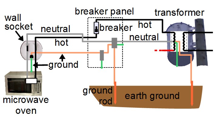
What is ground - household
Wiring a Telephone Jack After installing the Cat 3 - 3 pair phone wire I am ready to install the wall jack. You will have a wide variety of telephone jacks to choose from but the wiring for a single line phone service will be standard.
Isolated Ground Transformer Wiring Diagram - Wiring Diagram
Any wiring failure downstream from the transformer must have a way to re-enter the circuit briefly in order to trip that circuit protection device. As with any supply, it is the Neutral wire which is bonded to ground, and this will happen just after the output of the transformer. Common Wiring Configurations

An Arduino Uno board wired to a couple of sensors on a breadboard.
The grounding transformer is used to provide a path to an ungrounded system or when the system neutral is not available for some reason, for example, when a system is delta connected. It provides a low impedance path to the neutral and also limits the transient overvoltage when the ground faults occur in the system.

Closeup of skeleton pelvic model
Grounding transformer wiring diagram. C A transformer is measured individually with a minimum-loss pad as a matching circuit connected between the high-impedance winding and the instrumentation.

Grounding Transformer Wiring Diagram
The grounding electrode conductor must terminate at the same point on the separately derived system where the neutral-to-case bonding jumper is installed [250.30(A)(1)]. For a 45kVA transformer: 3/0 AWG = 4 AWG copper grounding electrode conductor. For a 112.5kVA transformer: 700kcmil = 2/0 AWG copper grounding electrode conductor.
![[RT_3425] Ground Transformer Wiring Diagram Get Free Image ...](https://static-cdn.imageservice.cloud/1163901/light-pole-base-detail-on-isolated-ground-transformer-wiring-diagram.png)
[RT_3425] Ground Transformer Wiring Diagram Get Free Image ...
the earthing transformer or grounding transformer to create a artificial neutral point for the three phase system. This is the basic theory of earting transformer, the operation and other features of an earthing transformer is described as follows. Contents 1 Construction of Earting Transformer or Grounding Transformer
What is Zig-Zag Transformer? Definition & Explanation ...
It cannot be terminated to the case of the transformer. 250.30(A)(4) Grounding Electrode. The grounding electrode conductor must terminate to a grounding electrode that is located as close as practicable to, and preferably in the same area as the nearest: (1) Effectively grounded metal member of the structure. ...

Electrical grounding | Nations Home Inspections, Inc
ACME ELECTRIC U MILWAUKEE, WI U 800.334.5214 U acmetransformer.com 125 GENERALGENERAL ELECTRICAL CONNECTION DIAGRAMSACME® TRANSFORMER™ WIRING DIAGRAMS PRIMARY: 240 Volts Delta SECONDARY: 208Y/120 Volts TAPS: 2, 5% BNFC X1 H1 X2 X3 H2 H3 X0 3 2 1 3 2 1 3 2 1 ConnectConnect Primary Primary Inter- Secondary

Transformer Grounding And Bonding Diagram
"Transformer Installations & Separately Derived System Grounding". (This Study Guide other than those established by grounding and bonding connections.". Installing transformers in accordance with the NEC is critical to ensuring a safe Size the equipment grounding (bonding) conductor for the transformer primary.

Gallery Of 3 Phase Current Transformer Wiring Diagram Sample
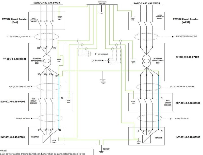
Figure 1 provides a generalized diagram of this layout. Proper grounding transformer construction Grounding transformers are normally constructed with one of two configurations: a Zig-Zag (Zn)-connected winding with or without an auxiliary winding, or a Wye (Ynd)-connected winding with a delta-connected secondary that may or may not be used to ...
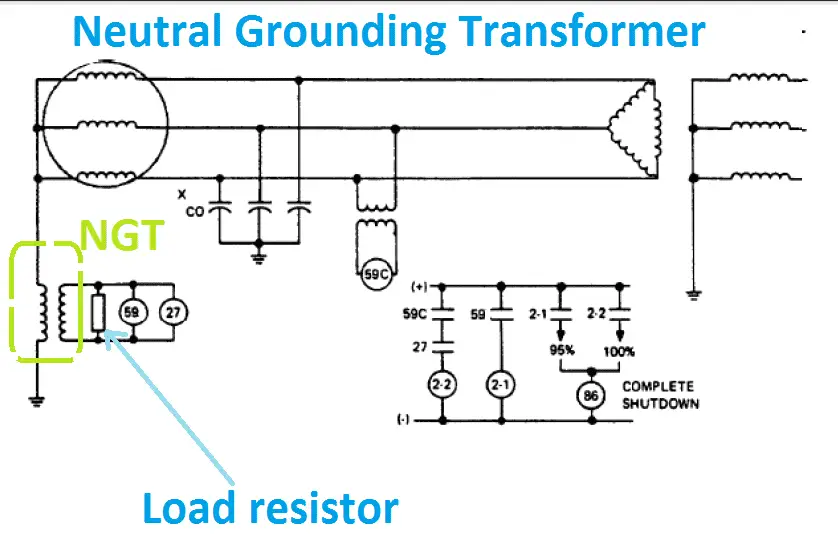
Advantage of Neutral Grounding Transformer NGT | Electrical4u
ELECTRIC POWER TRANSFORMER ENGINEERING. Ibrahim Morad. Download Download PDF. Full PDF Package Download Full PDF Package. This Paper. A short summary of this paper.

Wiring a 45KVA step-down transformer
Grounding Electrode System and Grounding Electrode Conductor Part III zNEC 250.50 (Grounding Electrode System) 250.52 Electrodes Water Pipe if 10 ft. or more of metal water pipe is in contact with the earth. Metal Frame of the Building or Structure where the following methods are used to make an earth connection: (1,2,3,4)

Closeup of skeleton pelvic model
I am installing a 45kva 3 phase delta-wye 480/208/120 transformer in a vehicle repair shop. The transformer primary will be connected to a breaker in the 480/277 building service panel. The transformer secondary will feed a 100 amp 208/120 panel for power and lighting. I want to be certa...

Image from page 321 of "The American journal of roentgenology, radium therapy and nuclear medicine" (1906)
ACME ELECTRIC † MILWAUKEE, WI † 800.334.5214 † acmepowerdist.com 157 GENERAL ELECTRICAL CONNECTION DIAGRAMSACME® TRANSFORMER™ WIRING DIAGRAMS PRIMARY: 240 Volts Delta SECONDARY: 208Y/120 Volts TAPS: 2, 5% BNFC X1 H1 X2 X3 H2 H3 X0 3 2 1 3 2 1 3 2 1 Connect Connect Primary Primary Inter- Secondary

Grounding Transformer Wiring Diagram
30 480v To 120v Transformer Wiring Diagram - Wiring ...
Soldering our wire harness for Kumpan electric scooters. 💚

Sauna - 1 Phase 240 volt - DoItYourself.com Community Forums

Transformer Grounding - Secondary - Electrician Talk ...

Get Step Up Transformer 208 to 480 Wiring Diagram Download
![[DIAGRAM] Three Phase Transformer Connection Diagrams FULL ...](https://i.redd.it/qnus093scjk21.jpg)
[DIAGRAM] Three Phase Transformer Connection Diagrams FULL ...

Mike Holt Grounding vs. Bonding - 2014 NEC Requirements ...

Step Down Transformer 480v To 120v Wiring Diagram - Wiring ...

30 High Resistance Grounding System Diagram - Wiring ...

600 Volt Transformer Wiring Diagram - Wiring Diagram Networks
Implement three-phase grounding transformer providing a ...

75 Kva Transformer Wiring Diagram - Wiring Diagram And ...

Isolation Transformer Earth Wiring | YachtForums: The ...
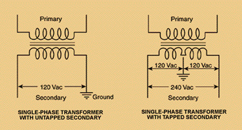
Single Phase Transformer Connections | The Electricity Forum

Grounding for Control Transformers - Technical Articles

Transformer Grounding And Bonding Diagram

Grounding for Control Transformers - Technical Articles
24 Volt Transformer Wiring Diagram | Wiring Diagram
What is the purpose of isolation transformer? What is its ...

Image from page 1073 of "Electric railway journal" (1908)
Comments
Post a Comment