40 vlan network diagram
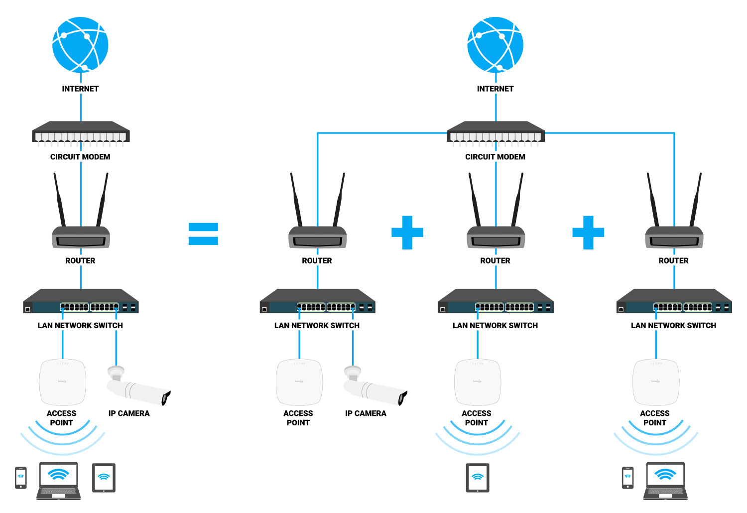
The customer network (C-network) connects to router R1 at the GigabitEthernet subinterface 0/1/0/1.1, and to router R2 at the GigabitEthernet subinterface 0/5/0/2.1. The C-network is not shown in the diagram; however, the C-network sends L2 traffic through the S-network, and the S-network switches the traffic from end to end. Basic VoIP network design. For small business VoIP installations a good basic network design can help prevent unwanted VoIP quality issues. Voice traffic starts on the local VoIP network and any steps that can be taken at the start to make a better VoIP LAN network can have a positive impact on your overall satisfaction.
Vlan Definition. Here are a number of highest rated Vlan Definition pictures on internet. We identified it from reliable source. Its submitted by paperwork in the best field. We recognize this nice of Vlan Definition graphic could possibly be the most trending subject bearing in mind we part it in google gain or facebook.

Vlan network diagram
2+ years' experience in design and implementation requirements to provide customer solutions as needed for network. This includes diagram drafting, creating a rack elevation model, requesting vendor product quotes and cost analysis. Order equipment, burn in testing and fielding rack solution where required. A logical network diagram depicts how information in the network flows. In a logical diagram, you'll generally visualize the following elements in your logical network topology: subnets (such as: IP addresses, VLAN IDs, and subnet masks,) network objects (routers and firewalls) specific routing protocols.Sep 5, 2018 + 2+ years' experience in design and implementation requirements to provide customer solutions as needed for network. This includes diagram drafting, creating a rack elevation model, requesting vendor product quotes and cost analysis. pment, burn in testing and fielding rack solution where required.
Vlan network diagram. They must provide support for LACP and other technologies used on the server side, for example, 802.1q VLAN segmentation. Access layer switches are used in stacked pairs. In MCP CPI reference architecture validation lab, the following 10 GbE switches were used as the top of the rack (ToR) for PXE, Management Public, Storage, and Tenant networks ... a. Build the network according to the logical topology by placing the required equipment in the wiring closet equipment rack. b. Cable the network devices in the closet as shown in the topology diagram. c. Connect the hosts as shown in the topology diagram. Part 2: Develop an IP Addressing Scheme VLAN Network Diagram. LAN Connection Diagram. Ethernet Frame VLAN Header. Mac VLAN. Port-Based VLAN. Gallery of Vlan Vs Lan. Green Papaya Salad Recipe Chicken Nugget Recipe Brown Rice Flour Qdoba Chicken Recipe Triple Sec Drinks Chili Chicken Recipe Chex Mix Flavors Deviled Crab Recipe Savory Sweet Potato Recipes Monte Cristo Sandwich Recipe ... According to the Lab Layout Reference Diagram, determine and apply the configuration necessary to implement inter-VLAN routing with router on a stick on NYEDGE1 for VLANs 16 - 18. Configure a default route on NYEDGE1 to 192.168.254.2.
• Develop and maintain a network diagram reflecting all equipment, WAN (including circuits), LAN including corporate equipment (switches, routers, WAP's, phones, MFD's), VLan's, and routing to cloud service providers. • Establish and maintain network administration standards for corporate equipment including network configuration and ... •By creating VLANs, you can allocate the ports to these Virtual Switches within the same physical switch. •When you assign the port on the switch to a VLAN, it will only be able to talk to other ports in the VLAN. •The ports that belong to the same network segment will be assigned the same VLAN ID. The VLAN ID is a 12-bit number (1 - 4096). Below, you can find examples of some common network configurations used for Quuppa system infrastructures. In some cases, a simple setup with the Locators and the QPE in the same subnet may be sufficient. However, if the QPE is not in the same subnet as the Locators, either the DHCP Options should be used or a VLAN connecting the QPE and the ... The diagram above shows a Cisco Catalyst 3550 selected to take the role of the network's VTP Server since it is the most powerful switch. All other Catalyst switches have been configured as VTP Clients, obtaining all VLAN information and updates from the 3550 VTP Server. ... This specially created VLAN is usually the first one in the network ...
This article introduces the Network Address Translation (NAT)concept. Learn what Network Address Translation is, how it is used and the benefits it provides to networks, companies and workplaces of any size. Our unique award-wining network diagrams are used to help illustrate the operation and concept of NAT. Command or Action Purpose; Step 1: switch# show spanning-tree vlan vlan-id detail Example: switch# show spanning-tree vlan 9 detail VLAN0009 is executing the rstp compatible Spanning Tree protocol Bridge Identifier has priority 32768, sysid 9, address 0018.bad8.27ad Configured hello time 2, max age 20, forward delay 15 Current root has priority 32777, address 0018.bad7.db15 Root port is 385 ... Ring network - do you have diagram? where switched discover its upstream switch and all vlan configured . but traffic fail to send to upstream switch. we need to look at the config or some kind of information what is configured ? Please suggest the problem area. Unifi Vlan Map. Here are a number of highest rated Unifi Vlan Map pictures on internet. We identified it from reliable source. Its submitted by executive in the best field. We take this kind of Unifi Vlan Map graphic could possibly be the most trending topic later we allocation it in google pro or facebook.
What Is a Virtual Network? A Definition - SDxCentral
Determine the prefix size for each VLAN: Servers VLAN: hosts bits >= log2 12 >= 3.584 ≈ 4 hosts bits = 4 network bits = 32 - 4 = 28 prefix size = /28 Users VLAN: hosts bits >= log2 100 >= 6.644 ≈ 7 hosts bits = 7 network bits = 32 - 7 = 25 prefix size = /25 The networks will be: 172.16.16./28 for servers VLAN and 172.16.16.128/25 for users VLAN.

VLAN Based Office Network Overview. | Download Scientific Diagram
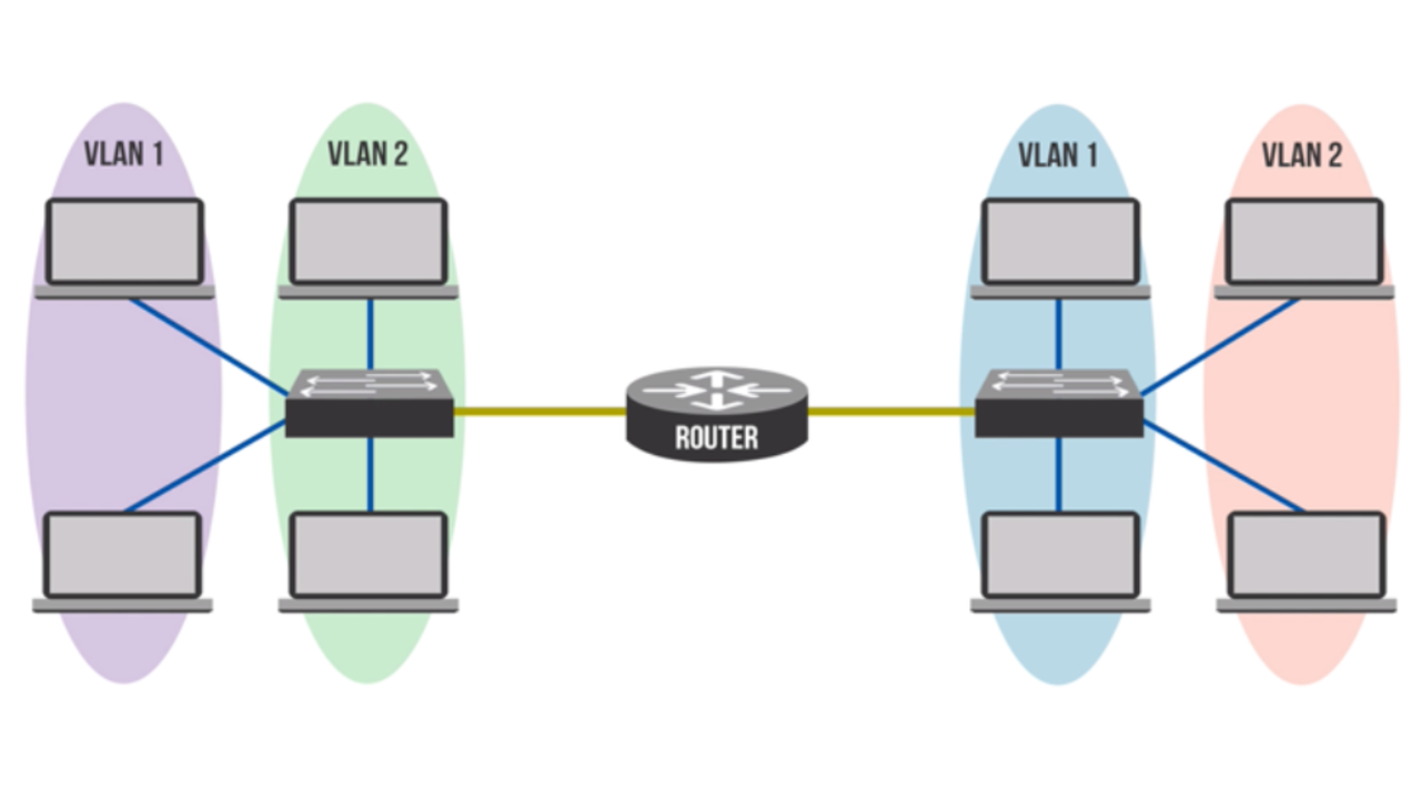
It is difficult to explain without a general diagram. You may also pass routes to the PCs through dhcp if you have multiple gateways internally. Most importantly you will need a trunk port or two on the main stack for the VLANs to be accessible for routing to the other VLANs. Reply with a general diagram and the community can assist your request.
What is a VLAN? - Beaming
VLAN Network Diagram Examples. VLAN Bridge. Collision Model. OSI Model. Ethernet Wiring Diagram. Binary Collision Diagram. Hubs Vs Switches. The Collision Theory. Collision Domain Router. Ports In Collision Domains. Gallery of Collision Domains Diagram.

Moving to VLANs from 2 LANS - Network Engineering Stack Exchange
Cisco WLC VLAN Tagging. FlexConnect VLAN Mapping. Cisco 5500 Series. Cisco WLC 8500. Cisco ACL. Reboot Cisco AP From Controller. VLAN Vs WLAN. Cisco 1602I. Cisco CAPWAP. Cisco 5508. Radius-Server. WLAN VLAN. Cisco Wireless Network Diagram. VPC And Cisco WLC. Cisco 1832. Cisco Wireless 9800. FlexConnect AP.
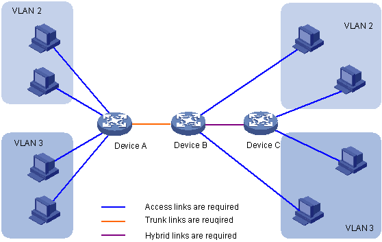
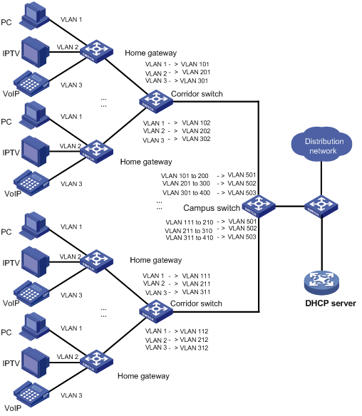
Introduction to port-based VLAN
Since I standardize the VLANs in all locations, for example using VLAN 12 for voice, then I know if the third octet is 12, it's a voice VLAN. I don't have to remember that voice in location 1 is VLAN 2, and voice in location 2 is VLAN 4 etc. I saw someone try and do that with 192.168 by just adding 100 to the third octet for their second VLAN.
Free Editable Network Diagram Examples | EdrawMax Online
Features: 8 x 10/110/1000BASE-T PoE ports, supports 802.1Q VLAN, auto voice VLAN and auto surveillance VLAN, compact desktop enclosure, lifetime warranty TODAY'S BEST DEALS View at Walmart
Designing a Fault-Tolerant Network
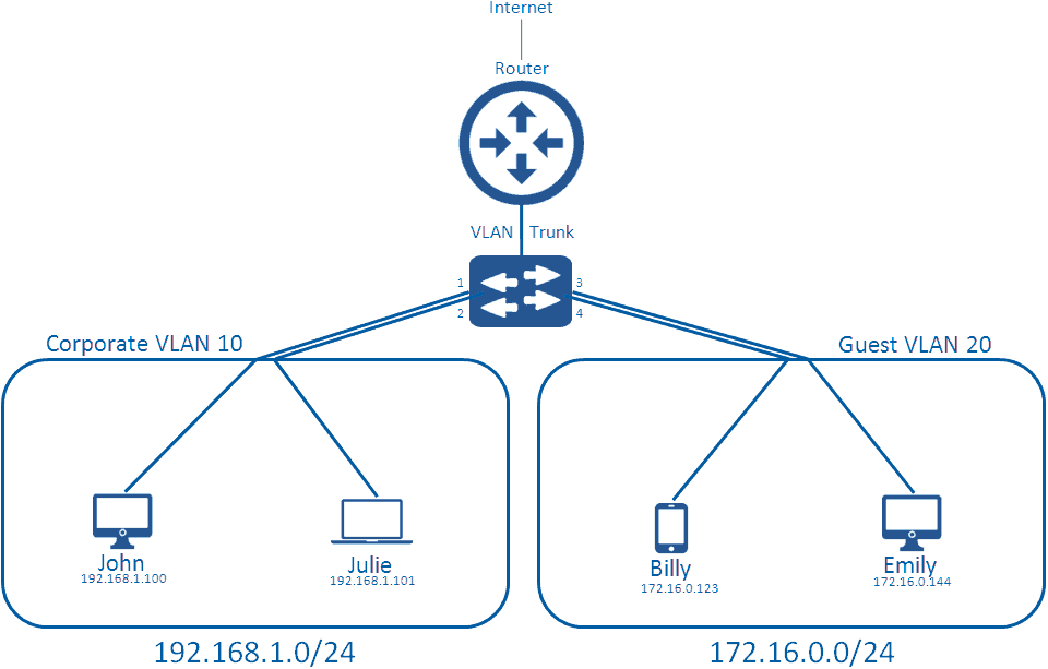
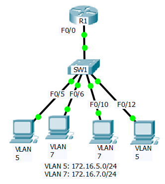
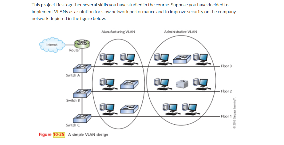
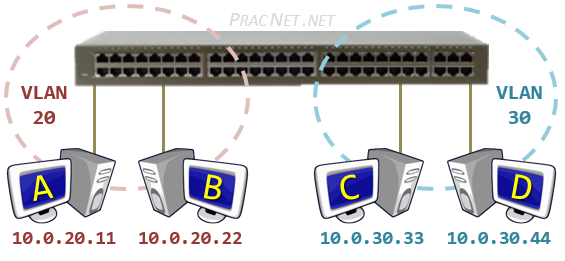
The network administrator would choose three VLAN IDs, for example, 10, 11, and 12, and would configure the switch to associate switchports with VLAN IDs. For example, switchport 2 might be associated with VLAN 10, switchport 3 might be associated with VLAN 11, and so forth.

VLAN Basic Concepts Explained with Examples
Download Plot Diagram Template 01 Plot Diagram Text Features Worksheet Plot Map. Story Plot Chart Template With Example Plot Chart Teaching Narrative Writing Teaching High School English. Plot Diagram Template Luxury Plot Diagram Template Plot Diagram Venn Diagram Worksheet Diagram.

Cisco basics of router and switch configuration | Batna24.com ...
+ 2+ years' experience in design and implementation requirements to provide customer solutions as needed for network. This includes diagram drafting, creating a rack elevation model, requesting vendor product quotes and cost analysis. pment, burn in testing and fielding rack solution where required.
Network Diagram Showing a Construction of a Network DMZ ...
A logical network diagram depicts how information in the network flows. In a logical diagram, you'll generally visualize the following elements in your logical network topology: subnets (such as: IP addresses, VLAN IDs, and subnet masks,) network objects (routers and firewalls) specific routing protocols.Sep 5, 2018

Setup VLAN subnets for home network - NetOSec
2+ years' experience in design and implementation requirements to provide customer solutions as needed for network. This includes diagram drafting, creating a rack elevation model, requesting vendor product quotes and cost analysis. Order equipment, burn in testing and fielding rack solution where required.
Solved Given the network diagram below. Enter the commands ...

VLAN segmenting existing network - Alex Scheidel - Spiceworks

VLAN Lab
New VLAN user. How to represent VLANs on network diagram? : r ...
The VLAN Concept - Introduction to VLANs
Solved: Please draw the diagram of the network solution! A
VLAN Security Concepts
VLANs: Why You Need Them and How They Work (Part 1) | EnGenius

Networking Tips Tricks: Super VLAN
Support - 12-VLAN Mapping Configuration- H3C
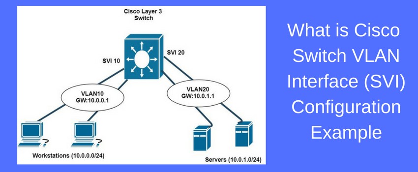
What is Cisco Switch Virtual Interface (SVI) - Configuration ...

How to Draw Clear L3 Logical Network Diagrams - Packet Pushers

What is VLAN and how it works? Advantages of VLAN - Engineer ...

Virtual LAN (VLAN) - GeeksforGeeks
Network Diagram - NetworkLessons.com Community Forum
Solved] Update the network diagram to include separate ...

Network Diagram Guide: Learn How to Draw Network Diagrams ...
Secure by Design: The Network | AT&T Cybersecurity
Corporate Network Diagram DMZ 1 Security Level - 20 192.1/24 ...
Is this a valid network diagram? - Network Engineering Stack ...
VLAN Network Diagram | Creately

Implementing Spanning Tree Protocol in VLANs | Study.com
Routing Between VLANs – Practical Networking .net

On Network Diagrams - ECG

My Visio network diagram of my plan for a small business ...
Network with multiple VLANs and a DHCP server | Creately

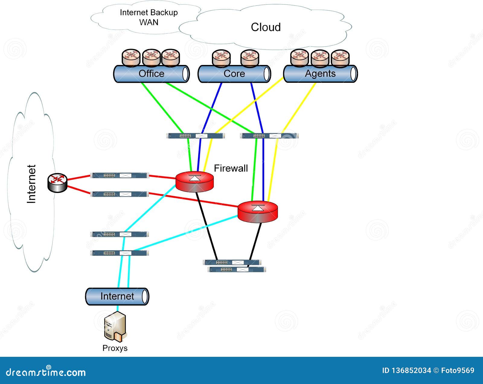
Network WLAN VLAN Diagram Illustration Stock Photo, Picture ...

What is a Logical Network Diagram? | DCIM, Network ...

What is VLAN? Types, Advantages, Example
Comments
Post a Comment