40 hydraulic solenoid valve wiring diagram
Solenoid lsarmatjc~ Mark ila Hydraulic System Parts Diagram. 39 Your WESTERN Snowplow Solenoid ISAÀMATlC~ Mark ilia Hydraulio. Unit has a serial. Western Controls and Wiring for all Western Snowplows and Salt/Sand Spreaders. HYDRAULIC HOSES On this page you will find access to all the Western plow controls and wiring that we SOLENOID CONTROL ... Solenoid valves with four-wire dual voltage coils have a wiring diagram decal, Figure 3, on the coil housing or bracket. This illustrates which wires to connect for either 120, 208 or 240 volt operation. Wiring and fusing (when used) must comply with prevailing ... CAUTION — Dangerous hydraulic pressures may develop if a hand valve is
Hydraulic solenoid selector dv50 instruction diagram summit hydraulics nachi fujikoshi corp product info equipment how to wire a valve 220v relay valves general electronics arduino forum detail hc connecting and ac power hydrawise wiring pump png 1323x760px area auto part fluid pack unit design dc with 3 diverter 13 gpm 12v plc controls molock directional control 2 spool… Read More »

Hydraulic solenoid valve wiring diagram
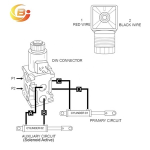
Complete workshop & service manual with electrical wiring diagrams for Caterpillar 247B, 247B2, 247B3, 257B, 257B2, 257B3 Multi Terrain Loaders. ... │ ├── Hydraulic Oil Filter.pdf │ ├── Hydraulic Tank.pdf ... │ ├── Solenoid Valve and Mounting (Parking Brake) - Remove and Install - Two Speed.pdf Solenoid-Operated On/Off Screw-In Hydraulic Valves. Start and stop flow with an electronic signal. A spring returns the valve to its default position when the signal stops. Also known as cartridge valves, these compact valves screw into your mounting block. For technical drawings and 3-D models, click on a part number. This solenoid is 12 volt dc activated. This is a safety function that keeps the hydraulics from accidentally being operated while the key is off while the mill is being worked on. With the key on the small red wire has 12 volts dc. The small black wire is ground. The two 12 volts dc when the solenoid is activated.
Hydraulic solenoid valve wiring diagram. ISARMATIC® HYDRAULIC UNIT PARTS DIAGRAM End Cap Motor Motor.combinations to direct hydraulic fluid to the snowplow lift and angle cylinders or back to the reservoir. Raise and angle functions require both the motor and solenoid cartridge valve (s) to activate, while the lower function only requires activation of a solenoid cartridge valve. Your first diagram details the solenoid coils wired as common emitter mode which means the maximum voltage across the coils will be 43 volts arduino output minus 07 The second diagram shows common collector mode and the solenoid coil will receive the full supply voltage minus 07. 1/8 Solenoid Operated Directional Valves, DSG-01 Series These are Solenoid Operated Directional Valves of high pressure, high flow and low pressure drop, the features of which can be materialized by employing a powerful wet type solenoid and the rational flow channel design. Before selecting hydraulic directional spool valves, it must be sure to choose appropriate spool valve in neutral position as per requirements of hydraulic system. For example: 1. Design pressure unloading circuit by spool function in neutral position to achieve energy savings. When H, F and G spool type in neutral position of 4way, 3postion directional spool valve, the oil fluid from pump ...
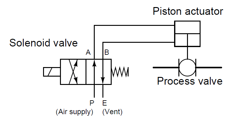
Consider solenoid valve (SOV) is Normally Close (NC) type. In normal position, the SOV is in off position or de-energized state, so the instrument air supply will be blocked as SOV is Normally closed. if SOV is energized i.e. PLC sends the signal then SOV energizes and becomes normally open (NO), so allows instrument air supply through its. Hydraulic Solenoid Valve Wiring Diagram from i.ytimg.com Print the cabling diagram off plus use highlighters to be able to trace the circuit. When you make use of your finger or stick to the circuit together with your eyes, it is easy to mistrace the circuit. A single trick that I actually use is to print the same wiring diagram off twice. Here are a number of highest rated Solenoid Valve Wiring Diagram pictures on internet. We identified it from honorable source. Its submitted by organization in the best field. We admit this kind of Solenoid Valve Wiring Diagram graphic could possibly be the most trending topic later than we part it in google plus or facebook. Hydraulic Solenoid Selector Dv50 Instruction Diagram Summit Hydraulics How To Wire A Din Connector How To Wire 3 Wire Motorized Ball Valve How To Wiring Dc Solenoid Valve With 3 Wire General Electronics Arduino Forum Solenoids U70 G70 Series Mc Hi Tech Controls Camozzi 2 W600 Wiring Solenoid Valves Youtube How To Wire A Din […]
Motor valve operator c. Solenoid valve operator d. Piston (hydraulic) valve operator e. Hand (manual) valve operator f. Reach rod valve operator EO 1.3 IDENTIFY the symbols used on engineering P&IDs for educators and ejectors. EO 1.4 IDENTIFY the symbols used on engineering P&IDs for the following lines: a. Process e. Instrument signal ... Wiring Diagram Feom Gmc To Atlas Copco Pressor Tsb Wiring Diagrams 1996 1998 Egr Valve Lift Sensor Circuit Diagram 1 6l Civic Hydraulic Solenoid Wiring Diagram Automotive Wiring Schematic. Egr Valve Wiring Diagram. Here are some Details of hydraulic pump electric diagram,12vdc hydraulic power unit and 24vdc Hydraulic Power Pack hydraulic circuit diagram and electrical diagram. And more, A wireless remote connect wire drawing also show below for single acting Hydraulic Power Pack .This Wireless Remote can be with a quick connector ,can be changed with our standard 2 … Solenoid control valves that change valve position Open/Close etc by direct movment from a solenoid are called Direct Acting. Solenoid control valves that change position Open/Close etc by opening small pilot circuits allowing pressurised air, fluid or gas to move the valve are called pilot operated or servo pressure assisted valves.
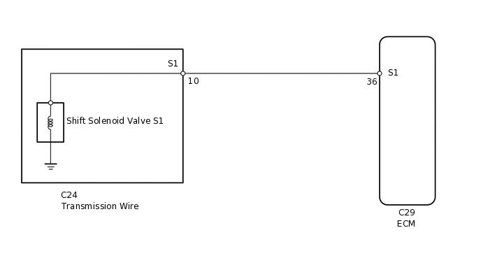
AUTOMATIC TRANSMISSION SYSTEM, Diagnostic DTC:P0973 and P0974
The one where I wire up the solenoid valve so that I can use it with a prop. Since the kneeling monk prop is largely completed I prepare the solenoid valve f...

EMERSON – ASCO Solenoid Valve Coil 400 325 142, Series 238 24 V dc
The gamma/ XL is a smart, connectible solenoid-driven metering pump that is setting new standards in terms of productivity, reliability and cost-effectiveness.
Vickers DG4V Solenoid Directional Valve from China ...
Title: D03, D05 and D08 Solenoid Valves.pdf Author: marcus.kennedy Created Date: 12/2/2010 9:42:13 AM Keywords ()
What is a 4-way Solenoid Valve? - Instrumentation Tools
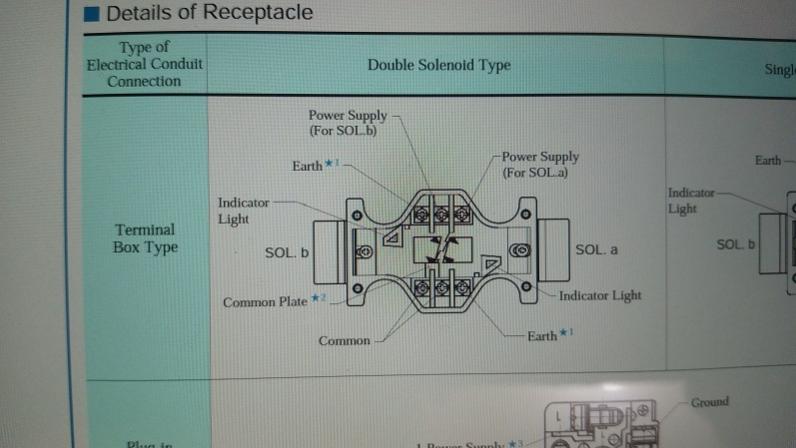
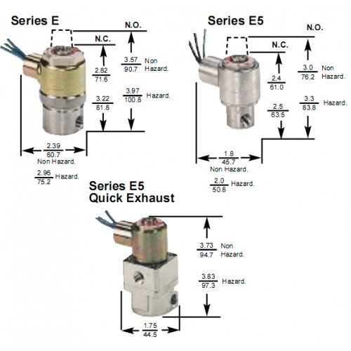
•Hydraulic shockless AC valves are always supplied with rectifier. ... Electrical Box Wiring Double Solenoid Single Solenoid. AC Solenoid AC Solenoid DC Solenoid Units: Inches SOL b SOL b SOL b SOL a SOL a 1.81 Push pin for manual operation (2) 1/2" NPT 1.00 1.87 2.80 3.48 Indicator Light SOL b
hydraulic solenoid valve 24 volt, hydraulic solenoid valve 24 ...
The braking force of the rear wheels is regulated by a single solenoid valve. This type hydraulic units are used in parallel brake circuits. 5.4. Two-channel ABS This type of hydraulic unit is used on heavy vehicles or on vehicles such as trucks. Only the rear two wheels are controlled. 5.5. One-channel One-sensor ABS This type of anti-lock system is usually found in SUVs in VANs …
Practical Machinist - Largest Manufacturing Technology Forum ...
Three hydraulic solenoid valves are used in the HT300 power unit. They all use the same coil - so coils can be swapped to aid in troubleshooting. The solenoid coils act as electromagnets, and pull on an armature and spool or poppet inside the valve. A valve may malfunction due to faulty

Solenoid Valve Installation | Tameson.com
The solenoid locks out the coupler, allowing you to back up the trailer without the brakes actuating. If you are using a 5-pole connector, the blue wire from the connector would tap into the reverse light circuit. I have provided a diagram that should help illustrate this for you.

Types of Solenoids
•Electrical power should be maintained on detented valves (spool code 3A). Detent only maintains start-up position of the valve. 31341 Friendship Drive, Magnolia, TX 77355 • Tel.: 281-259-7768 Fax: 281-259-7249 • www.hyvair.com D05 Series 35- Solenoid Operated Directional Valves Electrical Information Solenoid Coil Specifications

Hydraulic Solenoid Valve - How They Work | Tameson.com
Hydraulic solenoid Valve Wiring Diagram. Collection of hydraulic solenoid valve wiring diagram. A wiring diagram is a simplified standard pictorial representation of an electric circuit. It reveals the components of the circuit as streamlined shapes, as well as the power and also signal links in between the gadgets. A wiring diagram normally provides details about…
Completing the Hydraulic Drawing | AutoCAD Electrical 2019 ...
P1198 Malfunction of the fuel flow control solenoid valve It is noted that the flow rate is critically low, which will affect the operation of the engine. P1490 At Citroen 2001, 2006, 2008, 2012 and other years of production, this code indicates that the particulate filter was not regenerated. This process began, but did not end. The problem is the malfunction of the filter device due to its ...

Hydraulic Solenoid Selector DV50 Instruction Diagram - Summit ...
Control the direction of flow or stop flow altogether with an electronic signal. These valves are also known as cartridge valves, and they screw into your mounting block.. Place three-way valves between the pressure source and a single-acting cylinder. Place four-way valves between the pressure source and a double-acting cylinder.. In NFPA diagrams, P represents the pressure source, T ...

China Anlite Hydraulic Solenoid Valve Coil with High Quality ...
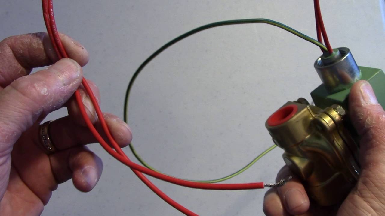
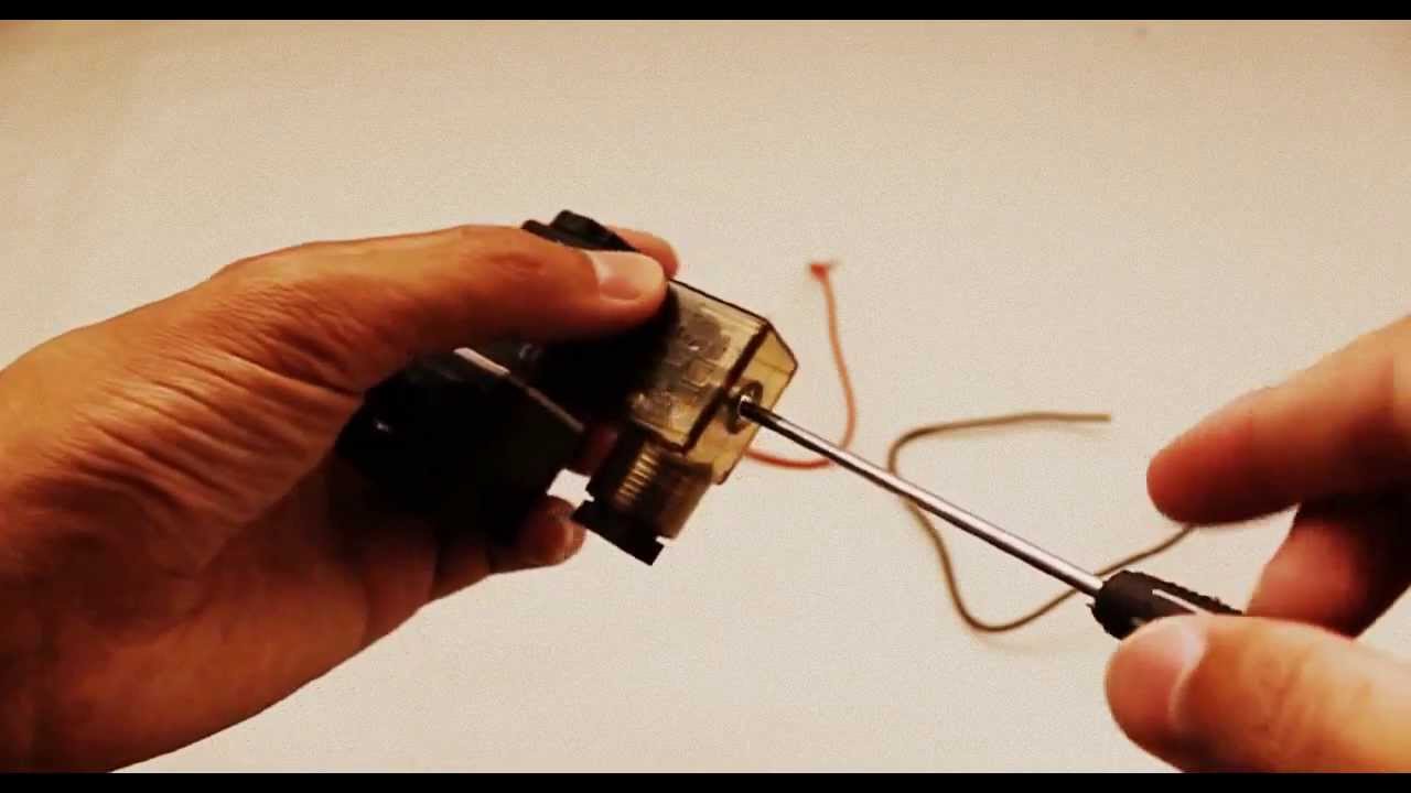
Procedure on how to wire the electrical components in a solonoid valve, brought to you by http://stcvalve.us/CAUTION: Do not energize the coil before it is a...

Relay-based Electro-hydraulic Systems – FLUIDSYS TRAINING CENTRE
Motor runs, but unit will not build hydraulic pressure Solenoid valve manual override is open Some of our units (Option 2) are equipped with a two position valve with a mechanical manual override (Item A). With stem of valve pointing up, push down and turn clockwise until stem won't turn, and let go. Valve is now closed.

How to Electrically Wire Up a 12 Volt DC Hydraulic Pump Power Pack Twin Solenoid Coils & Thermistor
We are a global market leader in the production of electric, hydraulic and pneumatic valve actuators and gearboxes to manage the flow of liquids, gases and powders. Our products can be found across numerous sectors including oil and gas, water and power, and chemical, process and industrial. Our mission is to be the industry leader in flow control and instrumentation …

Solenoid Valve: What Is It? How It Works, Materials & Uses
How to select a pneumatic solenoid valve for a single acting pneumatic cylinder? Summary. A single acting pneumatic cylinder is a linear actuator and realizes a working stroke by filling the cylinder with compressed air. The return stroke is usually accomplished by a spring. The cylinder has one connection port that is used either to fill or vent the cylinder. To control the cylinder, a …

Hydraulic Solenoid Valve - How They Work | Tameson.com
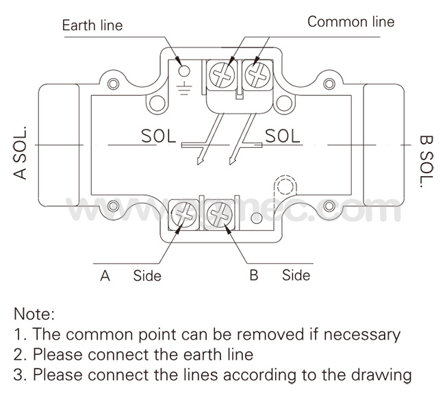
The wiring diagram of the solenoid valve is as below. Although the wiring of solenoid valve is simple, but poeple still encouter problems when wiring the solenoid valve to other devices. Here are some problems for your reference. 1. Is it that the solenoid valve on the pneumatic stop valve can be two-wired, three-wired or four-wired?
W600 Wiring: Solenoid Valves
The wiring diagrams represents only examples. Because of the varied usability different circuits are possible. Parker Hannifin GmbH Hydraulic Controls Division SEITE1_UK 1. Parker Hannifin GmbH Hydraulic Controls Division SEITE2_UK ... flow valve solenoid B 32bd 26bd 18bd 26z 16d 12z 2d 18z 4d 20d 20z 14d 14b 12b 10z 22bdz 28bdz 32z 8z 6d 6z 4z ...

Troubleshooting for Recurrent Solenoid Burn Out - Womack ...
Rotork IQ3 Range Intelligent Electric Valve Actuators - Product Literature

How to Wire Hydraulic Power Pack,Power Unit Diagram Design
This solenoid is 12 volt dc activated. This is a safety function that keeps the hydraulics from accidentally being operated while the key is off while the mill is being worked on. With the key on the small red wire has 12 volts dc. The small black wire is ground. The two 12 volts dc when the solenoid is activated.

Relief valve Ball valve Solenoid valve Vacuum breaker, hot ...
Solenoid-Operated On/Off Screw-In Hydraulic Valves. Start and stop flow with an electronic signal. A spring returns the valve to its default position when the signal stops. Also known as cartridge valves, these compact valves screw into your mounting block. For technical drawings and 3-D models, click on a part number.

Pneumatics Hydraulics Solenoid valve Pneumatic circuit ...
Complete workshop & service manual with electrical wiring diagrams for Caterpillar 247B, 247B2, 247B3, 257B, 257B2, 257B3 Multi Terrain Loaders. ... │ ├── Hydraulic Oil Filter.pdf │ ├── Hydraulic Tank.pdf ... │ ├── Solenoid Valve and Mounting (Parking Brake) - Remove and Install - Two Speed.pdf

How to Wire Hydraulic Power Pack,Power Unit Diagram Design
How to Connect Various Wires to the DC Hydraulic Power Pack ...
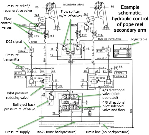
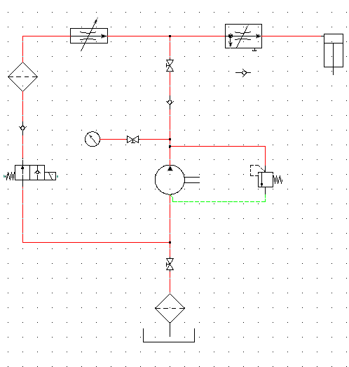
Reading fluids circuit diagrams - hydraulic circuit examples
Solenoid Valves | Solenoid Solutions
NACHI-FUJIKOSHI CORP. / Product Info. / Hydraulic Equipment
Versa solenoid valve 3-WAY DIRECT SOLENOID VALVES

Engineering Projects/Igloo/Howard Community College/Fall2012 ...
Solenoid Valve Electrical Connection Procedure

Solenoid Valves | Discrete Control System Elements ...

4V210-08 Pneumatic Air Valve 24 Volt DC 110V AC220V 4V210 08 ...
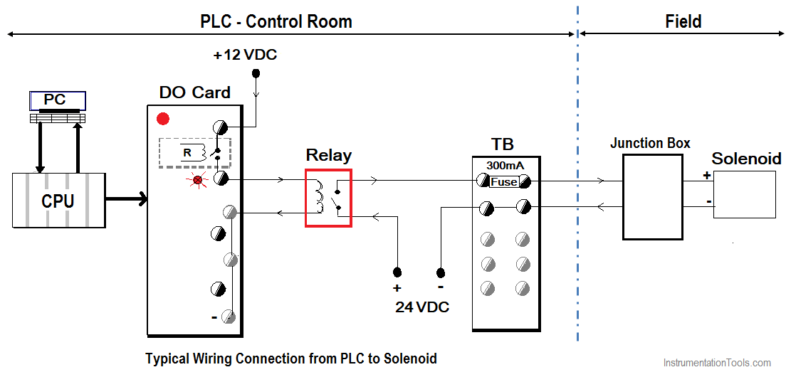
How to Connect a Solenoid Valve with PLC? - InstrumentationTools

Directional Control Valves | Parker NA

Mounting plate solenoid valve - Excavators Volvo EC340 ...

Hydraulics, Pneumatics, Pumps & Plumbing Business ...
PLC Controls a Solenoid Valve with a Relay

How to Read a Spool Valve Schematic Drawing - RealPars

22 Best Hydraulic system ideas | hydraulic, hydraulic systems ...
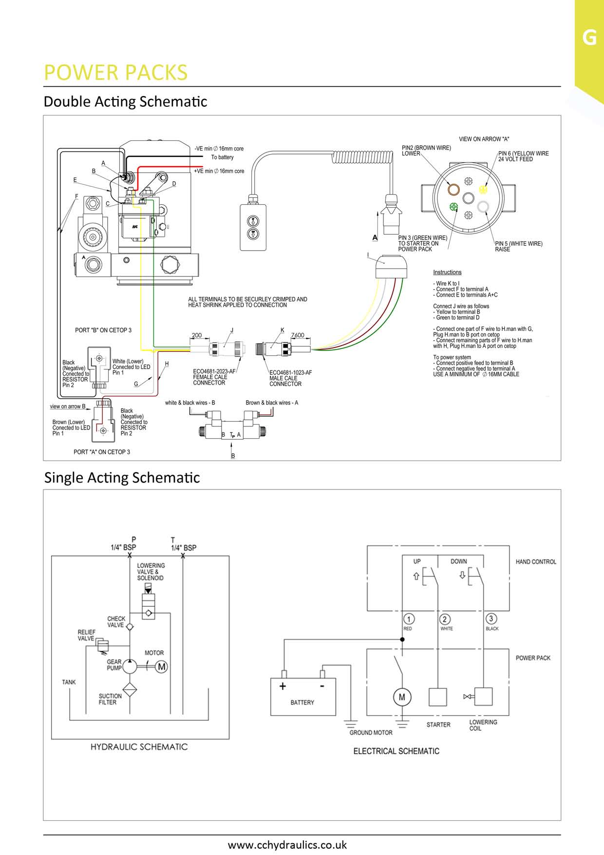
DA & SA Wiring Diagrams - C&C Hydraulics Ltd

Practical Machinist - Largest Manufacturing Technology Forum ...
Comments
Post a Comment