40 compustar wiring diagram
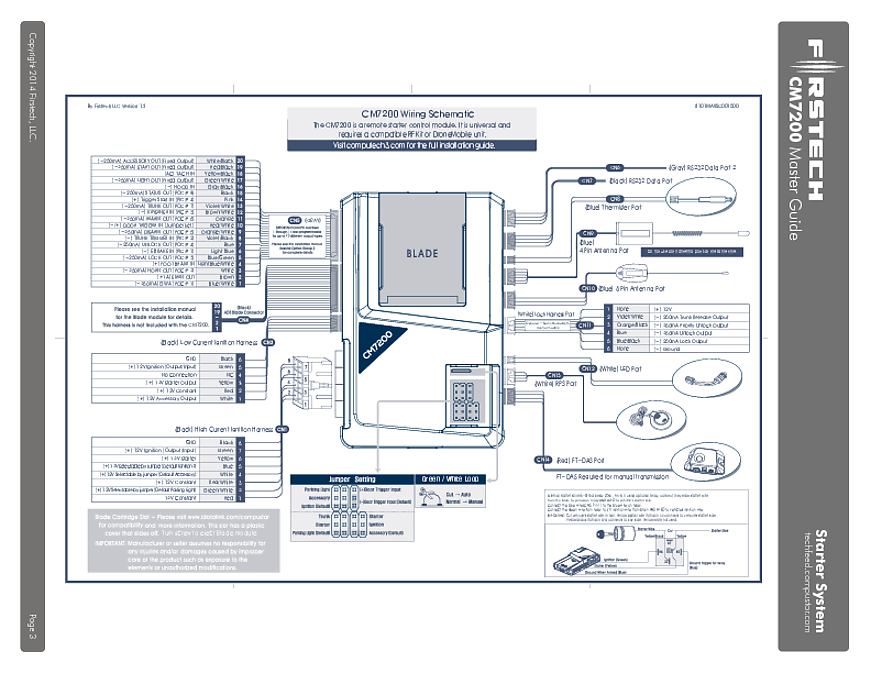
Compustar remote starter and security systems come in a wide variety, pairing with almost all vehicles on the road. There's a system designed for your car, find it today! Build a System Products About Support Blog Find a Dealer. Systems. Remote Start + Security. Remote Start. Security. Categories. All-in-One Bundles; u.s. patent no. 8,856,780 4 5 3 1 2 6 m6 functions defined by firmware automatic transmission cut loop box contents ft-das - 4 pin red ble - 4 pin yellow rf port - 4 pin blue
User Manuals. The following table charts all of Compustar’s current remote transmitters, along with their corresponding user manuals; available in English, French, and Spanish. If you cannot find your remote here, try looking through our lineup of Discontinued Remote Transmitters. Remotes Accessories. Remotes. Model # / Remote #. Quick Start PDF.

Compustar wiring diagram
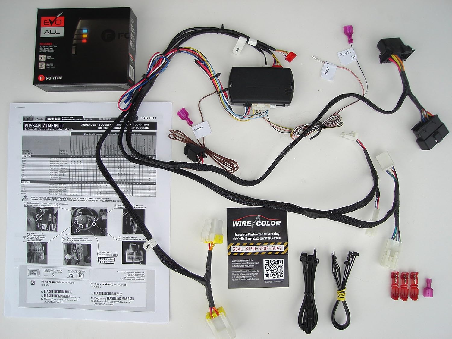
• Wiring diagram sheet • High Current ignition harness with one external relay (C M900AS only) • Additional I/O Wiring harnesses • Hood pin • Mountable bright blue LED (CM900AS only) • FT-SHOCK dual stage impact sensor (CM900AS only) • RF Kits with remote(s ), Antenna, and Antenna Cable Compustar CS920S Install Guide. 3 yrs ago; 1756; Product Wiring Diagrams & Schematics; document_20175110_095112_cm-900sfullinstallguidev1_0. Compustar CS920S Install Guide . ... Vehicle Wiring Diagrams & Schematics; Relays/Switches/Diode Wiring Diagrams; General Tech Tips; Tags. View all tags - Wiring diagram sheet - Main ignition wiring harness with two external relays - Wiring harnesses - Hood pin RF Kits with remote(s), Antenna, and Antenna Cable are not included with the FT-6200S CONT. The following sensors are available but not included with every system: - Firstech secure valet switch (FT-VALET GREY)
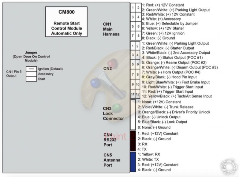
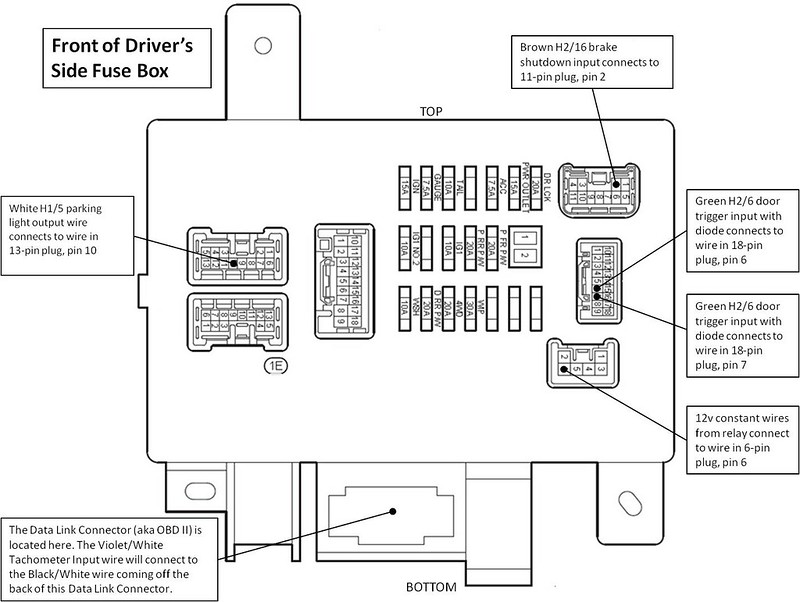
Compustar wiring diagram. Compustar CS7900 AS Installation Manual. Hello I have a Compustar CS7900 AS that I had installed in my previous car. The car was hit and totaled. I pulled out the system before sending it to the junkyard and would like to transfer it to my new car but I lost the manual. Does anyone have this manual with the wiring diagram by chance? - Wiring diagram sheet - Main ignition wiring harness with two external relays - Wiring harnesses - Hood pin RF Kits with remote(s), Antenna, and Antenna Cable are not included with the FT-6200S CONT. For more information on how to program and wire the Blade, please visit compustar.idatalink.com for the specific wiring diagram for that vehicle. Connector 3 ( ... and connect the wire accordingly: Yellow/Black will connect to the key side and the yellow will connect to the motor side (starter side). Pin #7: Green- This wire is used to power the (+) ignition. This wire is also an input for the CompuStar used to monitor the status of the vehicle and for programming.
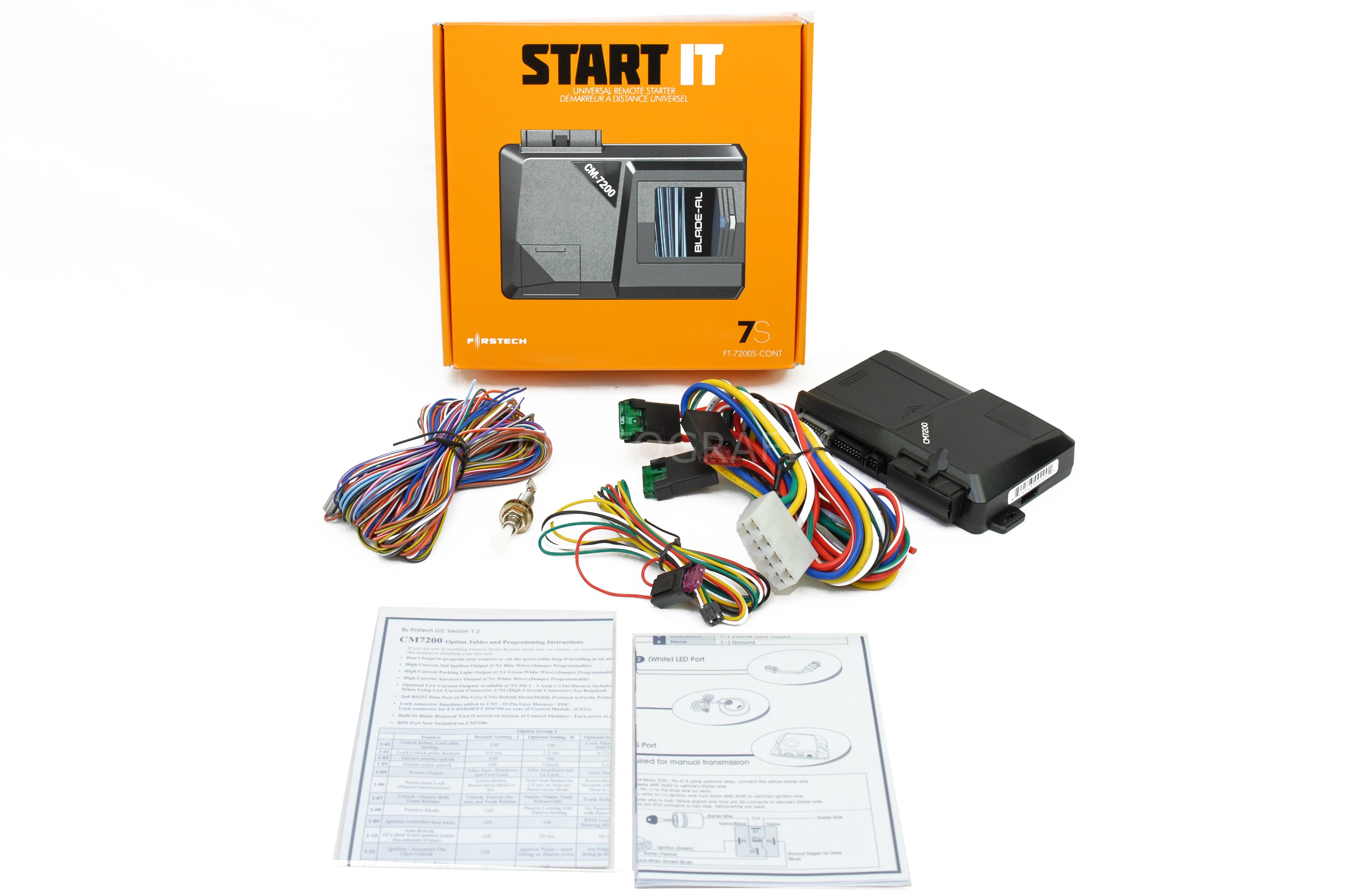
Compustar CM7000 & FT-ELock Relay. 1998 Toyota Camry Compustar CM7000 I just wanted to clarify some things with my next install with some of you guys or those that are familiar with Compustar and or Firstech products. Out of the box my relay is setup as the following 87- Yellow/white (I removed pin/and wire, not being used) 87a- Yellow/Black 86 ... Wiring diagram sheet. • High Current ignition harness with one external relay. • Low current ignition harness. • Wiring harnesses. • Hood pin. Wiring Diagram 3 Introduction 4 Kit Contents 4 Installation Basics 4 Remote Programming Routine 6 Valet Mode 8 Placement and Use of Components 9 Tach sensing & learning 13 Manual Transmission vehicles 14 System reset 16 ... • Wiring diagram sheet • High Current ignition harness with one external relay • Low current ignition harness • Wiring harnesses • Hood pin RF Kits with remote(s), Antenna, and Antenna Cable are not included with the FT-7200S CONT. The following sensors are available but not included with every system:
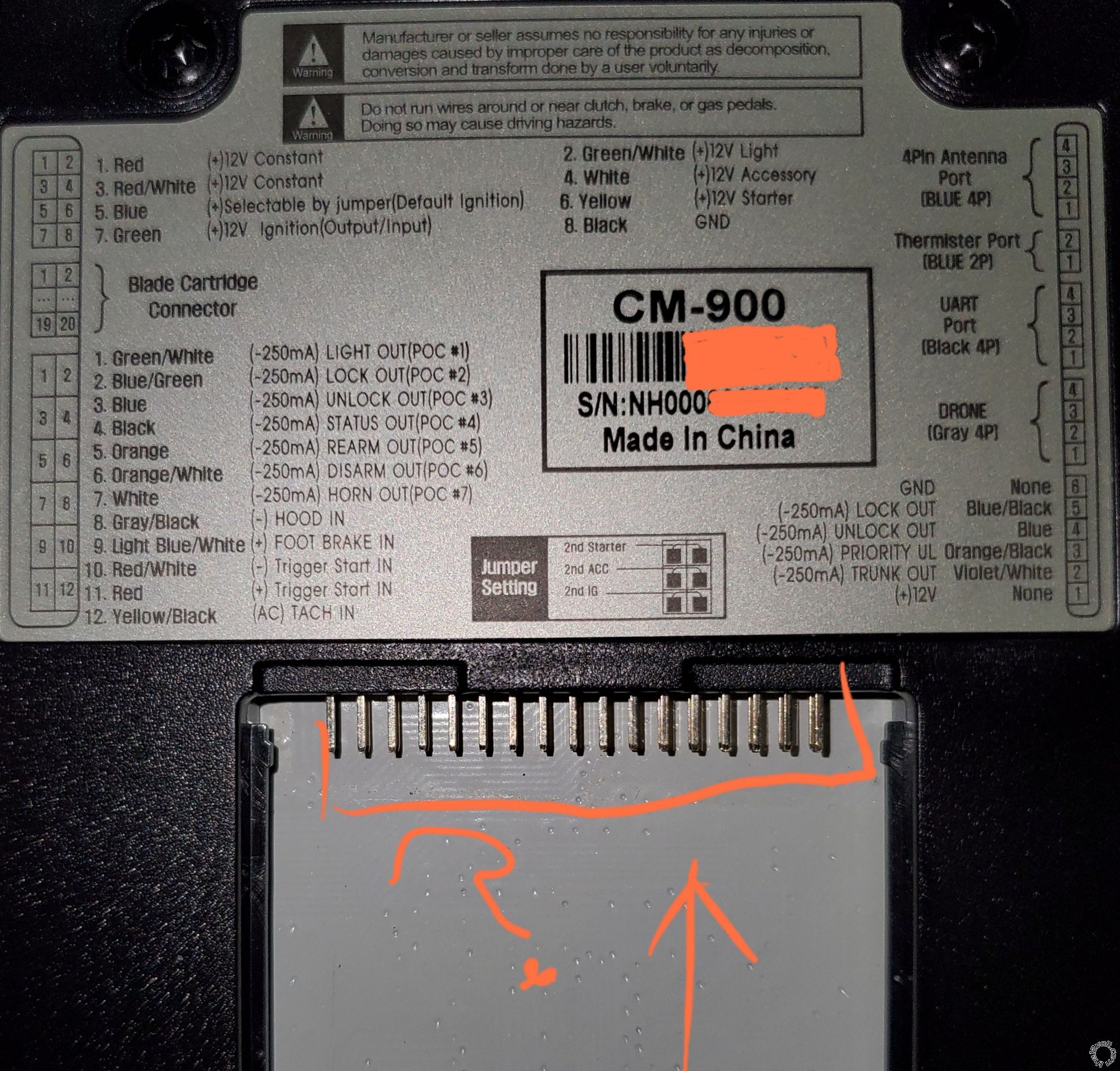
HI guys. I have a Compustar DC3 alarm module with the DAS 2 shock. On the DC3 moduel there is a daily that you adjust from 0-10 and also on the DAS2 you can access the program functions on what sensor to adjust. Compustar Remote Start Wiring Diagram. Wiring Diagram. A. Notes for Wire Connection. INSTALLATION GUIDE. How To Install A Remote Start Alarm Completely From Start To Finish on Any Honda 2001 2017 1 HR Vid. By Firstech, Inc. Website: schematron.org TABLE OF CONTENTS. Review wiring diagrams & programming sections. All control modules come with 9 programmable outputs that can be configured 19 different ways. It is important to familiarize yourself with the POCs as it will save time in most applications. Internet updatable processors . Visit "Dealer Support" at www.compustar.com Product Wiring Diagrams & Schematics cm-900sfullinstallguidev1- cm-900soptiontablev1- cm900s_as_master_guide_v1_11 Document_20194315_094305_CM900S-AS_Full_Install_v1.11-2019 Compustar CM900S Install Guide | CM900
Excalibur Remote Start Wiring Diagram - Wiring Forums
Compustar Remote Start Wiring Diagram – wiring diagram is a simplified standard pictorial representation of an electrical circuit. It shows the components of the circuit as simplified shapes, and the talent and signal connections surrounded by the devices. A wiring diagram usually gives instruction virtually the relative position and ...
Compustar CS800-s remote starter installation problem ...
Compustar's 2021 Holiday Gift Guide November 15, 2021 Can You Remote Start a Manual-Transmission / Stick-Shift Vehicle? September 30, 2021. Don't See Your Vehicle? If your vehicle is not listed above, your vehicle may not yet be compatible with Compustar. We recommend contacting your nearby Authorized Dealer to confirm what features and ...

32 Compustar Cs800 S Wiring Diagram - Wiring Diagram Database
Compustar Cm6200 Wiring Diagram. Installation manual cm6200 starter 2017 camry with and blade al wiring schematic manualzz master guide 2003 chevrolet 2500 gas. Installation Manual Cm6200 Starter System Model Rf 2w900fm 5pt Version Pdf Free.

Compustar 7900as Wiring Diagram - puertoricoinform
STEP 2: Test wire and make connection. The stator wire is found at the vehicle’s alternator. Change your meter to DC before testing for this wire. A. At rest, with the ignition off, the stator wire should test 0V DC. B. Turn the ignition to the run position. The stator wire should now test between 1 – 6V DC.

white pasta on white paper
STEP 2: Test wire and make connection. The stator wire is found at the vehicles' alternator. Change your meter to DC before testing for this wire. A. At rest, with the ignition off, the stator wire should test 0V DC. B. Turn the ignition to the run position. The stator wire should now test between 1 - 6V DC. C. Start the vehicle with the ...

white animal skull on white surface
SEATTLE– Compustar, maker of car remote start and security systems, will release Computech 3.0, an extensive database of vehicle specific wiring schemes and installation tips for authorized Compustar installers. Computech 3.0 will go live on Tuesday, April 2 at 9am PST, featuring wiring schematics data on over 18,000 vehicles. Additional resources include installation tips for […]

safeguard alarm wiring diagram, - Style Guru: Fashion ...
- Wiring diagram sheet - Main ignition wiring harness with two external relays - Wiring harnesses - Hood pin - Mountable bright blue LED - Firstech dual stage shock sensor RF Kits with remote(s), Antenna, and Antenna Cable are not included with the FT-6000AS CONT.
Kenworth Battery Wiring Diagram : Installing Batteries ...
Compustar Cs6900-as Wiring Diagram. Download Compustar user manuals for your Compustar remote car starter or security alarm system. Files are available in PDF format. See pictures, installation guides, user manuals and full product information for CompuStar Alarm Systems with Remote Starter CSAS (Manual w/ Push.
Compustar Remote Start Wiring Diagram
Product Wiring Diagrams & Schematics Reported - view Compustar CM2305: The main Car Battery on my car was disconnected and the drivers door was left open for a long period of time.

gray rope on brown wooden table
Nissan Sentra (PTS) 2016. 12/2/2021 11:23:48 AM. Subaru Impreza 2004. 11/29/2021 1:38:14 PM. Toyota Land Cruiser 1993. 11/26/2021 3:36:48 PM. ×. Submit a Tip. Send us vehicle information, images, or anything that can help us provide more data to your fellow installers.

Xl350 Wiring Diagram - Wiring Diagrams / Architectural ...
Compustar CM6300 Install Guide. 4 yrs ago; 299; Product Wiring Diagrams & Schematics; cm6300_full_install_7-11_en-1. Compustar. Install Guide. Like Follow. Reply Oldest first. ... Relays/Switches/Diode Wiring Diagrams; General Tech Tips; Tags. View all tags Visit our Website ...
![[DIAGRAM] Compustar Wiring Diagram](https://i.pinimg.com/736x/7b/62/fe/7b62fecfdeb3d6751d0afe299b139282.jpg)
[DIAGRAM] Compustar Wiring Diagram
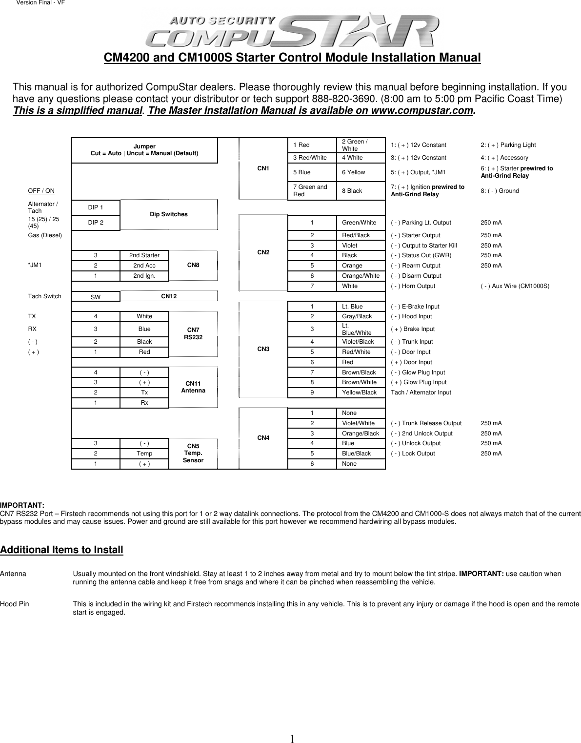
Wire Connection for Automatic Transmission vs. Manual Transmission. For manual transmission vehicles, three additional connections are required - 1) Red/White or Red wire of CN3 to the door switch, 2) Light Blue wire of CN3 to the emergency brake and 3) Red/Black wire of CN2 to over-ride the clutch switch momentarily during remotestart. 7.

Compustar Cs6900-as Wiring Diagram
- Wiring diagram sheet - Main ignition wiring harness with two external relays - Wiring harnesses - Hood pin RF Kits with remote(s), Antenna, and Antenna Cable are not included with the FT-6200S CONT. The following sensors are available but not included with every system: - Firstech secure valet switch (FT-VALET GREY)
compustar wiring diagram - Wiring Diagram
Compustar CS920S Install Guide. 3 yrs ago; 1756; Product Wiring Diagrams & Schematics; document_20175110_095112_cm-900sfullinstallguidev1_0. Compustar CS920S Install Guide . ... Vehicle Wiring Diagrams & Schematics; Relays/Switches/Diode Wiring Diagrams; General Tech Tips; Tags. View all tags
Compustar Cs6900-as Wiring Diagram
• Wiring diagram sheet • High Current ignition harness with one external relay (C M900AS only) • Additional I/O Wiring harnesses • Hood pin • Mountable bright blue LED (CM900AS only) • FT-SHOCK dual stage impact sensor (CM900AS only) • RF Kits with remote(s ), Antenna, and Antenna Cable

silver and black round coins

Compustar Remote Start Wiring Diagram Excalibur Inside ...
Avital 3100 Wiring Diagram
Compustar Cs6900-as Wiring Diagram
Compustar Remote Start Wiring Diagram Collection

Electric Scooter Throttle Diagram / Electric Scooter ...

confirm 2007 subaru outback and cm7200?

Compustar Cs800-S Wiring Diagram For Your Needs
Compustar Remote Start Wiring Diagram - Wiring Diagram

Directed Remote Start Wiring Diagram - Wiring Diagram

Compustar Cs6900-as Wiring Diagram

Compustar Cs800 S Wiring Diagram - General Wiring Diagram

Rsx Alarm Wiring Diagram - Electrical Diagram Images Guide

green and yellow map
person holding red metal frame

1996 Lexus Ls400 Fuse Box Diagram : Diagram Database Free ...

32 Compustar Cs800 S Wiring Diagram - Wiring Diagram Database

Excalibur Remote Start Wiring Diagram - Wiring Forums
compustar cm4200 wiring diagram - Wiring Diagram
Valet Remote Start Wiring Diagram - Complete Wiring Schemas

12 New Autostart Remote Starter Wiring Diagram Images ...

96 Camry Remote Start Wiring Diagram - Wiring Diagram Networks

Kenworth Battery Wiring Diagram : Installing Batteries ...

navigation map
45 Starter Kill Relay Wiring Diagram - Wiring Diagram ...
Comments
Post a Comment