40 3 pin flasher relay wiring diagram
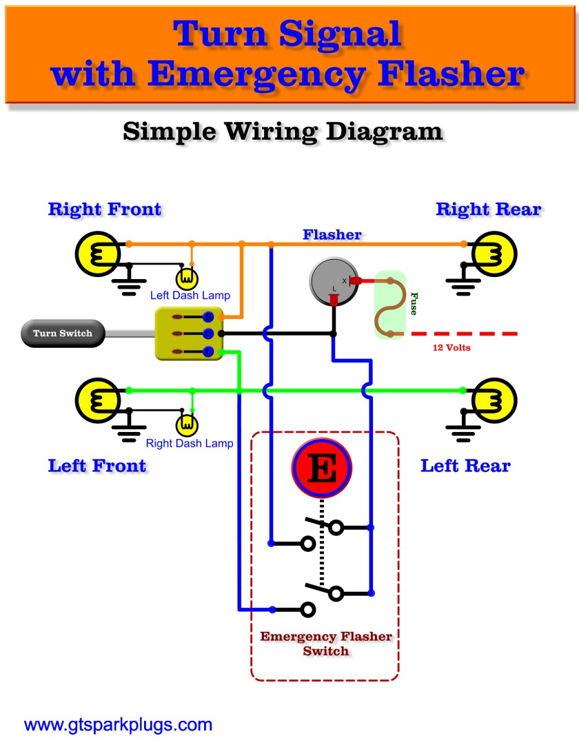
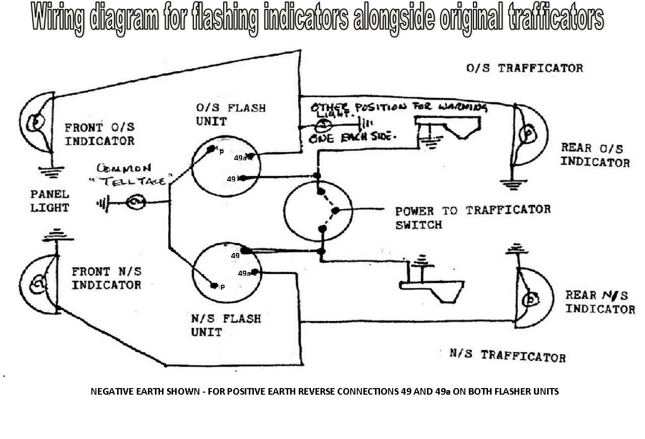
Blinker Relay 3 Pin Flasher Relay Wiring Diagram Manual Source: lambertsbikes.com. READ 1996 Honda Cbr 600 F3 Wiring Diagram For Your Needs. Read electrical wiring diagrams from bad to positive and redraw the routine being a straight collection. All circuits are usually the same – voltage, ground, individual component, and changes. Brand New 12V & 24V Turn Signal 3 Pin Electronic Flasher Relay (Positive on the right) ... Below wiring diagrams show you how to wire a harzard light system
Buy the best and latest 3 pin flasher relay wiring diagram on banggood.com offer the quality 3 pin flasher relay wiring diagram on sale with worldwide free ...

3 pin flasher relay wiring diagram
11.08.2017 · 3 pin relay wiring diagram; 3 position rotary switch wiring diagram; 3 single coil wiring diagram; 3 speed table fan motor wiring diagram; 3 switch box wiring diagram; 3 way fender telecaster wiring diagram; 3 way light switch wiring diagram; 3 way switch schematic wiring diagram; 3 way switch wiring diagram light middle ; 3 way switch wiring schematic; 3 … Dimension: 597 x 428. DOWNLOAD. Wiring Diagram Pics Detail: Name: 3 pin led flasher relay wiring diagram – lucas flasher relay wiring diagram 3 unorthodox print with wiri. File Type: JPG. Source: easela.club. Size: 50.99 KB. Dimension: 620 x 378. DOWNLOAD. 3 pin led flasher relay wiring diagram – A Newbie s Guide to Circuit Diagrams A very first appearance at a circuit layout might be confusing, however if you could check out a subway map, you could review schematics.
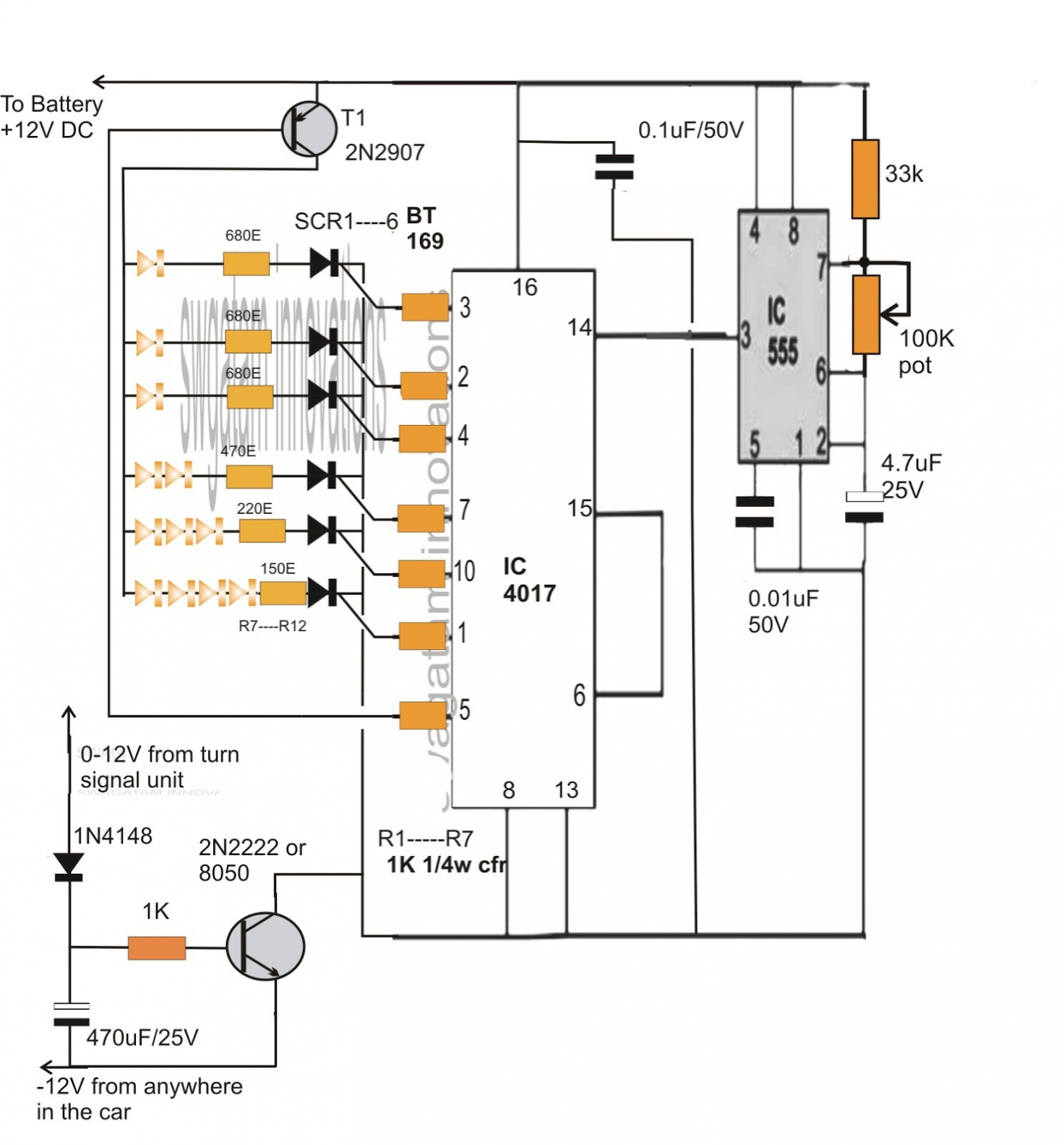
3 pin flasher relay wiring diagram. Designed with standard 3 pins, which makes your lights flash at a constant rate all the while producing a familiar “click” when signaling. EASY TO WIRE. Wiring ... 03.09.2020 · The IC 741 has been set up as a comparator where its pin#3 is assigned as the reference input while pin#2 as the sensing input. The moment the collector of the transistor goes low, the potential at pin#2 of the 741 IC becomes lower than the potential at pin#3. This instantly makes the output of the IC high, triggering the relay driver stage consisting of the another … Fuse box diagram (fuse layout), location, and assignment of fuses and relays Toyota Prius (XW30) (2009, 2010, 2011, 2012, 2013, 2014, 2015). Complete Diagnosis & Tests Technical Manual with electrical wiring diagrams for John Deere 2WD or MFWD Tractors 8100, 8200, 8300, 8400, with all the shop information to maintain, diagnose, and service like professional mechanics.. John Deere 8100, 8200, 8300, 8400 Tractors workshop Diagnosis & Tests technical manual includes: * Numbered table of contents easy to …
Question and answers Electrical Maintenance UnitQuestion and answers Electrical Maintenance UnitCT PT CC WATT METER PC Question and answers Electrical Maintenance ... A wiring diagram is a simplified conventional photographic depiction of an electric circuit. 2 pin relay wire diagram from how to wire a 3 prong flasher source h2o turbo gitarrenapotheke de 3 pin 2 cb wire diagram wiring diagram blog from how to wire a 3 prong flasher source 15 bngh eat and shape de plug wiring colors from how to wire a 3 prong ... 3 Pin Led Flasher Relay Wiring Diagram. Collection of 3 pin led flasher relay wiring diagram. A wiring diagram is a simplified conventional photographic depiction of an electric circuit. It reveals the elements of the circuit as streamlined forms, and the power and also signal links between the devices. A wiring diagram generally provides details regarding the… 3 Pin Flasher Relay Diagram | Manual E-Books – 3 Pin Flasher Relay Wiring Diagram. Wiring Diagram consists of many in depth illustrations that show the relationship of varied items. It consists of instructions and diagrams for various kinds of wiring methods and other products like lights, home windows, and so on.
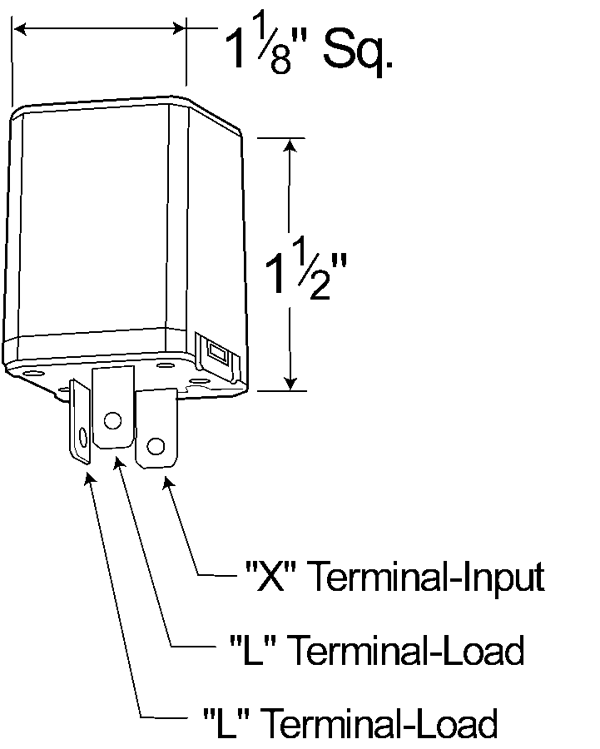
Refer to wiring diagram as a reference for installation; Made in Taiwan. Wiring: L - indicators or indicator switch; B - positive; E - negative. This solid state 3-pin relay works with both LED and regular filament type bulbs up to 180W or 15A at 12V. 12 6 Pin Flasher Relay Wiring Diagram. Wiring Diagram consists of many in depth illustrations that show the relationship of varied items. However it does not mean link between the wires. 12 volt flasher relay wiring diagram. 22.04.2021 · Hi Ron, the basic working of a compartaor op amp as shown in my diagram is very simple. The output pin 6 will be around 0 V as long as pin 3 voltage is lower than pin 2 voltage. The moment pin 3 voltage exceeds pin 2 voltage even by 0.3V will turn pin 6 high and equal to the supply voltage. 25.03.2017 · Change the pin number as according to your connection (if you are connecting an LED to the Arduino ). In this project the LED can be on and off by a keyboard input, that is simply a character or decimal input.
3 Pin Led Flasher Relay Wiring Diagram - 17
2k followers. 70 Awesome 3 Pin Relay Wiring Diagram- A govern relay is used in the automotive industry to restrict and correct the flow of electricity to various electrical parts inside the automobile. They permit a little circuit to govern a forward-looking flow circuit using an electromagnet to govern the flow of electricity inside the circuit.
Speedy Jim's Home Page, Aircooled Electrical Hints
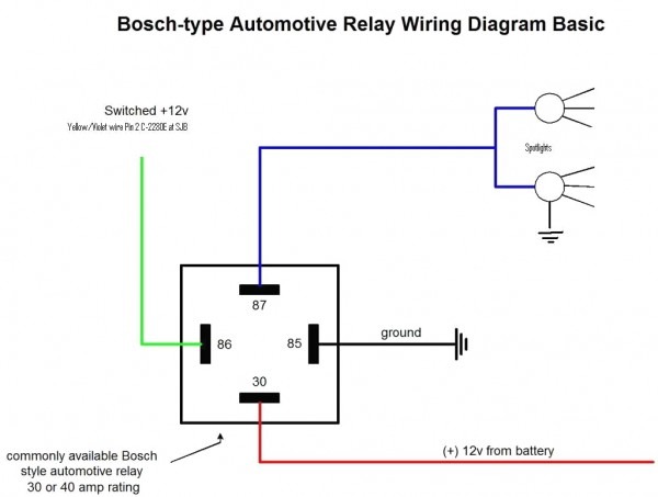
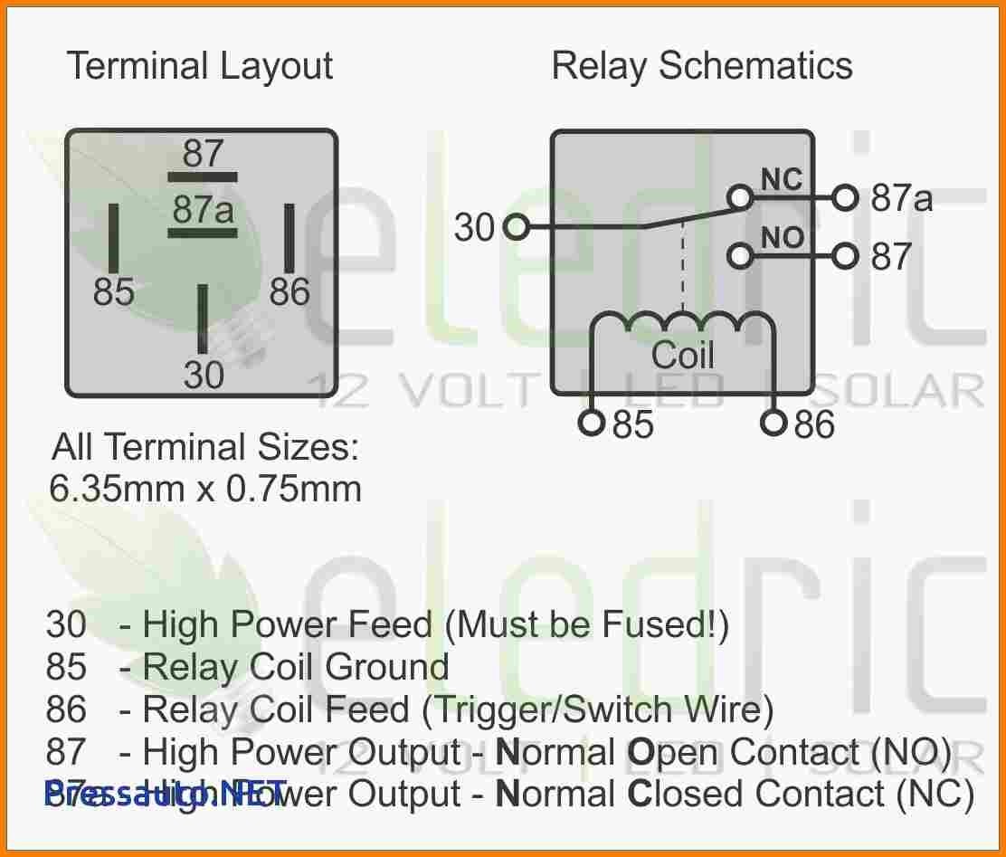
12.01.2022 · If you need to see the full relay diagram this image came from, it's here: https://www.davebarton.com ... With this type of relay, pin 87a is given power only when the relay is "OFF". Then power is switched to pin 87 when relay is activated. IN STOCK $8.00 ea. or buy 2 or more for $7.00 ea. Order Quantity ($8.00 for one) . . . . . . . . . Order Quantity (2 or …
How To Wire Up A 4 Pin Relay
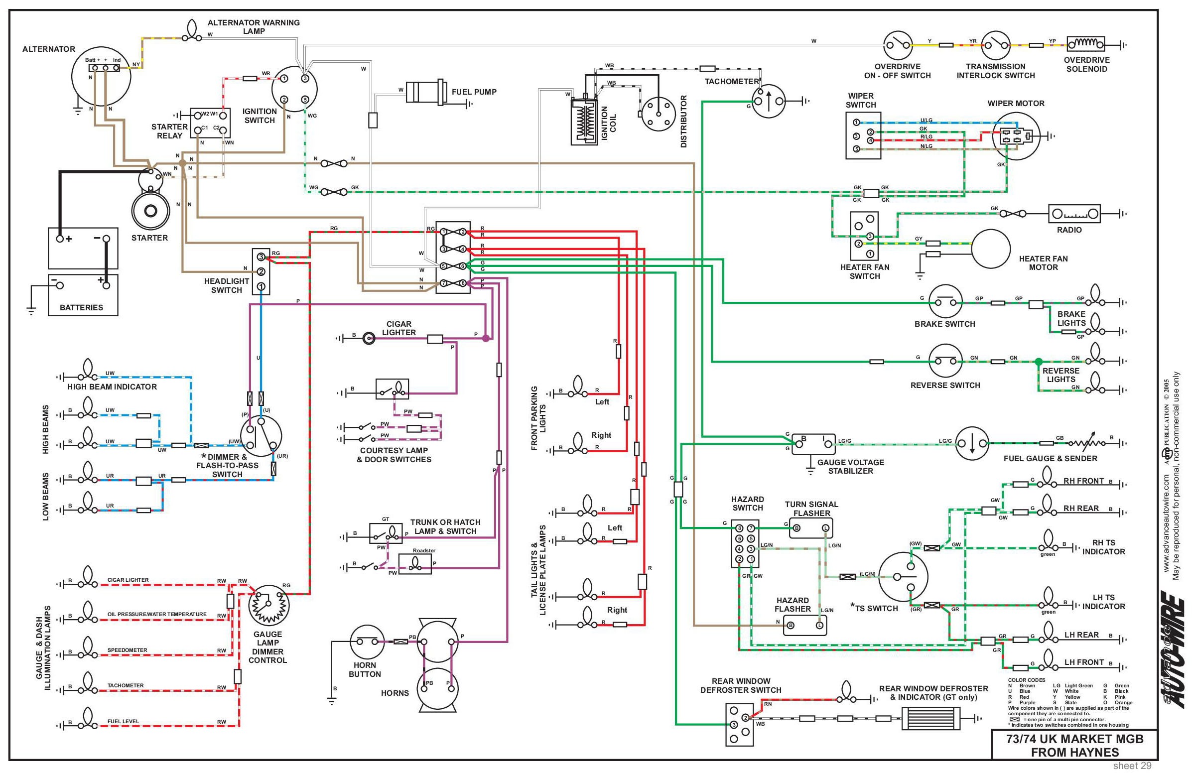
05.01.2022 · A portion of the circuit diagram showing the series relay, labeled A, is shown in the figure below. A-1119 = 2.2 ohms, A-9746 = 1.8 ohms. The A-E star rollovers energize one of the 1B-5B bank relays while simultaneously energizing the series relay. The bank relay trips to control the rollover lights. The series relay controls the scoring. [ED: It would be good to …

What Did Jesus Do?
44890. Thank you for the wiring diagram. It is a great help. Stephen P. Jun 10, 2017

electronic flasher unit wiring diagram - Wiring Diagram
3 Prong Flasher Wiring Diagram – 3 pin flasher relay wiring diagram, 3 pin flasher wiring diagram, 3 prong electronic flasher wiring diagram, Every electric arrangement is composed of various unique components. Each part should be set and connected with different parts in specific manner. If not, the structure will not work as it should be.
Diadram Wire 3 Prong Flasher | Wiring Diagram Image
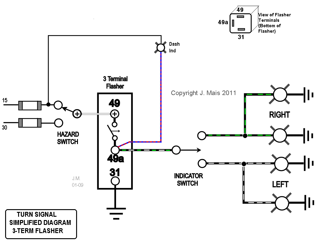
12 Volt 3 pin electronic flasher relay. Indicators: 2x21w (+5w) Hazards: 4x21w (+5w) Towing: No. Terminal 31 to Earth. Terminal 49 to Supply.

3-Pin Thermal Turn Signal Flasher Relay | MGI SpeedWare
15.10.2016 · 69892 Western Fisher 11 Pin Relay Wiring Harness Kit For 3 Port Proplus Ultramount Park Turn Signal Problem Plowsite Ford Module Wiring Wiring Diagram Western Plow Wiring Schematic Excellent Wiring Diagram Products Western 3 Port 3 Plug Wiring Kit Isolation Module Truck Side Wiring Help With 2 Plug Ultramount Plowsite Western 3 Port 3 …
How to Wire A 3 Pin Flasher | My Wiring DIagram
3 pin led flasher relay wiring diagram – A Newbie s Guide to Circuit Diagrams A very first appearance at a circuit layout might be confusing, however if you could check out a subway map, you could review schematics.
3 Pin Flasher Relay Wiring Diagram - Cadician's Blog
Dimension: 597 x 428. DOWNLOAD. Wiring Diagram Pics Detail: Name: 3 pin led flasher relay wiring diagram – lucas flasher relay wiring diagram 3 unorthodox print with wiri. File Type: JPG. Source: easela.club. Size: 50.99 KB. Dimension: 620 x 378. DOWNLOAD.
3 Prong Flasher Wiring Diagram | Wiring Diagram
11.08.2017 · 3 pin relay wiring diagram; 3 position rotary switch wiring diagram; 3 single coil wiring diagram; 3 speed table fan motor wiring diagram; 3 switch box wiring diagram; 3 way fender telecaster wiring diagram; 3 way light switch wiring diagram; 3 way switch schematic wiring diagram; 3 way switch wiring diagram light middle ; 3 way switch wiring schematic; 3 …

3 Pin 12V Flasher Relay - 20 W - Third Gear

3 Pin Flasher Relay Wiring Diagram | Fuse Box And Wiring ...

Wiring A 3 Prong Flasher Relay | My Wiring DIagram
3 Pin Flasher Relay Wiring Diagram - Cadician's Blog

Led Flasher Relay Wiring Diagram - LED Flasher Circuit ...

Led Flasher Relay Wiring Diagram - Wiring Diagram Schemas

36 Flasher Relay 3 Pin Diagram - Wiring Diagram Online Source

LED Turn Signal Flasher Relay - Mustang Evolution

3 Pin Flasher Relay Wiring Diagram | Fuse Box And Wiring ...

Three Prong 6 Volt Turn Signal Flasher Wiring Diagram ...

3 Pin Led Flasher Relay Wiring Diagram Gallery | Wiring ...

3 Pin Flasher Relay Wiring Diagram | Fuse Box And Wiring ...
Electronic Flasher Relay CF13 001 - 2allbuyer
4 Pin Flasher Relay
Wiring A 3 Prong Flasher Relay | My Wiring DIagram

Pin on Inr Wiring Diagram

Three Prong 6 Volt Turn Signal Flasher Wiring Diagram ...
3prong Flasher Wiring Diagram
Tridon Flasher Wiring Diagram - Wiring Diagram
Car blinker relay

Wiring Diagram For Vw Beetle Alternator
3 Prong Flasher | Wiring Diagram Image

Relay runner
Wiring A 3 Prong Flasher Relay | Wiring Diagram Image

Motorcycle 3 Pin Flasher Relay Wiring Diagram Manual For ...
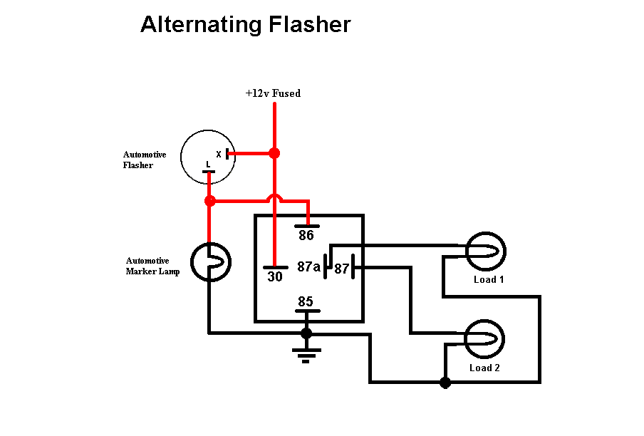
44730 - 3 Pin Flasher, 6 Light Heavy-Duty Alternating ...

Electronic Flasher Relay Wiring Diagram - Wiring Diagram ...

3 Pin Flasher Relay Wiring Diagram | Fuse Box And Wiring ...

ins:billow926

5 Pin Relay Wiring Diagram Driving Lights — UNTPIKAPPS
Comments
Post a Comment