39 compressor wiring diagram
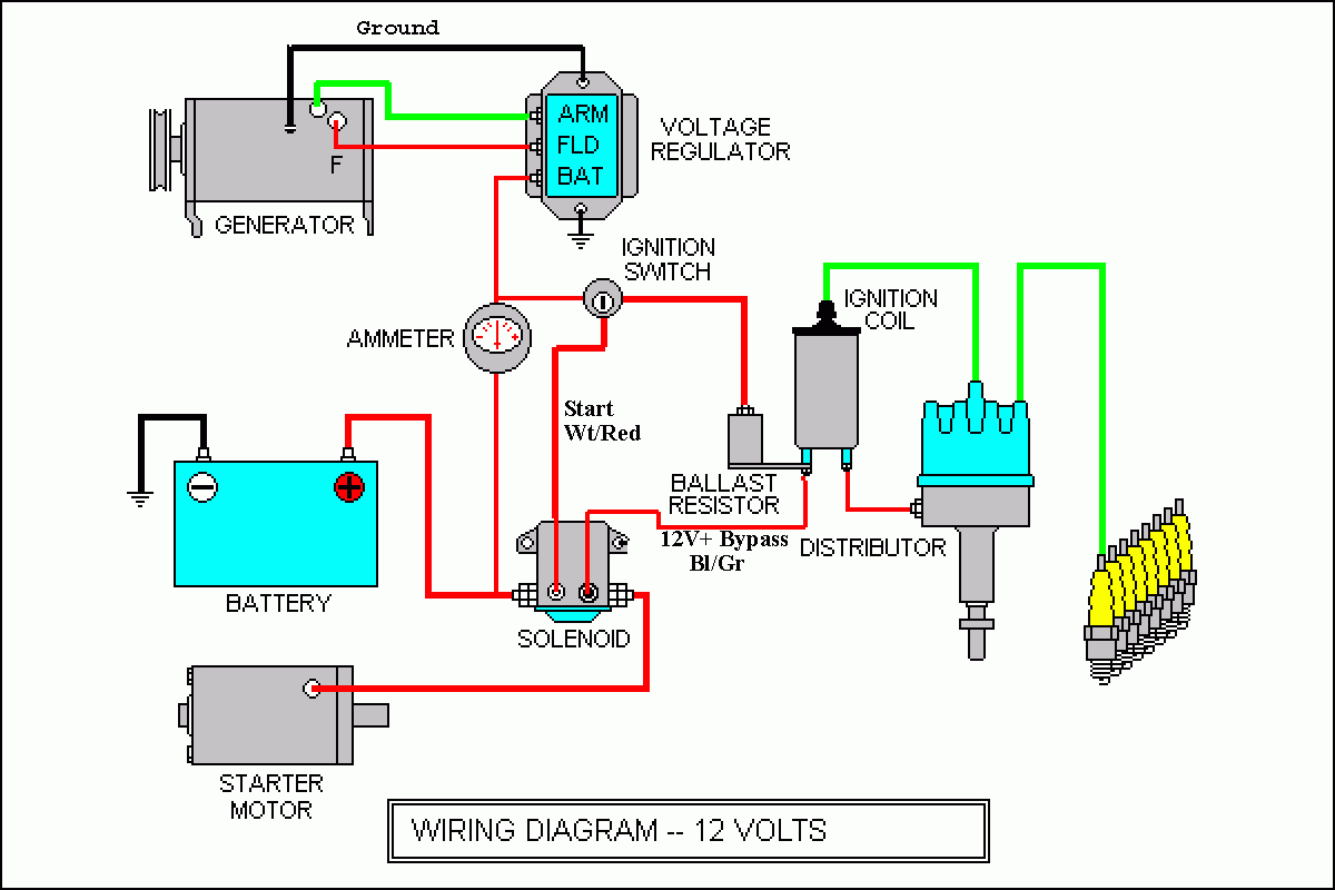
Compressor wiring diagram. At times the cables will cross. Injunction of two wires is. Honestly we also have been noticed that 3 wire 220v wiring diagram is being one of the most popular subject at this moment. Wiring A 230v Air Compressor In 2020 Diagram Electrical Circuit Diagram Diagram Design. 240 volt wiring on the flip side may not ... There are many Air Conditioning and Heat Pump brands in the market but one common component is the compressor. Most use the Copeland Compressor which usually...
Danfoss Compressor 12v Wiring Diagram. 26.12.2018 26.12.2018 5 Comments on Danfoss Compressor 12v Wiring Diagram. All 12 volt electrical wiring should be carried out according to the following table: TABLE 1 . Danfoss BD35F compressor operated fridges have a built in battery.

Compressor wiring diagram
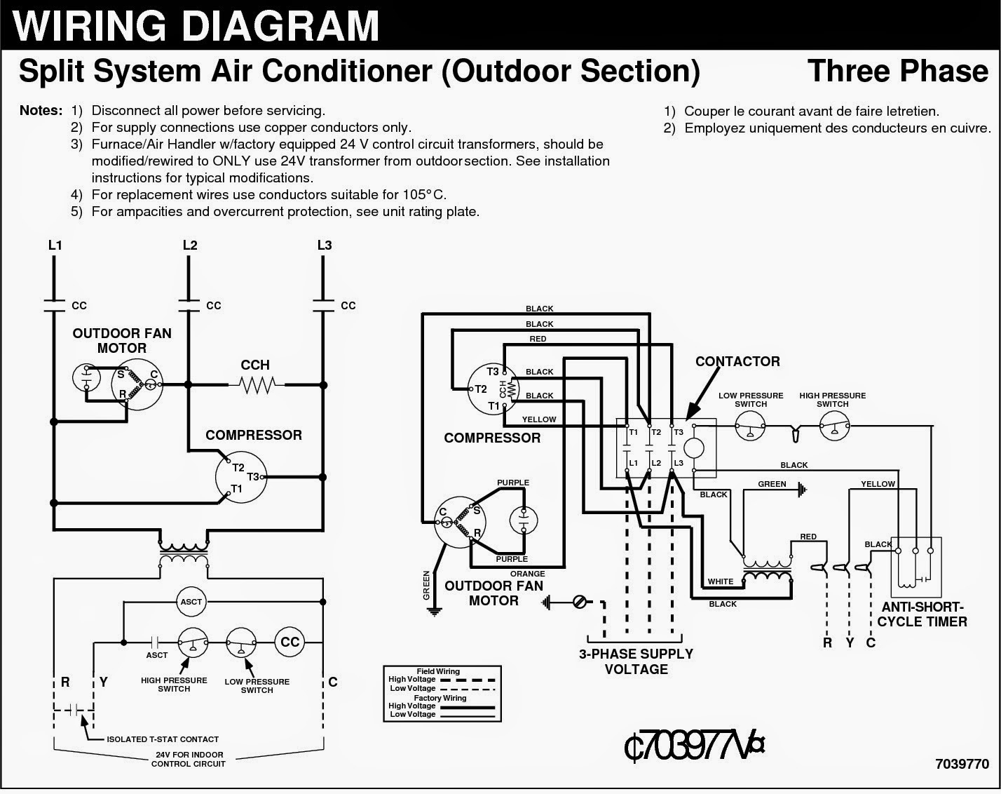
Inside the air handler unit, the high voltage wiring powers the indoor fan, the heater and provide power for the transformer. Inside the condenser/evaporator unit, the high voltage wiring powers the outside fan and the compressor. 3- Low voltage control part: This part has (2) mode for operation which are: This video contains Paid links that gives me a 6% commission if you click and buy any product on that website . This video contains Paid links that gives me ... Refrigeration Compressor Wiring Diagram | Manual E-Books - Refrigerator Compressor Wiring Diagram. Wiring Diagram not merely provides comprehensive illustrations of whatever you can perform, but also the methods you should adhere to although doing so. Not only are you able to locate various diagrams, however you also can get step-by-step ...
Compressor wiring diagram. Air Compressor Pressure Switch Wiring Diagram. Below is the Square D pressure switch wiring diagram. Connect your power lines at 1 and 3. The motor wires would connect to 2 and 4. square d pressure switch wiring diagram. FAQ (Frequently Asked Question) Compressor wiring diagram. A wiring diagram is a simplified traditional photographic depiction of an electric circuit. The standard 220 volt wiring for an air compressor includes no polarity for the red and the black wire so you cannot wire them backwards. The disconnect switch should be a 220 volt 2 pole type for both circuit wires. Atlas Copco Air Compressor Wiring Diagram. ... 25 00 picclick uk lf oil free aluminum piston le lt5 186 automotive ga30 ga37 ga45 mam 880 plc controller panel with wiring diagram 100 400a 5 132kw 180hp1 order photos pictures made in stationary auto repair software epc work compressed master catalogs zr zt 55 and 75 vsd ff oilless technologies ... Air conditioner C.S.R wiring diagram compressor start full wiring - Fully4world. 410 410Shares. student. 2k followers . Hvac Air Conditioning ... 55 New Potential Relay Wiring Diagram- A govern relay is used in the automotive industry to restrict and regulate the flow of electricity t... James Pelger.
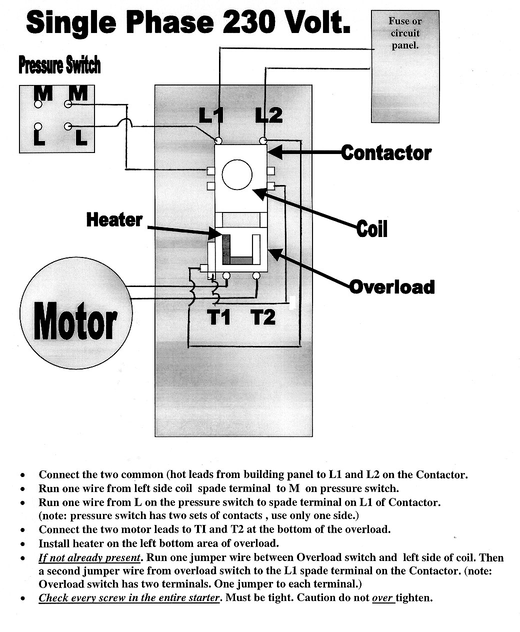
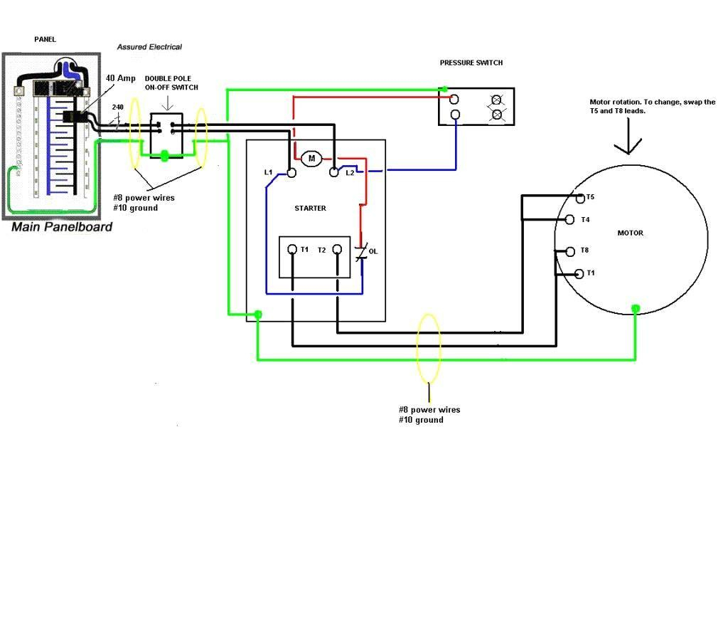
copeland compressor wiring diagram - A Newbie s Guide to Circuit Diagrams A very first look at a circuit layout may be complex, yet if you could review a train map, you could review schematics. The objective is the very same: getting from point A to aim B. Literally, a circuit is the path that allows electricity to flow. 220v compressor wiring diagram. 240 volt wiring on the flip side may not require a neutral white wire. The standard 220 volt wiring for an air compressor includes no polarity for the red and the black wire so you cannot wire them backwards. Strip 1 2 in 1 3 cm of insulation off the ends of each wire. Gt 7667 phase panel wiring diagram on single ... Aug 28, 2021 · A C Compressor Wiring Diagram – Wiring Diagrams Hubs – Compressor Wiring Diagram Wiring Diagram consists of numerous detailed illustrations that display the link of various things. It consists of instructions and diagrams for various varieties of wiring techniques as well as other products like lights, home windows, and so forth. Was looking for a wiring diagram to re-hook up my compressor in my shop at home. I disconnected the wires from the pony panel( with the on /off switch on the side) There is a black and a red wire going into the connection box for the compressor ( 220 30 amp single phase ) Reconnected the ground wire to the compressor box.
220v Air Compressor Wiring Weekend Freedom Machines. 220 240 Volt Air Compressor Wiring. 220v Supplemental Sheet Use With 97628c Installation Instructions Wiring Diagram Manualzz. Wiring diagram for 220 volt figure 7 air compressor atlas equipment ateataf7 at tooltopia doityourself ot sdway 220v 1 how do i wire my new refrigerant r134a gh14tb 3 ... According to earlier, the lines in a Air Compressor Wiring Diagram 240V represents wires. Sometimes, the cables will cross. However, it does not mean connection between the cables. Injunction of two wires is usually indicated by black dot at the intersection of 2 lines. There'll be principal lines which are represented by L1, L2, L3, and so on. Unique Wiring Diagram Ac Split Mitsubishi Refrigeration And Air Conditioning Hvac Air Conditioning Hvac Air. 55 New Potential Relay Wiring Diagram Electrical Circuit Diagram Ac Capacitor Electrical Diagram. Great Single Phase Starter Wiring Diagram A Big Compressor Throughout Air Compressor Pressure Switch Electrical Wiring Diagram Electric ... Three Phase Compressor Wiring Diagram. December 21, 2020 1 Margaret Byrd. 0. Air compressor pressure switch diagram three phase motor conductor wiring kulthorn domestic refrigerators compressors and home 3 conditioning practical machinist largest single for manual user pdf. غير مصرح عنوان البحرالابيض المتوسط Air ...
RIDGID R0230 Wiring Diagram - Air Compressor Parts Online
Help Needed Wiring Diagram For Ingersoll Rand 7 5 Caps About Air Compressors Com. Ingersoll Rand Irn100 200h 2s Irn250 300h Irn37 160k Cc Irn50 Irn75 8 4 Wiring Schematic N55 75k N75 100h A C Er Vfd. Figure 7 Air Compressor Wiring Diagram. Ingersoll Rand 2475n7 5 Fp Type 30 7 Hp 80 Gallon Two Stage Air Compressor 230v 1 Phase Fully Packaged.
Air Compressor Wiring Diagram 240V - Cadician's Blog
Voltmeter Connection Diagram For AC/DC. by Habib Ullah - 9:40 AM. This post is about the voltmeter connection diagram , in this post you will learn about wiring …. 3 Phase Wiring Diagrams.

Ge Motor Wiring Diagram Air Compressor - Wire
Compressor Wiring Diagram NE-T-J Series - CSR BOX. HomeDiagramsAir conditioner C.S.R wiring diagram compressor start full wiring. November 19, Air conditioner C.S.R wiring diagram compressor start full. While wiring a compressor, there are a number of things to consider for a proper electrical hook up. A main concern is the amperage ...

Copeland Wiring Diagrams - Wiring Data Diagram ...
Aug 06, 2020 · As stated previous, the lines in a Air Compressor Wiring Diagram signifies wires. At times, the cables will cross. But, it does not imply link between the cables. Injunction of two wires is generally indicated by black dot to the intersection of 2 lines. There will be main lines that are represented by L1, L2, L3, and so on.
Auto Ac Compressor Wiring Diagram - Cadician's Blog
Compressor Start Relay Wiring Diagram from 3.bp.blogspot.com. Print the electrical wiring diagram off plus use highlighters to be able to trace the routine. When you employ your finger or perhaps stick to the circuit along with your eyes, it's easy to mistrace the circuit. 1 trick that I actually use is to print the same wiring picture off twice.
Compressor Wiring Diagram Single Phase - Cadician's Blog
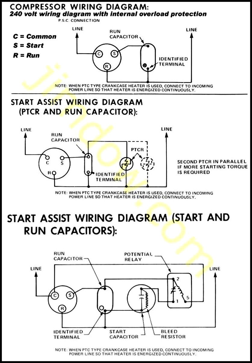
Copeland Compressor Wiring Diagram. accordance with the position of the capacitors and relay shown on the wiring diagram. Compressor model. Run capacitor. Start capacitor. Potential relay. MISWIRING IS MURDER. It is very easy to miswire a compressor, but the results can be deadly. The purpose of this booklet is to dem- onstrate how to wire a.

Embraco Compressor Wiring Diagram - Wiring Diagram And ...
copeland compressor wiring diagram - What's Wiring Diagram? A wiring diagram is a type of schematic which uses abstract pictorial symbols to show all the interconnections of components in the system.
Copeland Wiring Diagrams - Wiring Data Diagram ...
Arb Air Compressor Wiring Diagram. Print the cabling diagram off and use highlighters in order to trace the circuit. When you use your finger or even stick to the circuit with your eyes, it is easy to mistrace the circuit. A single trick that We use is to print out the same wiring picture off twice.

Copeland Compressor Wiring Diagram | Free Wiring Diagram
Inverter Compressor Wiring Diagram. Schematic of a dc inverter air conditioner 7 scientific diagram single door lg refrigerator fridge wiring primax channel ge compressor the master samurai tech academy power supply for renesas working principles solar 1 5 ton homemade circuit projects how to make exchange refrigeration club generic an with ...
Wiring Diagrams : Refrigeration : Macspares | Wholesale ...
12v Air Compressor Wiring Diagram - wiring diagram is a simplified all right pictorial representation of an electrical circuit. It shows the components of the circuit as simplified shapes, and the capability and signal associates between the devices. A wiring diagram usually gives guidance not quite the relative direction and promise of ...
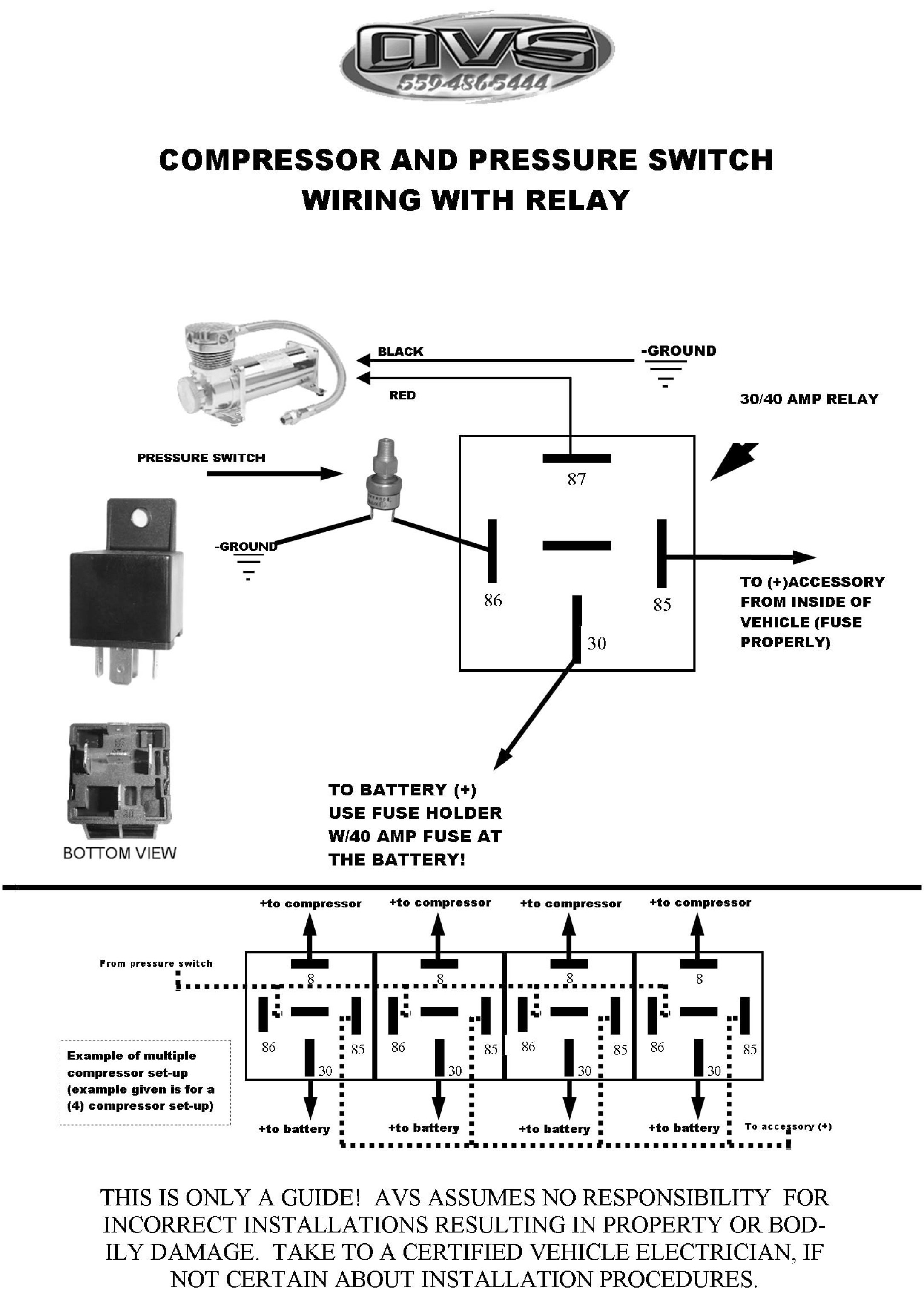
SINGLE COMPRESSOR WIRING KIT - AVS
Compressor Wiring Diagrams. PC660L Wiring Diagram; PC836L Wiring Diagram; PC990L Wiring Diagram; Ice Machine Instruction & Service Manuals; PartsConnect 2019-2020 Heating Cooling; 2020 SPRING; PartsConnect Distributors; Home / Instruction Sheets / Compressor Wiring Diagrams.

Closeup of skeleton pelvic model
Refrigeration Compressor Wiring Diagram | Manual E-Books - Refrigerator Compressor Wiring Diagram. Wiring Diagram not merely provides comprehensive illustrations of whatever you can perform, but also the methods you should adhere to although doing so. Not only are you able to locate various diagrams, however you also can get step-by-step ...

Copeland Compressor Wiring Diagram - Wiring Diagram And ...
This video contains Paid links that gives me a 6% commission if you click and buy any product on that website . This video contains Paid links that gives me ...
Embraco Compressor Wiring Diagram | Cadician's Blog
Inside the air handler unit, the high voltage wiring powers the indoor fan, the heater and provide power for the transformer. Inside the condenser/evaporator unit, the high voltage wiring powers the outside fan and the compressor. 3- Low voltage control part: This part has (2) mode for operation which are:

Air Compressor Wiring Diagram 230v 1 Phase - General ...

Closeup of skeleton hand model

Find Out Here Porter Cable 60 Gallon Air Compressor Wiring ...

Compressor Start Capacitor Wiring Diagram
19 Images Copeland Scroll Compressor Wiring Diagram

Air Compressor Pressure Switch Wiring Diagram - Collection ...

Wiring Diagram Ac Capacitor - Home Wiring Diagram

Basic Compressor Wiring - YouTube
Wiring Diagram For Air Compressor Motor | Wiring Diagram
Basic Compressor Wiring - Youtube - Ac Compressor Wiring ...

Copeland Scroll Compressor Wiring Diagram

41 Ingersoll Rand Air Compressor Wiring Diagram 3 Phase ...

Resistor De 220 Volts

Wiring Diagram For Danfoss Compressor | schematic and ...
Air Compressor Pressure Switch Wiring Diagram - Cadician's ...
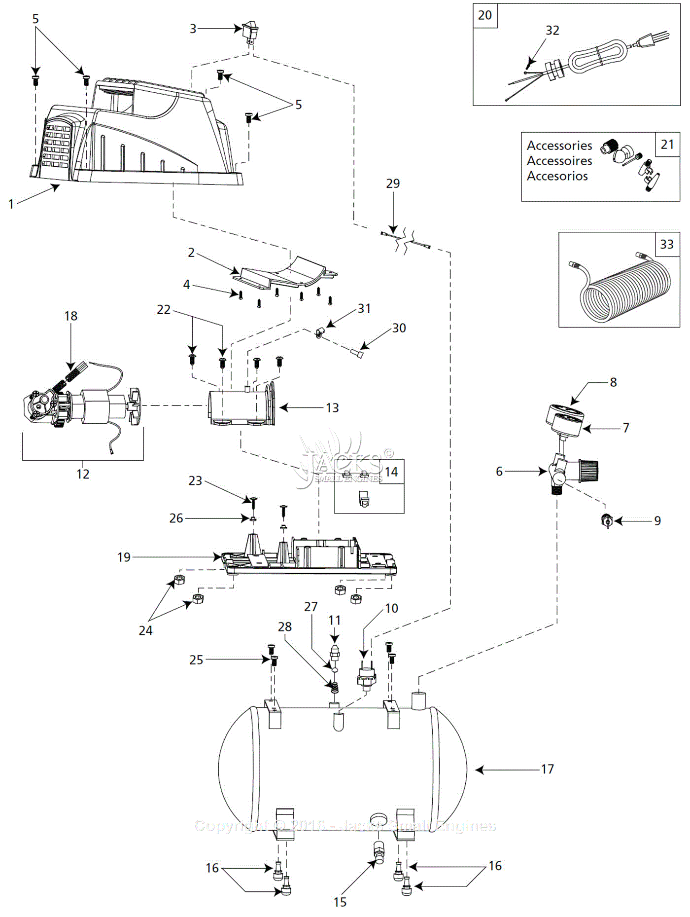
Campbell Hausfeld FP209402 Parts Diagram for Air ...

28 Copeland Compressor Wiring Diagram Single Phase - Wire ...

Refrigeration and Air Conditioning Repair: July 2013

29 Wiring Diagram For Air Compressor Pressure Switch ...

Embraco Wiring Diagram - Wiring Diagram And Schematic ...

Copeland Compressor Wiring Diagram | Free Wiring Diagram

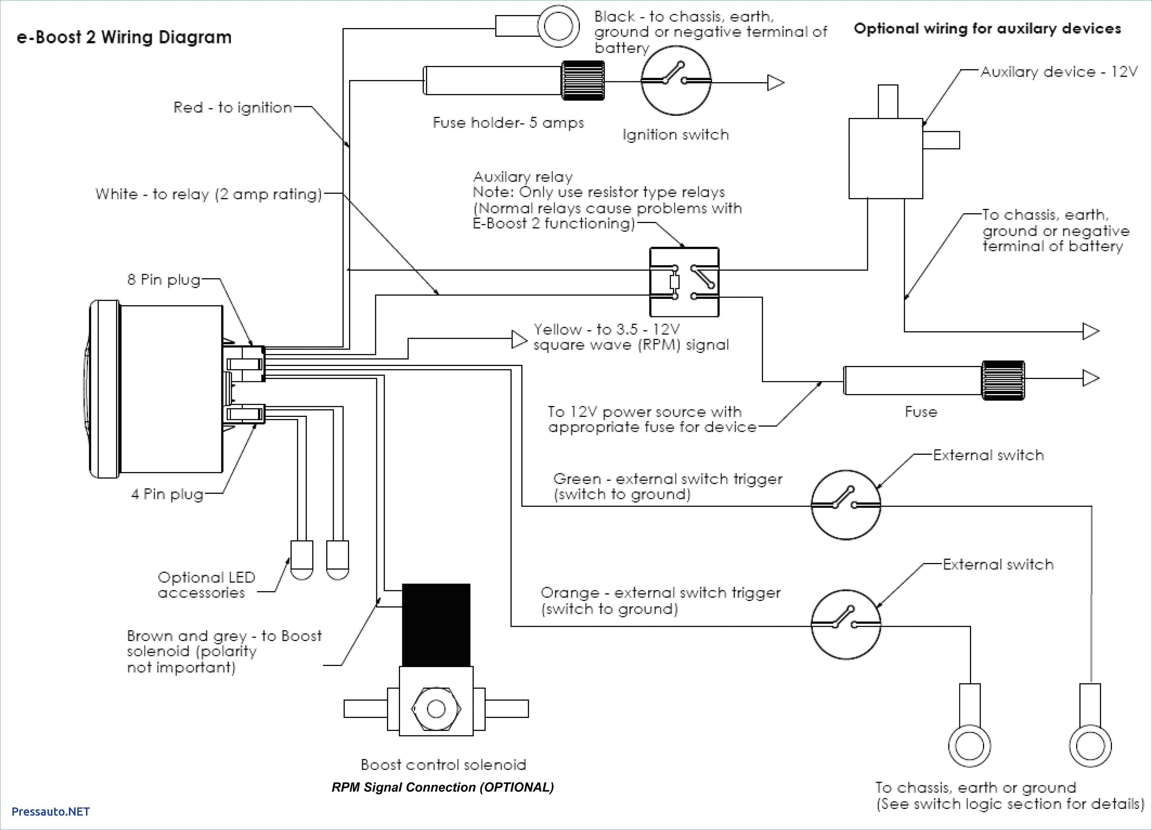
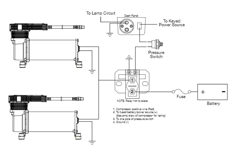
(Wiring Diagrams) Air Ride Compressor

Copeland 3 Phase Compressor Wiring Diagram
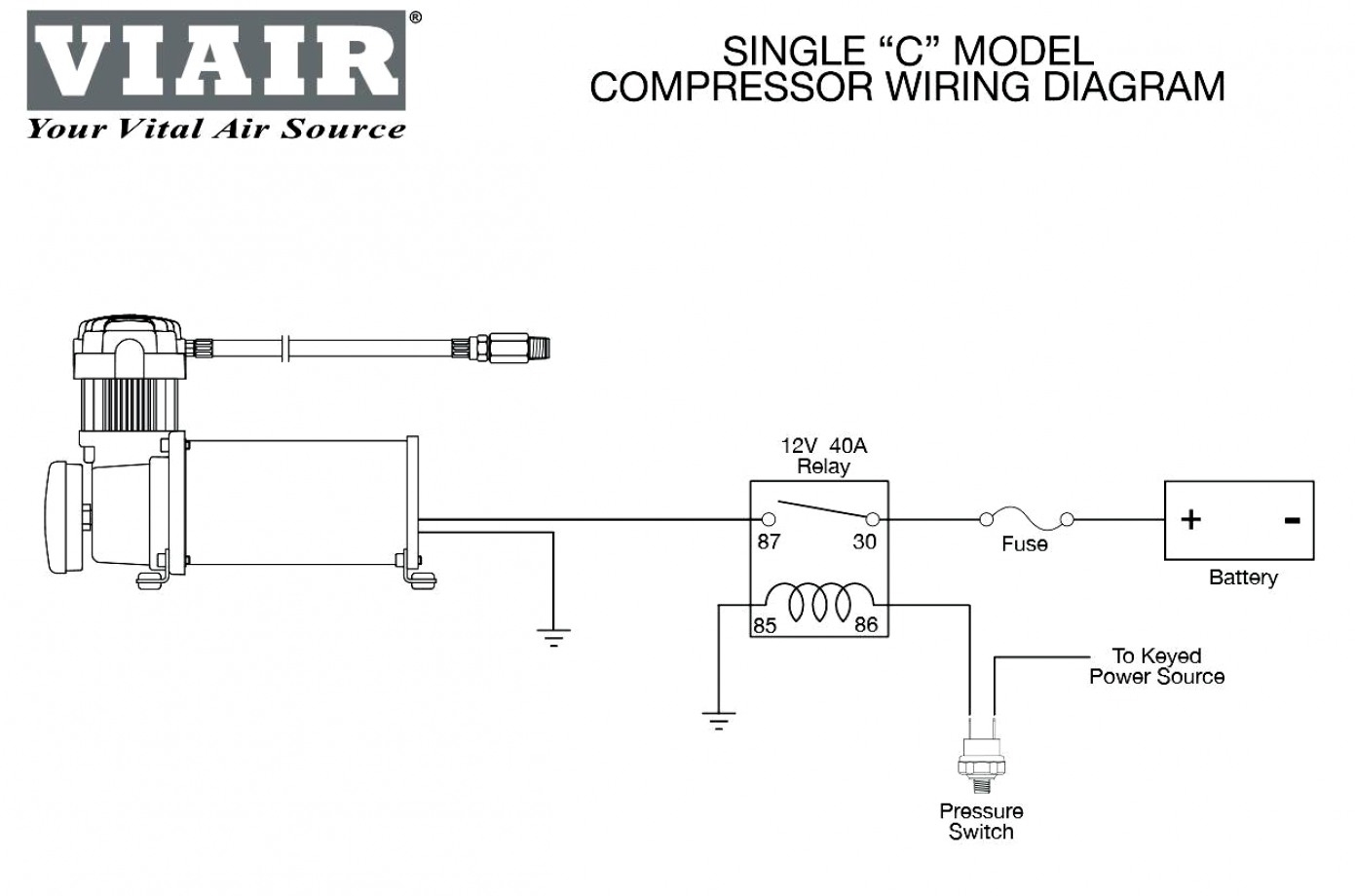
Viair Compressor Wiring Diagram - Complete Wiring Schemas
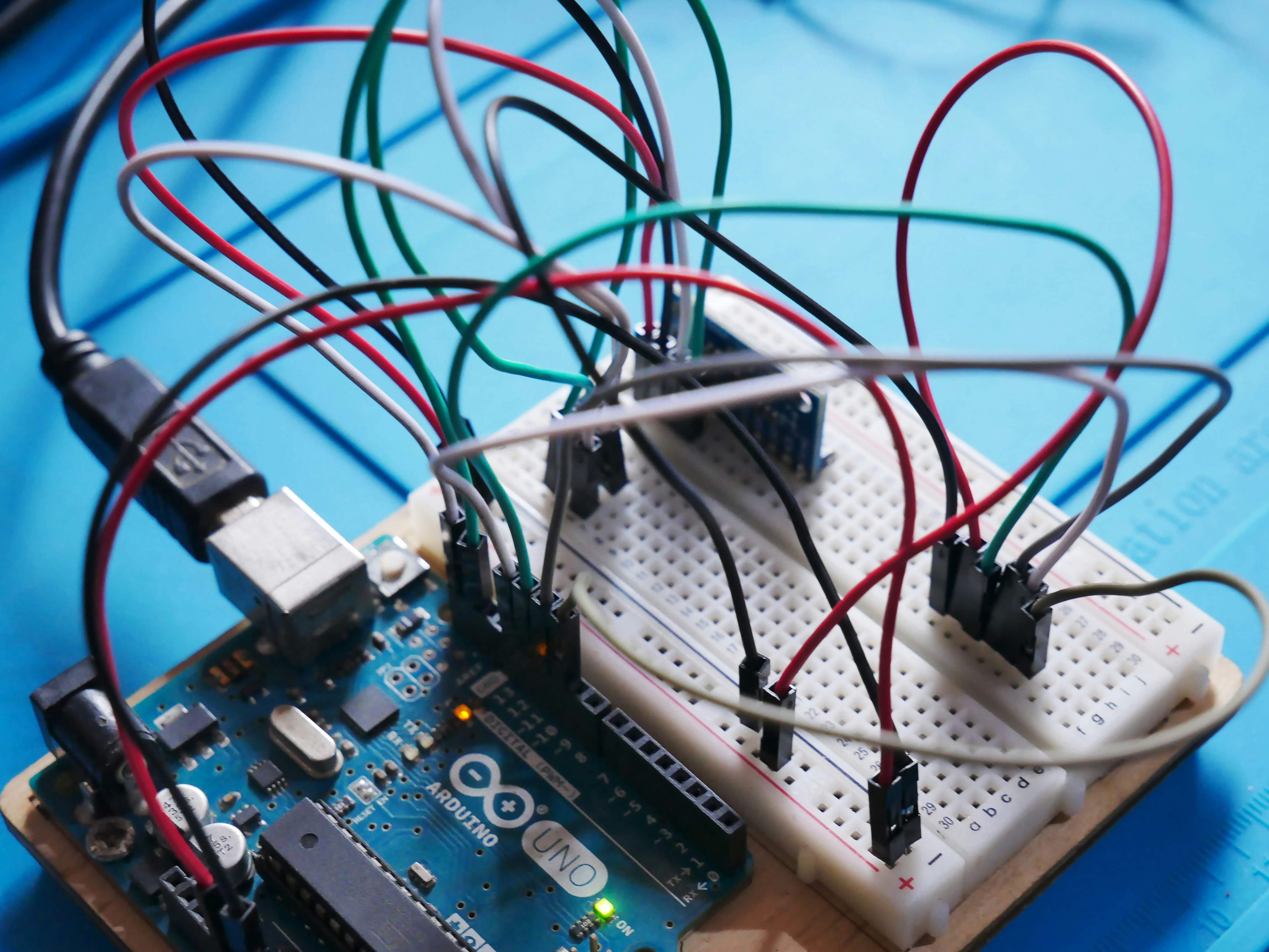
An Arduino Uno board wired to a couple of sensors on a breadboard.
Comments
Post a Comment