39 ac relay wiring diagram
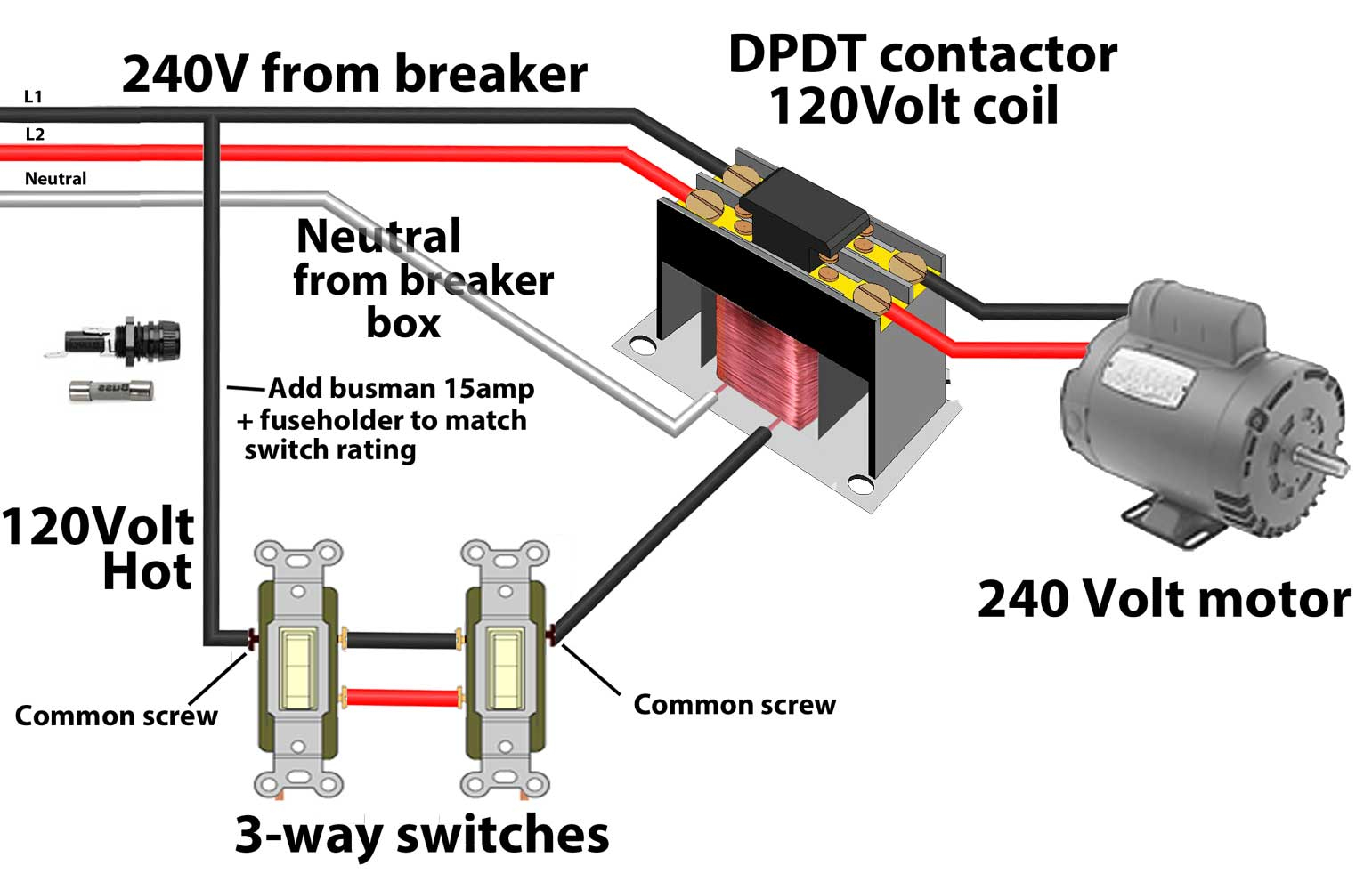
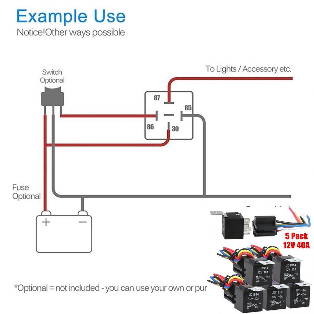
Ac Contactor Wiring Diagram Sample. Collection of ac contactor wiring diagram. A wiring diagram is a simplified traditional pictorial representation of an electrical circuit. It shows the elements of the circuit as simplified shapes, as well as the power as well as signal connections in between the devices. A wiring diagram usually offers details about… This diagram will show you how simple it is to control motors, lights, valves, other relays and any type load you want. In this example we are simply turning on a light. Let's say were using household voltage in this circuit which is 110/120 Vac. L1=Hot and L2=Neutral.
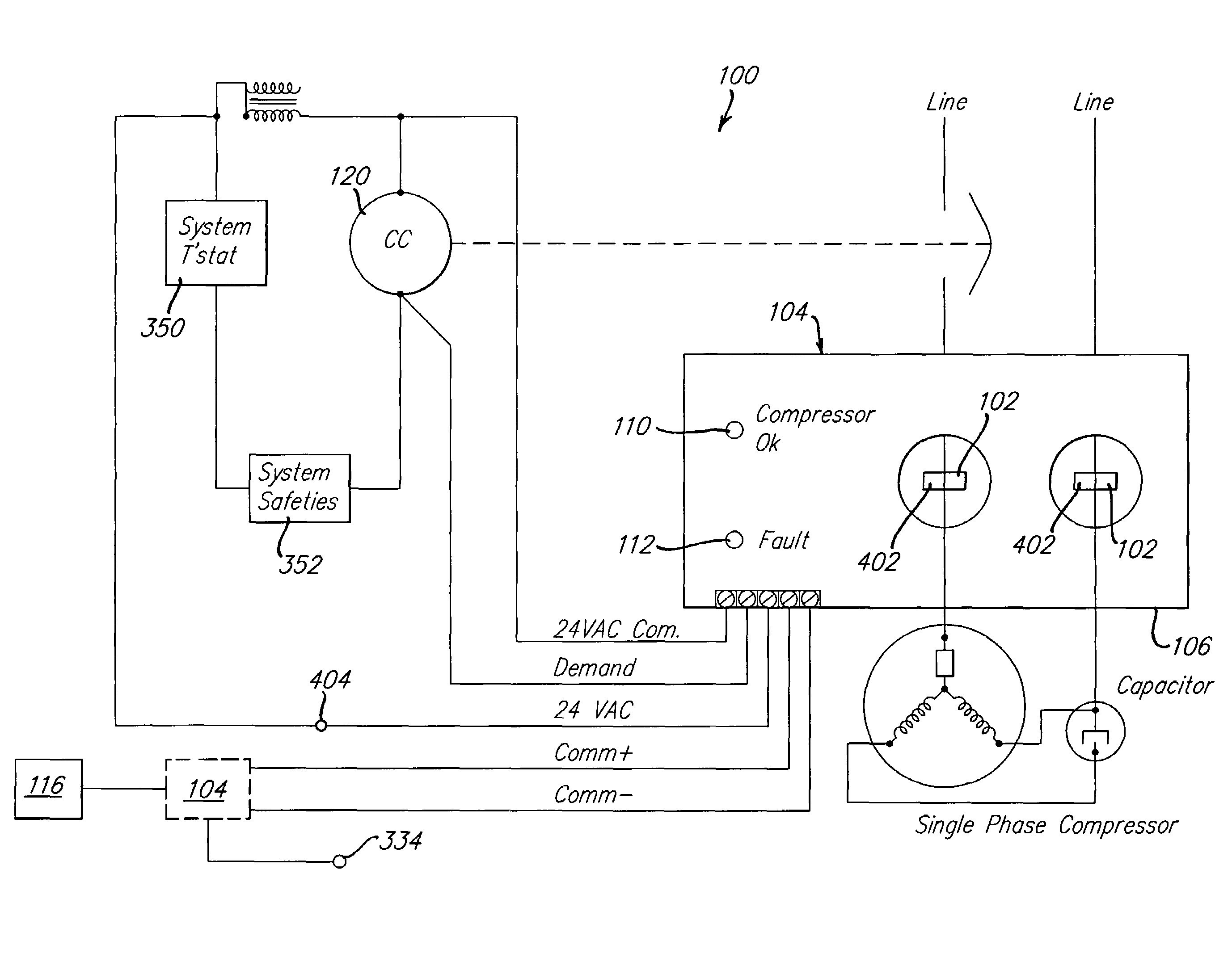
In the above split unit contactor wiring diagram, all wiring connections are shown, the magnetic contactor is used as an on/off switch for the compressor. The PCB circuit relay controls the compressor magnetic contactor and the magnetic contactor will control the compressor.
Ac relay wiring diagram
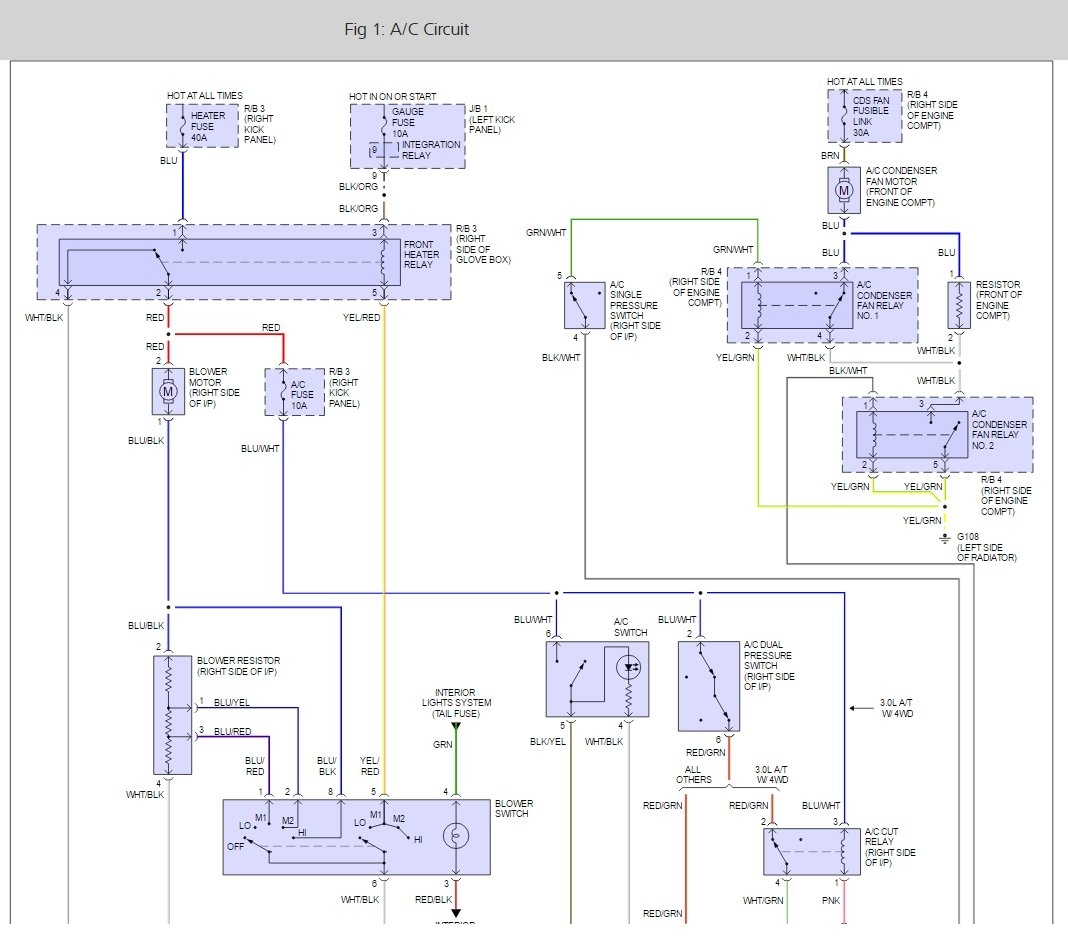
3- Types of Electrical Wiring Diagrams For Air Conditioning Systems There are three basic types of wiring diagrams used in the HVAC/R industry today, which are: The Ladder Diagram, The Line Diagram, The installation diagram. 3.1 The Ladder Diagram It is the most common type of wiring Diagrams. Fig.7: Window Air Conditioning Unit Electrical Wiring Diagrams - Touch and Remote Control Type 1.4 The power flow inside a Typical Window air conditioning unit in the cooling mode When you turn the selector switch to cool mode, the power that came in from the cord that connected to the selector via hot wire goes to the fan so the fan operates. Air Conditioning 1st Stage Heat (White) 2nd Stage Heat Some AC Systems will have a blue wire with a pink stripe in place of the yellow or Y wire. 5 This diagram is to be used as reference for the low voltage control wiring of your heating and AC system. Always refer to your thermostat or equipment installation guides to verify proper wiring.
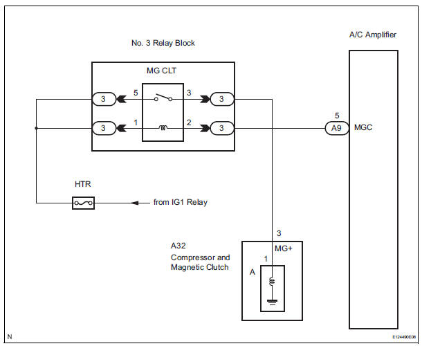
Ac relay wiring diagram. Aug 12, 2021 - 55 New Potential Relay Wiring Diagram- A govern relay is used in ... Unique Wiring Diagram Ac Split Mitsubishi Basic Electrical Wiring, Ac ... How to Wire AC Compressor Clutch Relay - YouTube. Pin 1 and 2 marked on the relay image are pin 1 and 3 in the diagram and pin 3 and 4 marked on the relay are pin 2 and 4 on the diagram. The plug is called A15. If you look directly at it with the relay removed and the clip facing up the pins in the diagram are. 1 Top Left Yellow with Blue 2 Top Right Yellow with Blue 3 Bottom Left Blue with Orange press x to close. r. Griffin Thermal Products. Menu. Home. Griffin Radiators. Exact Fit · Performance Fit · Combo Unit · Universal Fit · Custom Radiator.
Various Relay Wiring Diagrams. Below are the diagrams for connecting the various types of relays. This list covers Single Pole Single Throw (SPST) Relays, Single Pole Double Throw (SPDT) relays, and Double Pole Double Throw (DPDT) relays. Each of the different types of relays have different configurations (as they have different numbers of pins). Electric Fan Relay Wiring Diagram - Wiring Block Diagram - 5 Pin Relay Wiring Diagram Wiring Diagram includes numerous comprehensive illustrations that show the relationship of varied things. It contains directions and diagrams for different varieties of wiring strategies and other things like lights, windows, and so on. May 22, 2020 - 50 Luxury 90340 Relay Wiring Diagram- A manage relay is ... Wiring Type-2 Basic Electrical Wiring, Electrical Circuit Diagram, Ac Wiring,. & Wiring Diagram. The Dometic Single Zone Liquid Crystal Display(SZLCD) PN's . CONNECTING V AC TO THE SZLCD CONTROL RELAY BOX WHETHER YOU. Dometic Corporation .. B. Air Distribution Box Wiring Diagram This air conditioner (hereinafter referred to as "unit" or "product") is design and intended for. Installation and Operating Manual ..
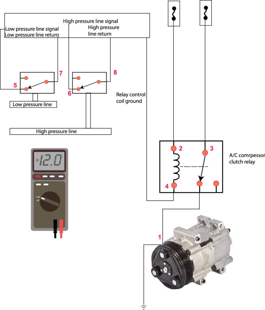
When the relay is energized, that line with the arrowhead, moves to terminal 87, that circuit carries voltage to ac compressor. At the ac compressor, dark green wire is voltage, black is ground. You have to have both. You might be ahead to check for hvac trouble codes. Might need to know the pressures on the gauges. Marine accommodation air conditioner piping diagram. The motor is 3 phase and it appears to be wired according to the diagram for the low voltage 220. Before you wire a 230v air compressor you should always check the manual for the proper wire gauge. Car air conditioner electrical wiring. Voltmeter Connection Diagram For AC/DC. by Habib Ullah - 9:40 AM. This post is about the voltmeter connection diagram , in this post you will learn about wiring …. 3 Phase Wiring Diagrams. wiring diagram- gen ii compac unit (required) compressor safety switch binary type blue blue 87 87 87a 87a 86 85 86 85 30 30 pink blue blue red red red/white grey/black white/yellow white/yellow red/white red black b b l h l h m ac m ac yellow orange orange orange yellow yellow ground ground purple heater control valve potentiometer aux. bat. whitepurple white black orange brown red lt.
Wiring Diagram Potential Relay - HENWRITHINGS
Option: Air Conditioner Relay Diagram 85 87 86 30 Orange Wire: To A/C Compressor Wire/Trinary Switch Vehicle Ground Red Wire: To Grey Wire/Temperature Sender Additional Relay required – not supplied in kit. A/C Compressor will send “ground” signal to Temperature Sender to turn fans “on”. 87 A Connect Yellow and Grey wires to ground.
SSR-A1241 Solid State Relay (41 Amp, 80-240 V AC Input, 80 ...
When I turn on the air, the blower motor comes on, but the AC clutch does not engage. I replaced the clutch cycling switch and toped off the R134 so the pressure is good (around 55 at 90 degrees) . I can get the ac to run cold when I jumper wire the positive side of the compressor. I then figured it was the AC relay.
Ac Contactor Wiring Diagram | Cadician's Blog
Safety Light Curtains Xu Wiring Diagram Of The Association Xusl4e Curtain And Xpsuaf Relay Schneider Electric Global. Schneider Electric Legacy Relays 792xdx3m4l 24d Ice Cube Relay 3a 4dpt 24vdc Plug In 300v Full Featured Cover 792 Control Allied Electronics Automation.
Wiring diagram for a 12V 40 Amp relay - Harley Davidson Forums
8 pin relay wiring diagram - You will want a comprehensive, professional, and easy to know Wiring Diagram. With such an illustrative guide, you'll be capable of troubleshoot, stop, and complete your tasks easily. Not merely will it help you attain your desired results quicker, but also make the complete procedure less difficult for everybody.

person holding red metal frame
Sep 27, 2020 - 15+ Car Ac Relay Wiring Diagram - Car Diagram - Wiringg.net.

white spiral paper on black surface
55 New Potential Relay Wiring Diagram. 55 New Potential Relay Wiring Diagram- A govern relay is used in the automotive industry to restrict and regulate the ...
Ac Compressor Relay Wiring Diagram - Wiring Diagram
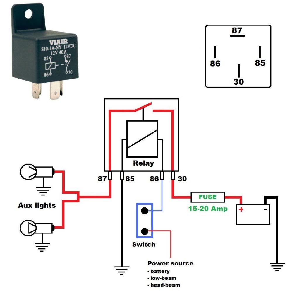
The diagram above is the 5 pin relay wiring diagram. There are different kinds of relays for different purposes. It can be used for various switching. Relay can be the best option to control electrical devices automatically. 5 pin is compromised of 3 main pins and an SPDT (single pole double throw).
Viewing a thread - John Deere 4430 lost radio and air ...
Oct 28, 2021 · How to wire a relay vg ac 24vac sprinkler board driving 24v by 220v supply relays work diagrams oono dpst 1no 1nc 8amp power dpdt 24vdc 5a 8 pin terminals connect in circuit sl 2sw ctrl dual latching coil schematic general hvac training on electric heaters 12v 110v dc volts 10a 120v wiring 24 volt switch using rib control bathroom does this diagram push up and or taco sr503 4 three zone switching interposing plc system single pole double throw spdt c changeover four furnace fan limit pilz ...
yellow blue and black coated wires
> circuits > 5 Volt RelayCircuit for Controlling AC Current l54713 . This circuit is under:, circuits, 5 Volt RelayCircuit for Controlling AC Current l54713 The following schematic shows the Relay Wiring Circuit Diagram for controlling an Air Conditioner or other higher high-current device from a microcontroller..

Where is the ac relay located on a 2001 toyota tundra ...
AC System function, adding relay to clutch wire Addition of relay to operate air conditioning compressor In a separate PDF in this section of the website there is a wiring diagram which shows the installation of a relay in the ‘Air Conditioning Compressor Clutch’ circuit. It is a helpful addition to units that have an air conditioning ...
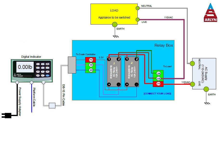
AC Solid State Relay - Wiring Diagram - Arlyn Scales
Dec 5, 2019 - 15+ Car Ac Relay Wiring Diagramcar ac relay wiring diagram,Car Diagram - Wiringg.net.

Want to know if you can give me a wiring diagram from the ...
Ac Relay Wiring Diagram- wiring diagram is a simplified pleasing pictorial representation of an electrical circuit.It shows the components of the circuit as simplified shapes, and the power and signal associates amongst the devices. A wiring diagram usually gives guidance practically the relative twist and deal of devices and terminals upon the devices, to back in building or servicing the ...

Aprilaire 700M and Armstrong Ultra 80 furnance ...
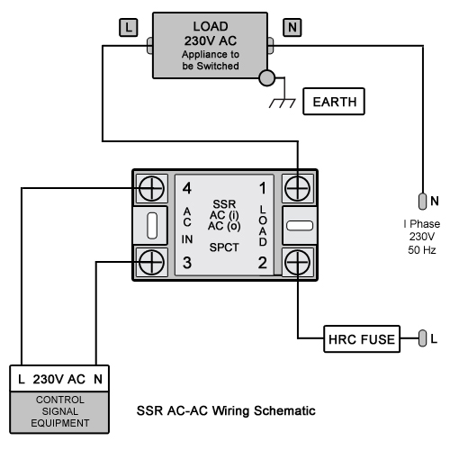
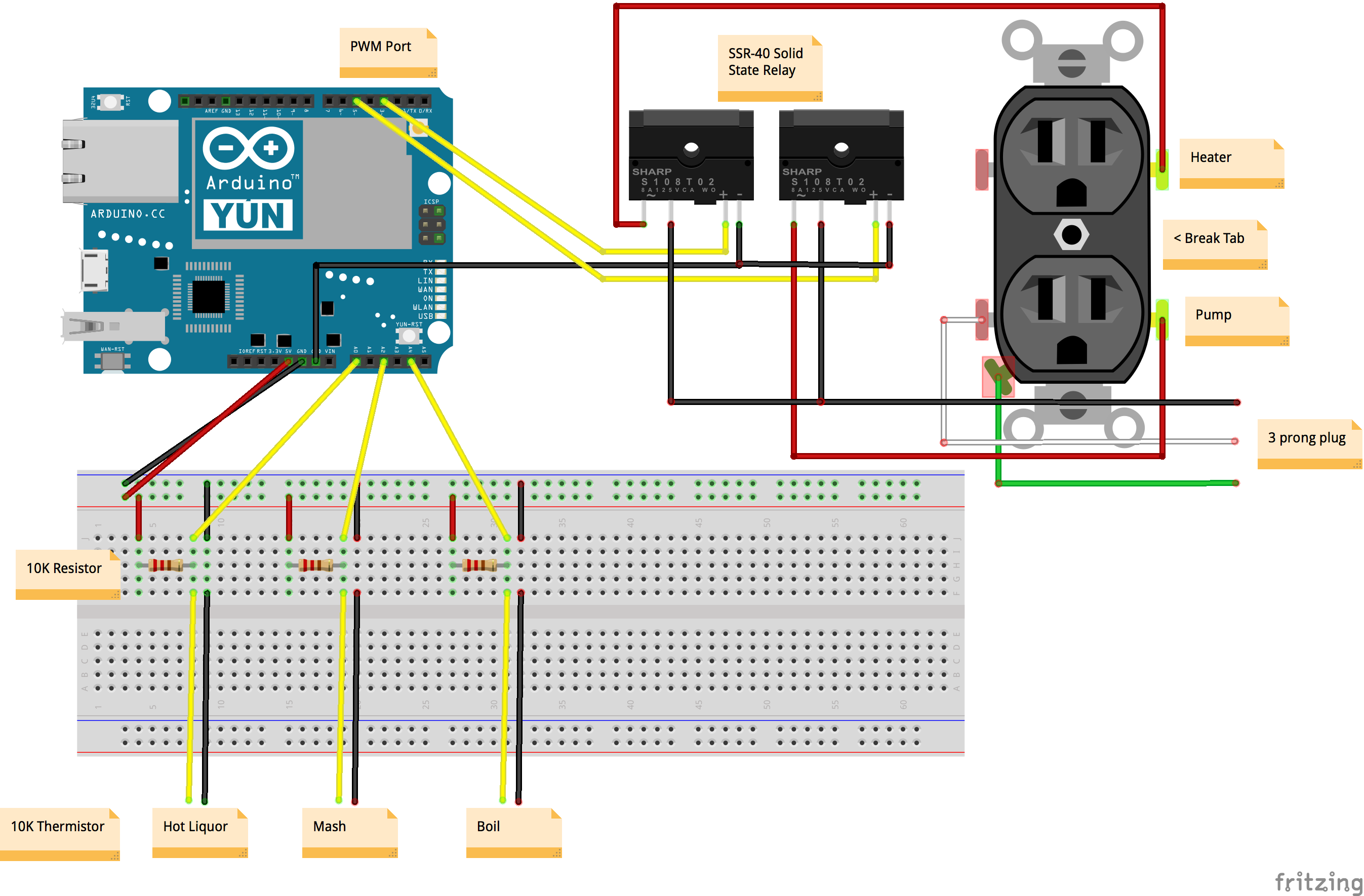
This diagram shows how to wire the AC Solid State Relay to your system. Your system may come with one or more relays. In this example, a two relay box is used as an illustration. Only one relay is shown wired. The other relays should be wired in a similar fashion. The diagram assumes customer supplied voltage of 110VAC but it can go up to 240VAC ~ 10A.

Volkswagen Jetta Dropping Relay Center - Part 3 - YouTube
30 Unique Refrigerator Start Relay Wiring Diagram- A control relay is used in the automotive industry to restrict and tweak the flow of ele... Brandon KiddAir ...
Ac Wiring Relay - Wiring Diagram Networks
Wiring diagram 3 Voltage range 3 Cable dimensions 3 Thermostat connection 4 Compressor speed 4 Fan connection 4 Troubleshooting 4 LED. Relay switch wiring diagram ac. 87 A Connect Yellow and Grey wires to ground. 460v To 230v Wiring Diagram Three Phase Voltage.Ac Relay Wairig Refrigeration And Air Conditioning Hvac Air Conditioning Electrical Circuit Diagram.

Ac Relay Wiring
Air Ride Relay Wiring Diagram. Using switch wiring diagram run wires from assigned valves to switches with each valve solenoad being grounded at valve location. 1 - Connect the red power wire directly to the battery. Hydrauliccars Hydraulic Cars Lowrider Air Ride Hydraulic Cars Air Conditioning System Design.

Need to know where ac fuse and relay are located for 93 ...
Here is a wiring diagram for the AC compressor. HOwever the wires do not attach to the low side pressure switch. The low side pressure switch gives a signal to the computer and the computer cycles the compressor relay to turn it on.
Jd1914 Relay Wiring Diagram - LIZAMOI
Dec 27, 2017 · Ac compressor won t run ricks free auto repair advice automotive tips and how to a c clutch relay function troubleshooting ford escape wiring diagram 2 wires hook up what allpar forums for android car help el camino central forum replace an air conditioning yourmechanic conditioner solution eg2repair in bbs technologies library 381d73 basic facebook 2011 mazda 3… Read More »
Wiring Safely: Fan Relay Wiring With C&R Racing
WRG 8228] Potential Relay Wiring Diagram Hvac Air Conditioning, Split Ac, Electronic Parts. Micheleradiowiring. Michele F. Jordan | Radio wiring diagram |.

Ac Wiring Diagram Ford Blower Motor Diagram Heat - Wiring ...
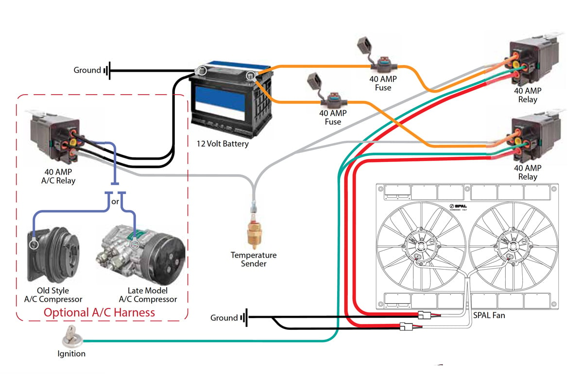
temp sensor and A/C relay. These diagrams show the use of relays, ON/OFF sensors, ON/OFF switches and ON/OFF fan controllers. Nothing here should be confused with the latest generation of PWM VARIABLE SPEED CONTROLLERS, which have much higher technology, such as a soft start feature and smooth ramping, but not necessarily better durability. HAYDEN
A/c Relay Location: Exactly Where Is the A/c Compressor ...
Air Conditioning 1st Stage Heat (White) 2nd Stage Heat Some AC Systems will have a blue wire with a pink stripe in place of the yellow or Y wire. 5 This diagram is to be used as reference for the low voltage control wiring of your heating and AC system. Always refer to your thermostat or equipment installation guides to verify proper wiring.

IMG_0038
Fig.7: Window Air Conditioning Unit Electrical Wiring Diagrams - Touch and Remote Control Type 1.4 The power flow inside a Typical Window air conditioning unit in the cooling mode When you turn the selector switch to cool mode, the power that came in from the cord that connected to the selector via hot wire goes to the fan so the fan operates.
Wiring Diagram For Solid State Relay
3- Types of Electrical Wiring Diagrams For Air Conditioning Systems There are three basic types of wiring diagrams used in the HVAC/R industry today, which are: The Ladder Diagram, The Line Diagram, The installation diagram. 3.1 The Ladder Diagram It is the most common type of wiring Diagrams.

55 New Potential Relay Wiring Diagram | Electrical circuit ...

Image from page 72 of "A report on the alternating current, single phase, interurban railway line between Bloomington and Peoria" (1909)
Hournine Racecraft - Bosch Normal Relay Wiring
2012 Nissan Altima Ac Relay Location ~ Perfect Nissan

silhouette of wind turbines during sunset

Old Lennox unit not working!?? - DoItYourself.com ...

silver and black round coins

Best Relay Wiring Diagram 5 Pin Wiring Diagram Bosch 5 Pin ...

Want to know if you can give me a wiring diagram from the ...

man on running field

gray concrete building

Ac Wiring Dual Electric Fan - Wiring Diagram Networks

MGR mager solid state relay wiring diagram |HUIMULTD

Air Conditioning Contactor Wiring - Wiring Diagram Networks

230v Relay Wiring Diagram

Trane XE900 contactor wiring
Comments
Post a Comment