38 truss bridge force diagram
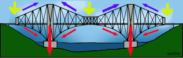
one to determine forces in specific truss members directly. Method of Sections ≡ involves cutting the truss into two portions (free body diagrams, FBD) by passing an imaginary section through the members whose forces are desired. Desired member forces are determined by considering equilibrium of one of the two FBD of the truss. Cable-stayed bridge. A cable-stayed bridge is similar to a suspension bridge. However, the deck hangs directly from the piers on cables. The piers are in compression and the cables are in tension. The deck experiences both forces. Truss bridge. A truss bridge is a variation of a beam structure with enhanced reinforcements. The deck is in tension.
The force of which pulls along the axis of a member, causing failures by ripping apart the members from the gusset plates along the bridge. This force is crucial to keep in mind when building the structure for a truss bridge. Often in diagrams this is represented as the color red.

Truss bridge force diagram
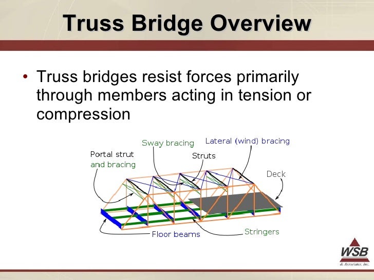
This instructable will go over how to correctly analyze a truss bridge using the method of joints. This technique is common in civil engineering practice. The purpose of this analysis is to take into account the structure, supports, and loads, and calculate the forces within each member of the truss. The major components of a typical truss bridge are illustrated in the two diagrams below. The elevation view shows the bridge from the side. The isometric view is a three-dimensional representation of the structure. Note that certain members are only visible in the isometric view. 1-2 A typical truss bridge. This free online roof truss calculator is a truss design tool that generates the axial forces, reactions of completely customisable 2D truss structures or rafters. It has a wide range of applications including being used as a wood truss calculator, roof truss calculator, roof rafter calculator, scissor truss calculator or roof framing.
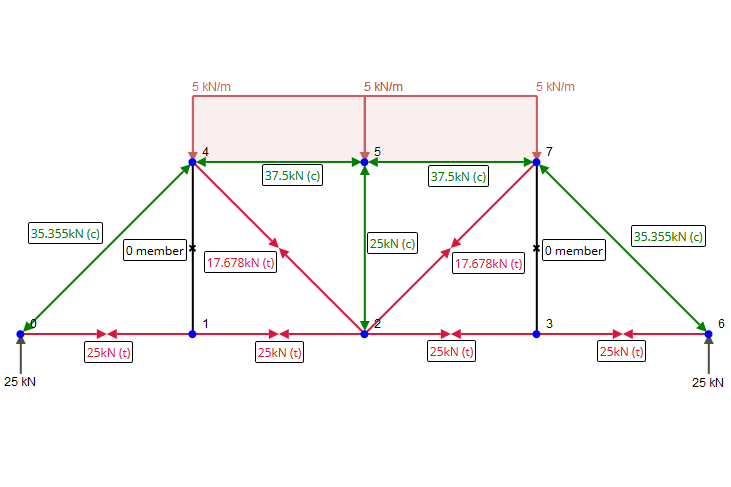
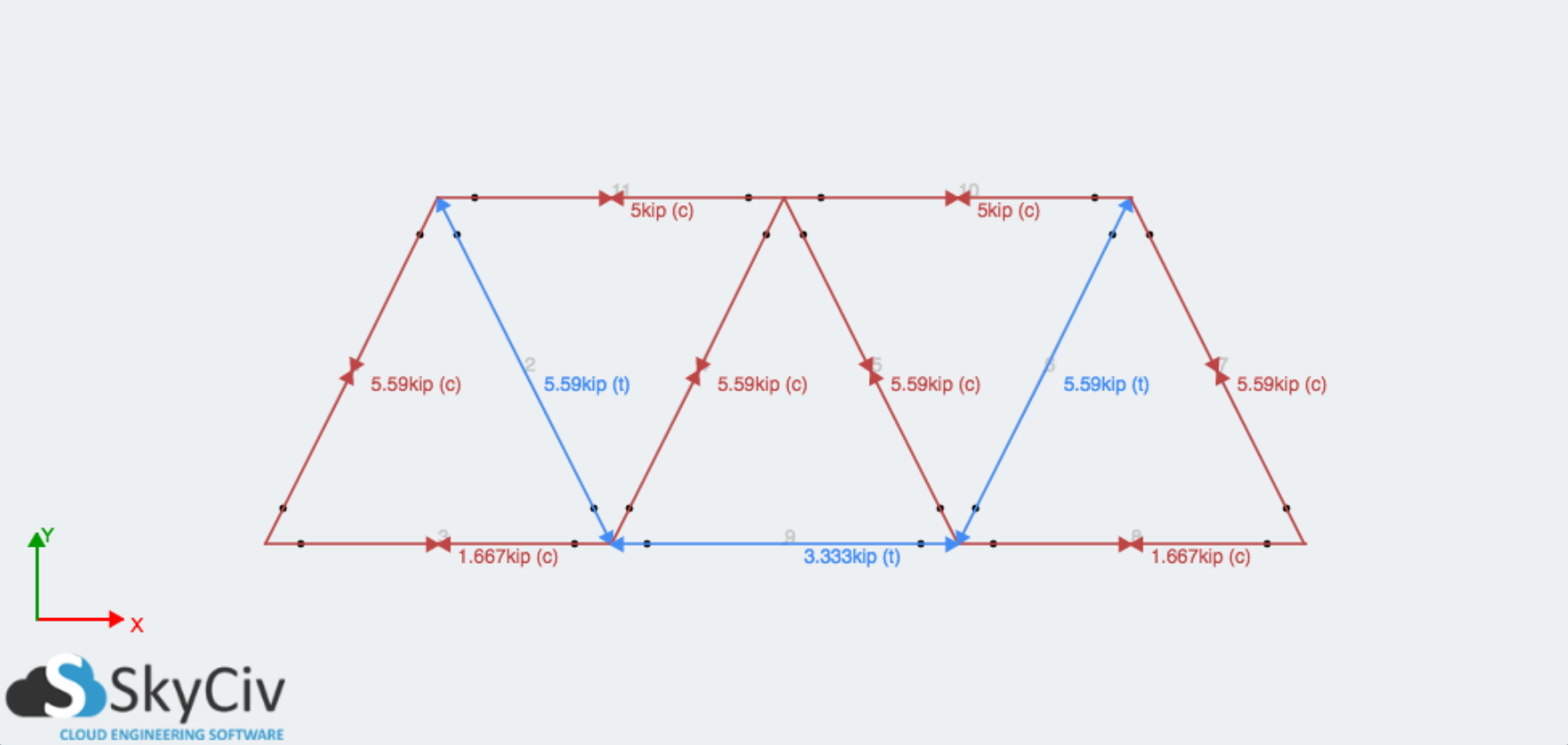
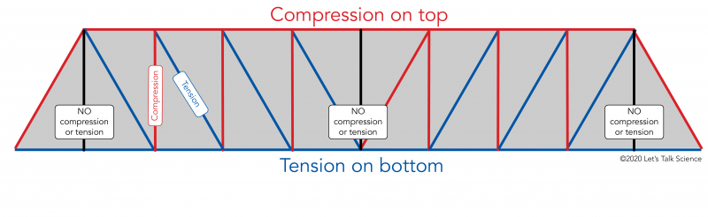
Truss bridge force diagram. Doing the Math: Analysis of Forces in a Truss Bridge - Notetaking Sheet. Notetaking Sheet . Free Body Diagrams . By definition, a free-body diagram is a representation of an object with all the forces that act on it. The external environment, as well as the forces that the object exerts on other objects, are omitted in a free-body diagram. Here are two diagrams showing how the forces are spread out when the Howe Truss is under a load. The first shows the load being applied across the entire top of the bridge. The second shows a localized load in the center of the bridge. In both cases the total load = 100. Therefore, you can take the numbers as a percentage of the total load. In this lesson, students learn the basics of the analysis of forces engineers perform at the truss joints to calculate the strength of a truss bridge. This method is known as the "method of joints." Finding the tensions and compressions using this method will be necessary to solve systems of linear equations where the size depends on the number of elements and nodes in the truss. The ... Description. Warren truss bridge with forces.svg. A diagram of a Warren truss bridge with forces and member stress colours (black for no stress, red is compression, blue is tension) Date. 2009. Source. My own work and calculations. Author.
Weiwei Lin, Teruhiko Yoda, in Bridge Engineering, 2017. 1.3.8.3 Truss Bridges. Truss is a structure of connected elements forming triangular units, and a bridge whose load-bearing superstructure is composed of a truss is a truss bridge. Truss bridges are one of the oldest types of modern bridges. In order to simplify the calculation, trusses are generally assumed as pinned connection between ... ARC 2213 BUIDLING STRUCTURE |FETTUCCINE TRUSS BRIDGE ANALYSYS REPORT 13 3.1.3 Force Distribution Figure 3.4: Force distribution diagram of Wadell A truss bridge The compression members of the trusses are shop- riveted built up sections, made of channels, angles, and plates, while most tension members are made of pairs of eye bars. The truss is a simple skeletal structure. In design theory, the individual members of a simple truss are only subject to tension (pulling) and compression (pushing) forces and not bending forces. This is the Washington Ave. Bridge in Waco, Texas. It is the longest and oldest single span truss still in continuous use in Texas. Cos θ = x / z. Sin θ = y / z. Tan θ = y / x. 2. Method of Sections for Truss Analysis. The section method is an effective method when the forces in all members of a truss are to be determined. If only a few member forces of a truss are needed, the quickest way to find these forces is by the method of sections.
The inputs will be the length and height of the bridge, the number of truss sections, and the amount of weight it needs to support. You will write a Matlab function that computes a matrix relating the net force on each joint to the tensile and compressive forces in the beams, and solve the resulting linear system to tell you how much tension or ... There are many types or subtypes of metal truss bridges, but only five were common in North Carolina — the Pratt, the Warren, the Parker, the Camelback and the Pennsylvania. Pratt truss diagram (source: HAER) The Pratt truss is identified by a simple web arrangement of diagonals in tension and verticals in compression. Patented in 1844 by ... Force distribution diagram of Wadell A truss bridge The compression members of the trusses are shop- riveted built up sections made of channels angles and plates while most tension members are made of pairs of eye bars. Model of the truss bridge with two traffic lanes. Here are two diagrams showing how the forces are spread out when the Pratt Truss is under a load. The first shows a localized load in the center of the bridge. The second shows the load being applied across the entire top of the bridge. In both cases the total load = 100. Please note that the force diagrams do not change if the load is applied ...
Cantilever Bridge Force Diagram - sankomat
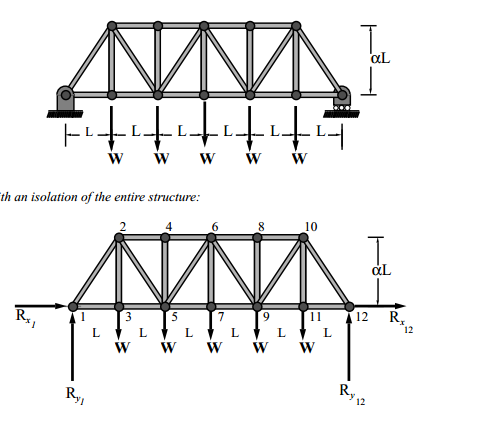
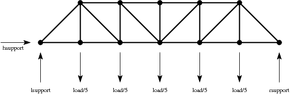
1. Draw a Free Body Diagram (FBD) of the entire truss cut loose from its supports and find the support reactions using the equations of equilibrium (we will see that for some truss structures this step is not always necessary); 2. Draw a FBD of a truss joint that has no more than two unknowns and use the two equations of equilibrium to find the two unknown truss member forces;

GN's GCE Portfolio: Triangular Bridge
Calculating Shear Force Diagram - Step 2: Keep moving across the beam, stopping at every load that acts on the beam. When you get to a load, add to the Shear Force Diagram by the amount of the force. In this case we have come to a negative 20kN force, so we will minus 20kN from the existing 10kN. i.e. 10kN - 20kN = -10kN.

Golden Gate Bridge at Dusk
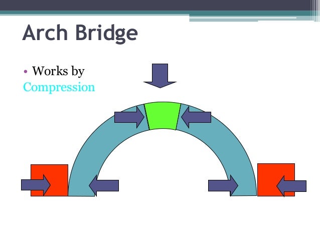
Bridges are of several types, some of which include beam bridges, arch bridges, cantilever bridges, suspension bridges, truss bridges, cable-stayed bridges, and tied arch bridges. Many bridges were built to last centuries. For instance, the Golden Gate Bridge in San Francisco, which was opened in 1937, took a total of four years to build and is one of the most famous bridges in the world.
About Us | Cloud Structural Software
Force diagram for a beam bridge. D. Daniela Morello. 6 followers . Bridge Engineering. Civil Engineering ... Forces, Arch Bridges, & Truss Bridges. Hands-on lesson on types of bridges, forces, and loads. Lessons are geared toward 4th and 5th grade children but can be used for elementary school and middle school aged children. Use these fun ...
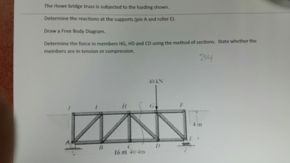
Solved: The Howe Bridge Truss Is Subjected To The Loading ...
Doing the Math: Analysis of Forces in a Truss Bridge - Annex 1 The forces on every node are illustrated above. The vertical forces acting on the upper nodes are denoted by F n, n being the node's number. Forces along the segments are denoted by Fnm, where nm denotes the force points from node n to node m. The reactions on the bridge ...

Monitoring of a bascule bridge during rehabilitation - IOS ...
n Explain the following structural engineering concepts: free body diagram, equilibrium, structural model, sym- metry, static determinacy, stability, and factor of safety. n Use the Method of Joints to calculate the internal force in every member in a truss.

New York.
Pratt Truss Bridge Introduction This example is inspired by a classic bridge type called a Pratt truss bridge. You can identify a Pratt truss by its diagonal members, which (except for the very end ones) all slant down and in toward the center of the span. All the diagonal members are subject to tension forces only, while the shorter vertical ...

Define Beam Truss Bridge - The Best Picture Of Beam
Calculate the reactions at the supports of Frame and Truss - statically determinate and statically indeterminate, automatically calculate bending moment and shear force of Frame and Truss

Charlotte Walsh's Honors Physics Blog: February 2014
Interestingly, as a load (such as a car or train) moves across the bridge sometimes the forces for a member switch from compression to tension. This happens especially to the members near the center of the bridge. How the forces are spread out. Here are two diagrams showing how the forces are spread out when the warren truss is under a load.

Tutorial for Truss Method of Joints | SkyCiv
Here are two diagrams showing how the forces are spread out when the K Truss is under a load. The first shows the load being applied across the entire top of the bridge. The second shows a localized load in the center of the bridge. In both cases the total load = 100. Therefore, you can take the numbers as a percentage of the total load. The K ...

Bridgeport Bridge State Street Bridge Historicbridges ...
Therefore, the forces that a truss absorbs are the weight (equal to mass multiplied by gravity) of its members and additional outside forces, such as a car or person passing over a bridge. In the diagram of the simple truss, the forces are represented by black arrows in units of Newtons.
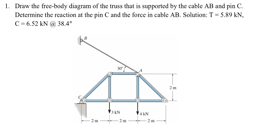
Solved: Draw The Free-body Diagram Of The Truss That Is Su ...
This free online roof truss calculator is a truss design tool that generates the axial forces, reactions of completely customisable 2D truss structures or rafters. It has a wide range of applications including being used as a wood truss calculator, roof truss calculator, roof rafter calculator, scissor truss calculator or roof framing.
Suspension Bridge - How Bridges Work
The major components of a typical truss bridge are illustrated in the two diagrams below. The elevation view shows the bridge from the side. The isometric view is a three-dimensional representation of the structure. Note that certain members are only visible in the isometric view. 1-2 A typical truss bridge.
Bridges - Building Structures - Gr.3 Science
This instructable will go over how to correctly analyze a truss bridge using the method of joints. This technique is common in civil engineering practice. The purpose of this analysis is to take into account the structure, supports, and loads, and calculate the forces within each member of the truss.
Trusses - Structural Analysis (Aero 103)

Warren Truss - Garrett's Bridges: Resources to Help You ...
Solved: Draw The Free Body Diagram Of The Truss Structure ...
How to calculate tension/compression in a truss bridge ...

Block Research Group
What is a Truss? | SkyCiv
Solved: 1) Draw The Free-body Diagram For The Supporting S ...

For the Pratt bridge truss and loading shown, determine ...

Welders Universe - Steel Framing and Construction Tutorial

Britannica does not currently have an article on this ...

truss bridges - Google Search | Truss bridge, Bridge ...

K-truss 2 | Bridge, Bending moment, In this moment

Pratt Truss Dimension. | Download Scientific Diagram

Everything was looking particularly lush in the rain whilst heading up to Colwith Force.
[Solved] The Howe bridge truss is subjected to the loading ...
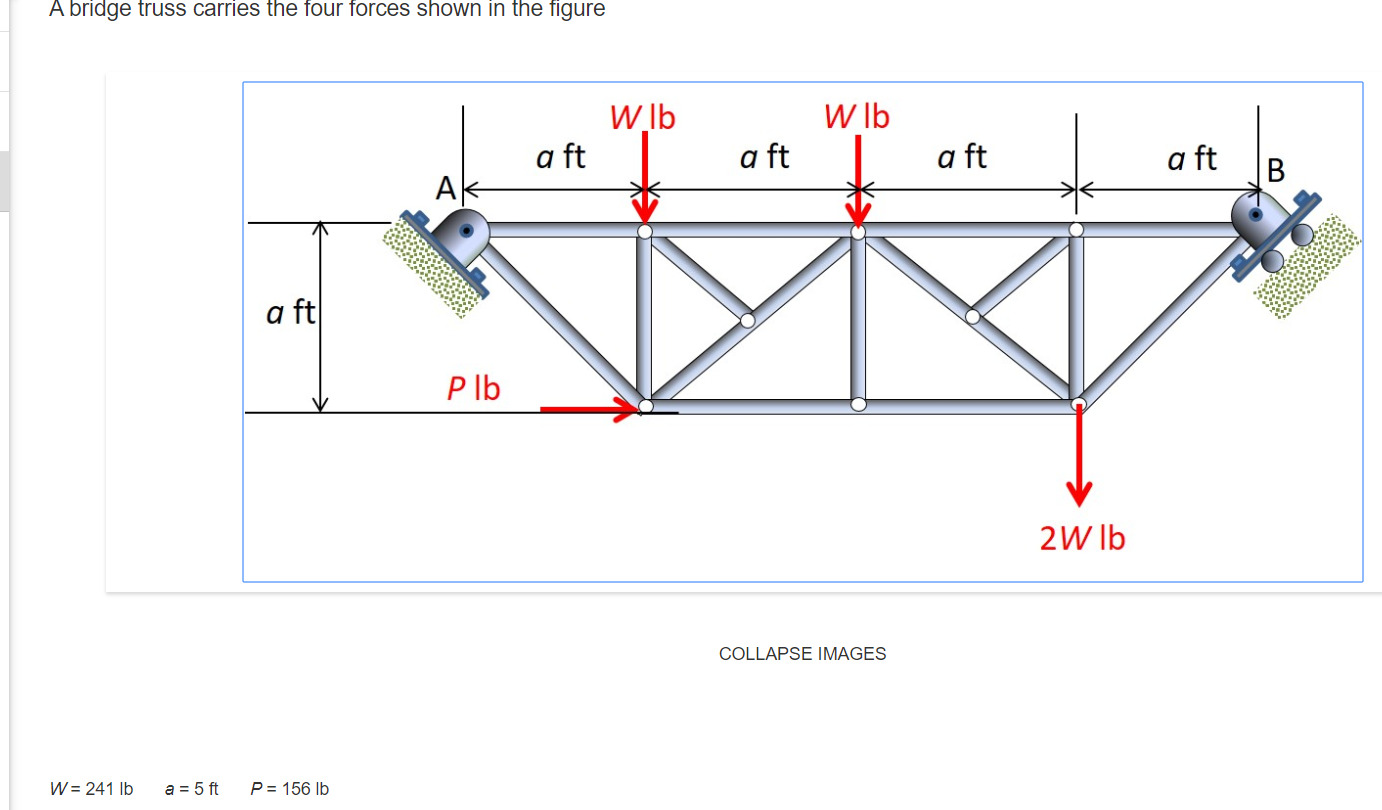
Solved: A Bridge Truss Carries The Four Forces Shown In Th ...

Statics eBook: 2-D Trusses: Method of Joints
3D Analysis Of Truss Bridges
Second River Niger Bridge And A Sea Port At Onitsha: Shall ...
and consider the force diagram for J5:
Rail Bridges
Why is a Triangle a Strong Shape? | Let's Talk Science

Bridges by David Blockley

Bildergebnis für truss bridge designs paper | Truss bridge ...
Comments
Post a Comment