43 block diagram digital logic
Hello I am Pushpa, I have completed my Bachelor's degree in Electronics and Communication Engineering (ECE) with distinction and also got 99.7% in GATE 2019. I am a dedicated freelancer and I can help in online assignments. For help please contact me through below email address: pushparathod312@gmail.com My strong subjects are listed below. 1. **Electrical Circuit Theory/ Electrical Networks:** Topics: KCL,KVL,star-delta,delta-star,Network Theorems(superposition,thevenins,nortons,maximum po... These kinds of applications re- quire the use of electronics modules (pre-amplifiers, amplifiers & discriminators, external delay and TACs - time- to-amplitude ...
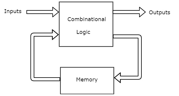
22 Jun 2019 — Control signals are mostly 1 bit of data, a single boolean. These typically enable or disable some output, telling a Mux to select between one ...
Block diagram digital logic
[This](https://i.imgur.com/C0QEkSw.jpg) is part of an IC's block diagram. (I've stripped out what wasn't relevant for ease of parsing.) This IC generates a digital ground at the TEST pin that is 5V below the V+ pin. The external system ground is at V-. So if V+ was 9V, then V- = 0V, and TEST = 4V, giving you your 5V between TEST and V+. An external LCD uses that internally generated 5V range, and you can also use it with some 5V logic gates in order to level shift everything where the LCD n... Hello entrepreneurs, I am the founder of [WeLoveNoCode](https://welovenocode.com/). We help entrepreneurs and businesses build MVPs, websites, apps with no-code technology. With this in mind, I thought to share about a few you can check out if you want to get an MVP up in a week. I hope you find this useful. I'm open to answering questions regarding the no-code industry. # Ideation tools. 1. **Miro** is a visual collaboration no-code platform that provides you with a whiteboard canvas. You ca... This semester I took Digital Systems II where we used Quartus and coded with Verilog HDL. Since it was an online class because of covid it wasn't until four weeks into the semester where we had to do labs in the university. I did learn that it is like making a digital circuit, or at least that is how what I learned from it. Since we would get a block diagram with inputs and outputs and we had to do the logic and then test it in the simulation waveforms. I keep looking online for real-world a...
Block diagram digital logic. Functional Blocks. Lecturer: Dr. Annie Guo. S2, 2008. COMP9032. 2. Logic Gates. • Virtually all problems can be solved by digital circuits and systems.6 pages Block diagrams are a method of explaining complex systems (not necessarily electronic) in a simple manner. They are made up from labeled blocks which are joined ... The Function Block Diagram (FBD) is a graphical language for programmable logic controller design, that can describe the function between input variables ... So firstly, I know one of the 3rd party math libraries already has a function for this -- I'm thinking of doing it purely for the educational value, not for the value of the program itself. Secondly, I'm very new to Python, but only kind of new to programming. My first experience with programming was using Matlab for lab assignments in a linear algebra class a couple years ago, then I had a digital logic design course, which, while it didn't teach me programming, did teach me how to build up...
I was going to call this an "informal guide to skipping class" but I thought people might get the wrong idea. Tandon's CS program, unlike CAS and the majority of other school's with CS programs, does not have any sort of CS placement. Officially, the only course an incoming CS/CE/ECE major can skip is the very first Intro course with an AP CS exam score of 4 or 5. Unofficially, you can skip all of the requirements of any of the majors so long as you get enough credits in the required course wor... Wooster Ashely was a low level-bureaucrat who couldn't remember the last time they had their clock speed lower than 2.55:1. Low-level, on paper anyway. In reality, if need be he could command a large section of the TGC military and all of the malware lying in wait seeded throughout Union space just in case. *We're at 80 heavy patrol ships, another 20 being built. Seven medium patrol ships, another three being built. The light patrol ship... thank god I'm not in charge of coordinating that projec... I'm a physics graduate student looking to gain experience and knowledge with FPGAs. I was wondering what people's work flows are with FPGAs, as a beginner and as industry professionals. I have familiarity/am comfortable with digital logic, how FPGAs work, and what they're used for. Also have 3-4 years of experience programming in Python/C/C++/Javascript I have no coursework in FPGAs or Electrical Engineering. All I've learned about FPGAs, I found online on channels/websites like nandland and a... The logic diagram consists of gates and symbols that can directly replace an expression in Boolean arithmetic. A logic gate is a device that can perform one ...
The New York Times recently published two great articles about syn bio. One is about Drew Endy, the other is about DNA synthesis. I think these are two of the best articles I've read about syn bio addressed to a mainstream audience. Share with friends, family, anyone who cares about the future of our planet and species. Thanks to biotech I can see my family over the holidays without worrying about killing them. What a world. Well done Dr. Endy! [The Gene Synthesis Revolution](https://www.nytime... The goal here was to create a basic, low-power pc for email, facebook, and occasional casual games. It's overkill for that purpose, I think. But I wanted to build a Ryzen system, my past builds were all Intel. Look at this non-cable managed trash. It's hideous. https://i.imgur.com/QWkAMvW.png https://i.imgur.com/kpTk1bM.png Unfortunately, the non-modular PSU means the CPU power cable barely reaches, so no choice but to stretch across the entire board. Ditto the USB connector which has to r... Hi Everyone, happy 2021 and good riddance to 2020! We (the moderation team) are working on updating the wiki with better guides and resources. With that in mind, I've put together the wiki in this thread, and would like your help in improving it. **Please post any robotics questions you have, and any recommended resources, in the comments. They can be career, educational, technical, beginner or expert.** I'll be updating this post based on the comments, so it's a work in progress. #How to get... Sep 22, 2021 · As illustrated in the block diagram, an analog signal may always be transformed into a digital signal by combining three fundamental operations: sampling, quantizing and encoding. Only sample values of the analog signal at regularly spaced discrete-time instants are maintained during the sampling procedure.
Plc Programmable Logic Control Block Diagram Input Output Modules D E Notes
I/O gets present after present instead of well deserved lumps of coal (which the poor bastard would also just love) and Pantsu continues applying scaly taloned foot to cybrenetic ass. [First](https://www.reddit.com/r/HFY/comments/oa5a21/the_great_erectus_and_faun_chapter_one_faun_makes/) [Previous](https://www.reddit.com/r/HFY/comments/q51xy3/the_great_erectus_and_faun_the_saga_of_blarg_the/) \*** In the near perfect void around I/O, a star popped into being. It was a small, dim thing, normal...
1
Sep 16, 2015 · Block-diagram style digital logic visualizer. Contribute to ducky64/chisualizer development by creating an account on GitHub.

Block Diagram Of The Waveform Printed Circuit Board The Digital Download Scientific Diagram
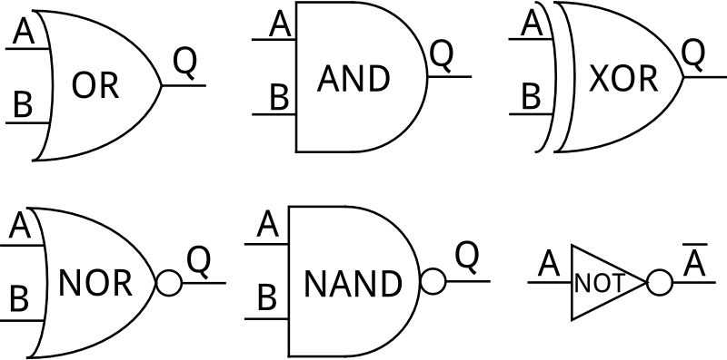
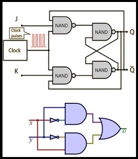
In the standard from IEC, a lot of function blocks are described. Here’s an overview of the most important blocks in the official FBD description. The most basic functionality of a PLC program is logic. Combined called combinatorial logic. Logic is the simplest form of algorithm that, via the states of its inputs can set some outputs. Basically, there are two different bit logic functions or operations in FBD. With just these two you can derive a whole bunch of other logic functions. But let’s start with the first one: At first I would like to introduce you to the OR function block. It takes 2 inputs and has 1 output, and works just like an OR gate. In FBD the block will typically look like this: As you probably have seen the symbol for an OR operation is >=1. It is basically the condition for the output. If the sum of the two inputs are greater than or equal to 1, the output becomes true. Just like with all the other bit logic operations false is represented by a 0 and true by a 1....
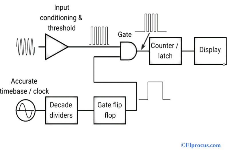
Frequency Counter Block Diagram Circuit Types And Its Applications
Visual Paradigm's logic diagram tool features a handy diagram editor that allows you to draw logic diagrams swiftly. The logic gate software has all the logic symbols you need to design any kind of logic model. No matter you want a logic diagram tool for teaching, or a logic circuit software for engineering purposes, our online logic diagram creator just works perfectly. Besides the logic diagram tool, we've put together some logic diagram templates to help you get started.

Pxie 6570 6571 Block Diagrams Digital Pattern Help National Instruments
Ministry of Defence of the Russian Federation Министерство обороны Российской Федерации   **Russian Examination of the F-35**   Minutes after a lone F-35, flown by Mr. Viljo Kukkamäki (RIP), showed up in Russian airspace, teams from a large consortium of Russian defense entities - including Almaz-Antey, Tikhomirov NIIP, NIIR Phazotron, United Aircraft Corporation, Leninetz and Radiofizika - had already begun preparations for study of the American aircraft. The informati...

What Is Digital Voltmeter How It Works Types Applications Advantages
My house is neither old nor gothic, and at face value, there is absolutely nothing creepy about it. It sits on an expansive lot just far enough from town to feel pleasantly rural. The walls inside range from a crisp, clean white in the living room and breakfast nook to a cheery buttercup yellow in the hallways, kitchen, and office. The larger bedroom is a sweet lavender, while the smaller is the kind of little-boy blue that would’ve given away instantly that it had belonged to the former owner’s...

Block Diagram Of An Aer Ca Digital Logic Of Each Cell In The Grid For A Download Scientific Diagram
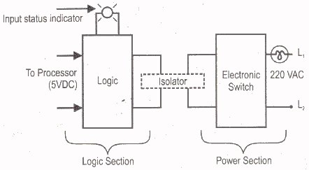
Key among the utility boards is the Power block. Each Logic gate requires power to operate, and this board is there to supply it. The Power block has a single, female, input header, and should be plugged into the output of the last logic gate. You'll only need ONE power block to supply power to an entire digital logic circuit.
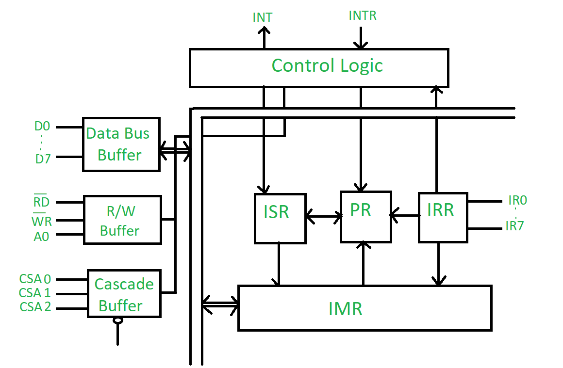
Block Diagram Of 8259 Microprocessor Geeksforgeeks
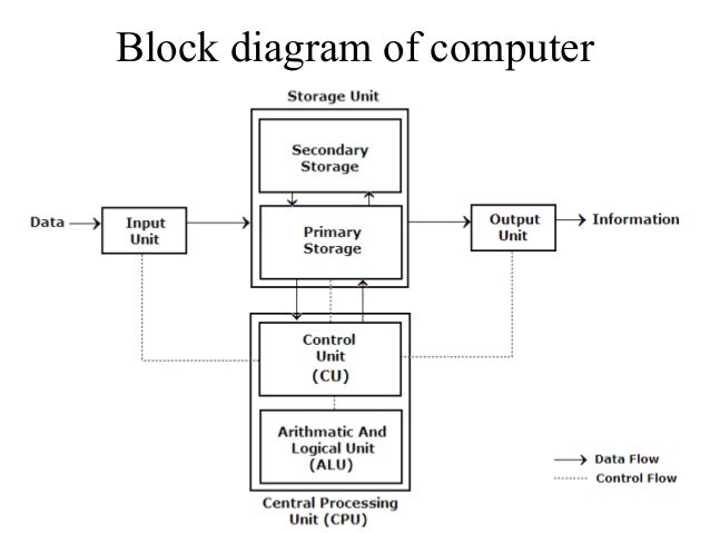
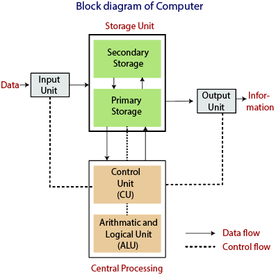
Block Diagram of Digital computer A digital computer is considered to be a calculating device that can perform arithmetic operations at enormous speed. It is defined as a device that operates upon information/data. To be able to process data the computer is made of various functional units to perform its specified task. Input Unit:
A Simple Arithmetic And Logic Unit
This is the final part, out of 3, for a massive theory that aimed to clarify the seemingly contradictory lore about Gellar Fields. [Part 1:](https://www.reddit.com/r/40kLore/comments/ktastm/an_analysis_of_the_metaphysical_mechanisms_behind/?utm_source=share&utm_medium=web2x&context=3) [Part 2:](https://www.reddit.com/r/40kLore/comments/ktbp2b/an_analysis_of_the_metaphysical_mechanisms_behind/) For those of you that have managed to make it this far, here's a virtual high five from acr...

Learning Sequential Logic Design For A Digital Clock 14 Steps Instructables
So I'm currently in digital logic 2. In the first class I worked with karnaugh maps, and feel somewhat comfortable using them for up to 4 variables, and don't cares. For prelab work due in a couple days, I have to design a logic diagram and convert the diagram to a chip layout for a given characteristic table. Again, this is something I'm normally comfortable with. However, this time I have to simplify a 3 variable characteristic equation that describes a sequential circuit, given as a table. A...

Function Block Diagram Wikipedia
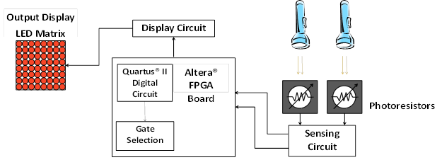
This semester I took Digital Systems II where we used Quartus and coded with Verilog HDL. Since it was an online class because of covid it wasn't until four weeks into the semester where we had to do labs in the university. I did learn that it is like making a digital circuit, or at least that is how what I learned from it. Since we would get a block diagram with inputs and outputs and we had to do the logic and then test it in the simulation waveforms. I keep looking online for real-world a...
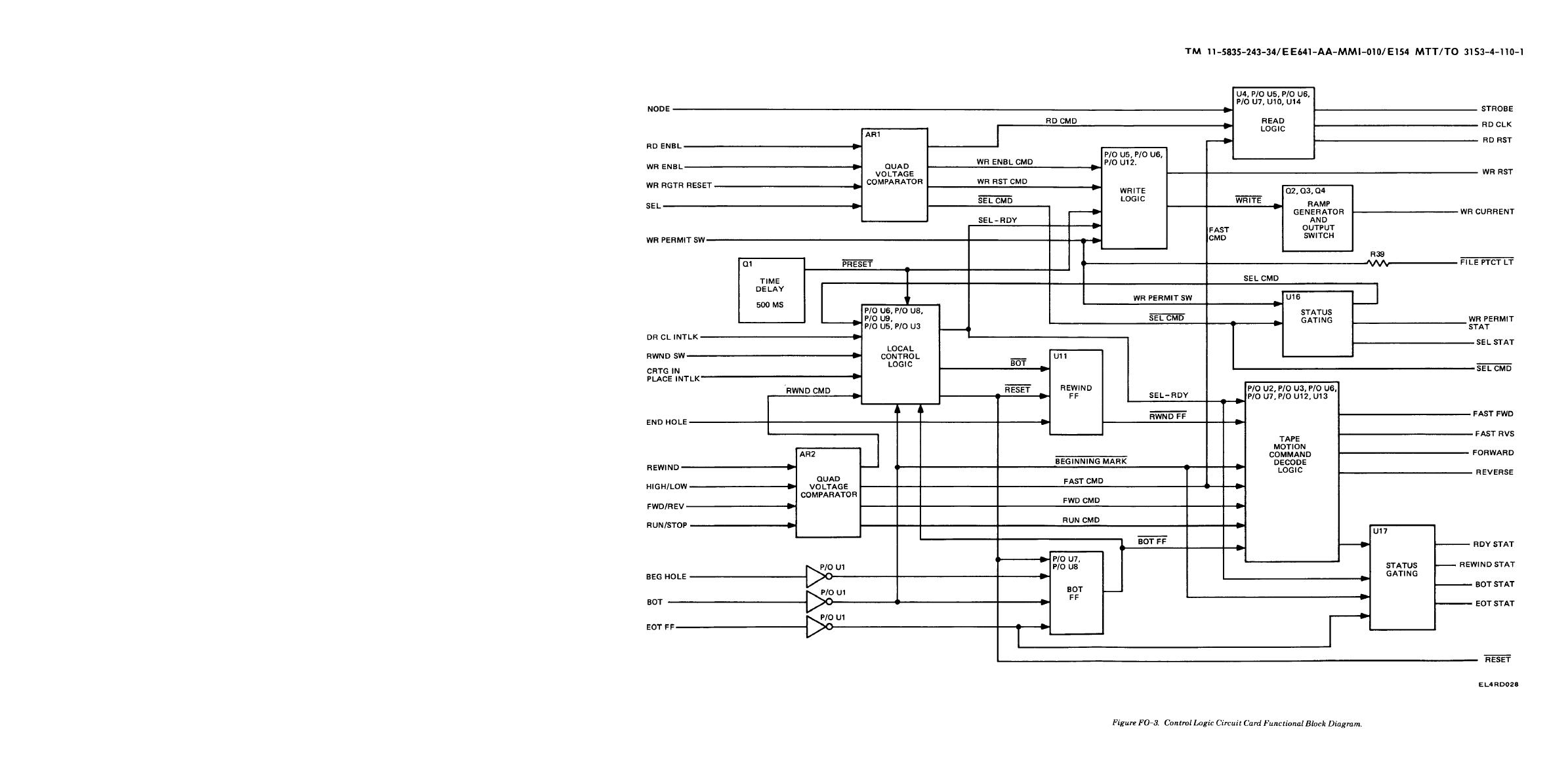
Figure Fo 3 Control Logic Circuit Card Functional Block Diagram
Hello entrepreneurs, I am the founder of [WeLoveNoCode](https://welovenocode.com/). We help entrepreneurs and businesses build MVPs, websites, apps with no-code technology. With this in mind, I thought to share about a few you can check out if you want to get an MVP up in a week. I hope you find this useful. I'm open to answering questions regarding the no-code industry. # Ideation tools. 1. **Miro** is a visual collaboration no-code platform that provides you with a whiteboard canvas. You ca...

Digital Design Combinational Logic Design Chapter 2 Combinational
[This](https://i.imgur.com/C0QEkSw.jpg) is part of an IC's block diagram. (I've stripped out what wasn't relevant for ease of parsing.) This IC generates a digital ground at the TEST pin that is 5V below the V+ pin. The external system ground is at V-. So if V+ was 9V, then V- = 0V, and TEST = 4V, giving you your 5V between TEST and V+. An external LCD uses that internally generated 5V range, and you can also use it with some 5V logic gates in order to level shift everything where the LCD n...
00nb929 Wls929 433 Pwls929 433 Wireless Key Block Diagram Digital Security Controls
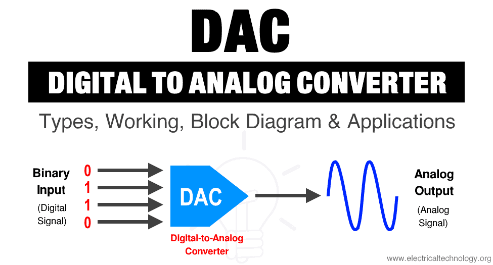
Digital To Analog Converter Dac Types Working Applications

Logic Analyzer Vs Oscilloscope Saleae Articles

Functional Block Diagram Wikipedia

Logic Block Diagram For Dm And Wgm Time To Digital Converter And Download Scientific Diagram
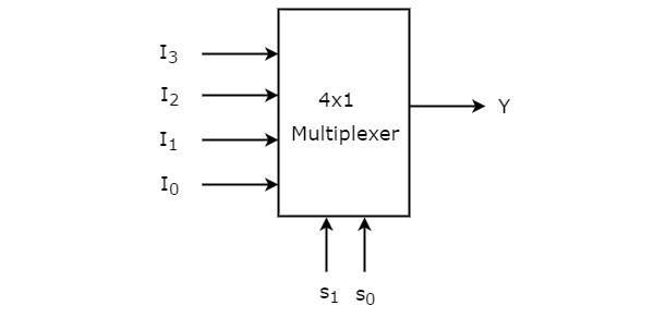
Digital Circuits Multiplexers
Basic Digital Logic Gates Emulator A Learning Tool For Kids And Adults
Digital Circuits Finite State Machines

Ecen 2350 Digital Logic Rebecca Hoffmann
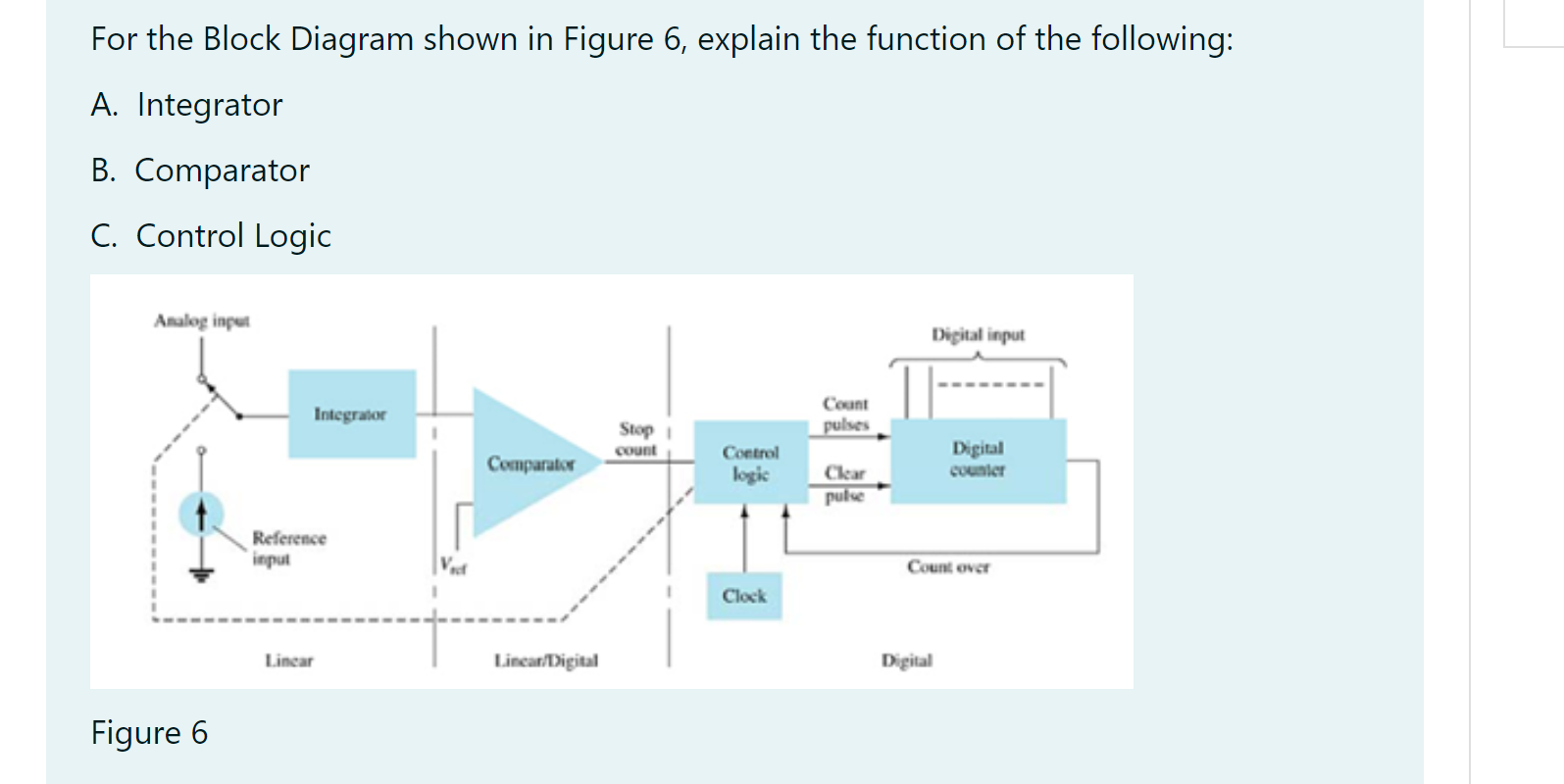
Solved For The Block Diagram Shown In Figure 6 Explain The Chegg Com
3

Block Diagram Matlab Simulink

Fpga Logic Design Block Diagram Download Scientific Diagram
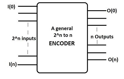
Encoder Digital Wikipedia
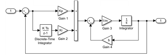
Simulink Models Matlab Simulink
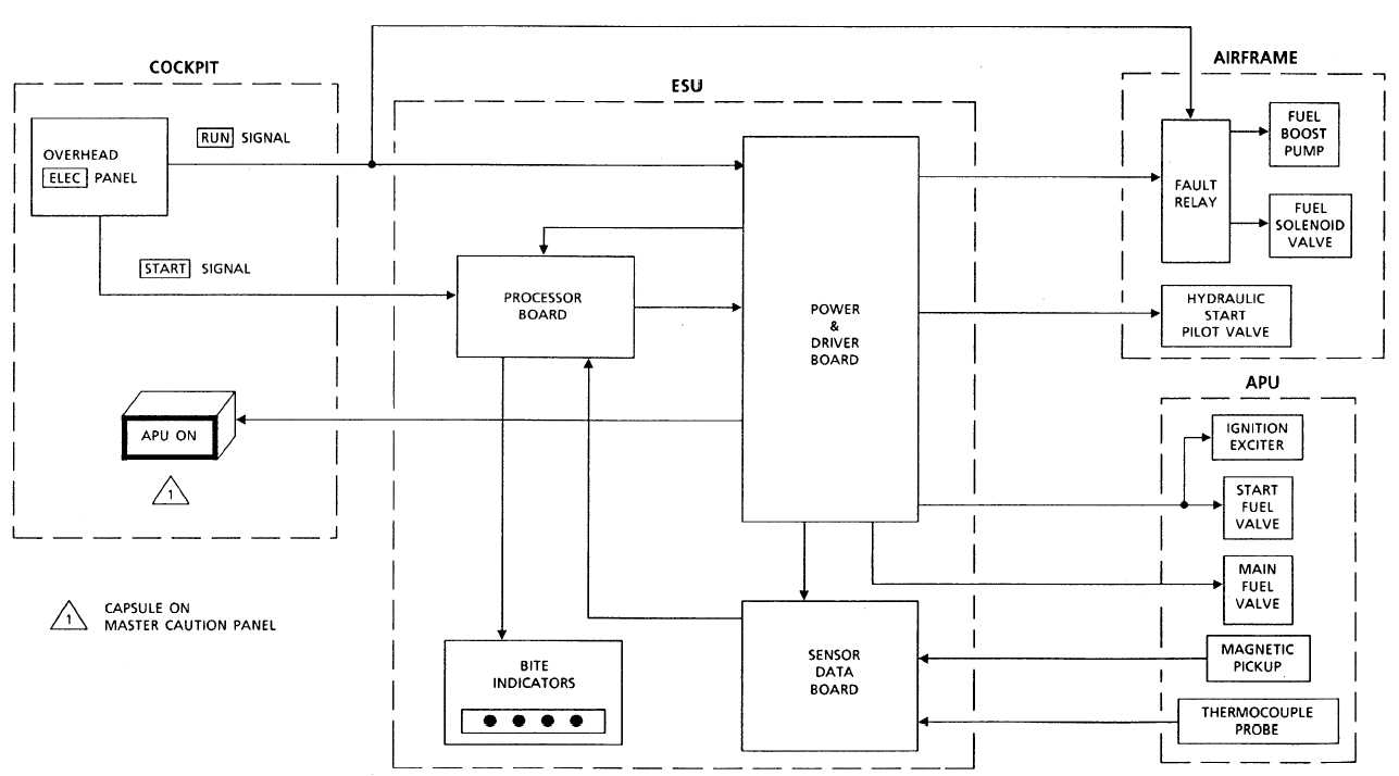
Esu Block Diagram

What Is Digital Signal Processing Dsp A Complete Overview

Digital Multimeter Block Diagram Explanation Electronics And Communication Study Materials
Logicblocks Digital Logic Introduction Learn Sparkfun Com

Computer Science Meterial Define Computer Explain Block Diagram Of Computer
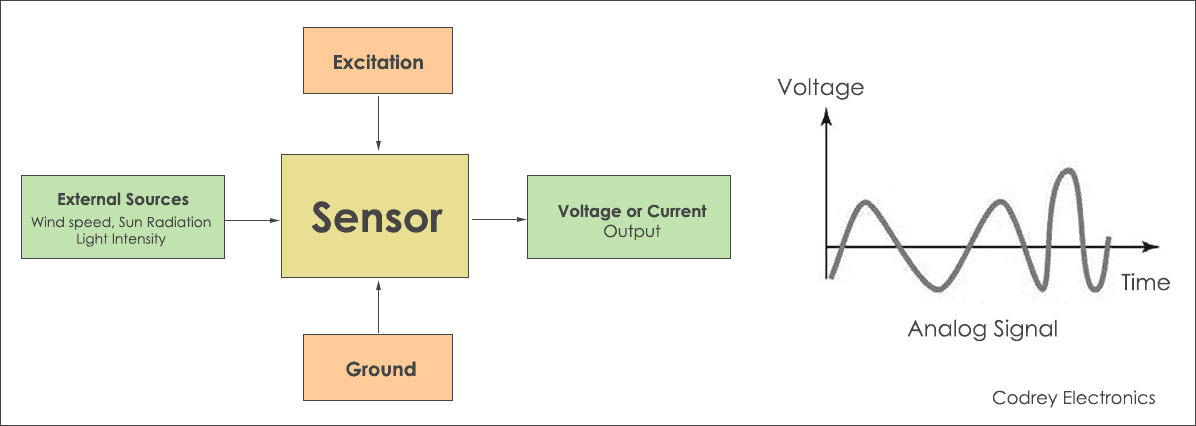
Different Types Of Sensors Analog And Digital Codrey Electronics
1

Block Diagram Of Programmable Logic Array

A Rapid Prototyping Environment For Teaching Digital Logic Design
Digital Logic Notes Block Diagram Of Computer Number System And Complements
Digital Logic Design Narrative 1 A Data Coder Decoder System Block Diagram Is Given Below We Have 3 Bitt Information To Be Coded And Transmitted Course Hero
What Are The Different Types Of Digital Logic Circuits With Working

Block Diagram Wikipedia
Block Diagram Of Computer Tutorial And Example

Analogue To Digital Conversion Tutorial Circuits Sequential Logic Electronic Hobby Projects
Comments
Post a Comment