41 visio context diagram
Click the File tab. · Click New, click Software and Database, and then double-click Data Flow Diagram. · From the Data Flow Diagram Shapes stencil, drag an ... Visio bruker vektorgrafikk for å lage diagrammer og leveres med sett av former, sjablonger og maler. ... Visio, kan du enkelt lage diagrammer som ...
How to create the Visio diagram from ... how to create system context diagram in visio ... Which version of Visio creates MUTCD traffic diagrams?
Visio context diagram
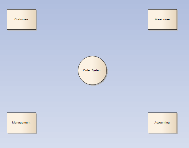
Diagram Wiring Honeywell 7500 Thermostat No Heat Wiring Diagram 1966 Pontiac Wiring Diagrams , Microsoft Visio Context Diagram , Wiring Diagram For ... Draw Context Diagram Using Visio Written By Dominquez Busell Tuesday, November 16, 2021 Add Comment Edit. 1. How to Create a Block Diagram in Visio . Block diagrams play several significant roles. They can be of great assistance whenever a clear image of a system or control flow is needed. These blocks illustrations make it easier for software ... To create new DFD, select Diagram > New from the toolbar. In the New Diagram window, select Data Flow Diagram and click Next. Enter Context as diagram name and click OK to confirm. We'll now draw the first process. From the Diagram Toolbar, drag Process onto the diagram. Name the new process System.
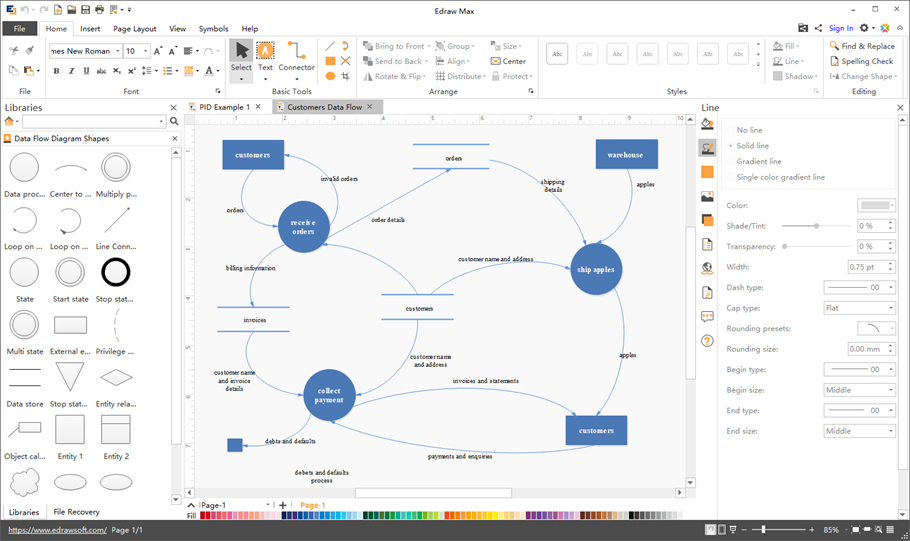
Visio context diagram. Let's draw a context DFD. To create a DFD, select Diagram > New from the toolbar. In the New Diagram window, select Data Flow Diagram and click Next. Enter Context Diagram as diagram name and click OK to confirm. Name the diagram Context Diagram. We need to create the main process. Drag Process from diagram toolbar to diagram. A context diagram, as a level 0 data-flow diagram, is a visual representation that defines the boundary between the system and external entities. Due to the complexity of context diagram, it is always advised to use such context diagram software that comes with massive symbols and relative elements. Is there an affordable software to create Visio data flow diagram on Mac? Try Edraw Max. It will help you create professional data flow ... This template shows the Context Diagram. It was created in ConceptDraw DIAGRAM diagramming and vector drawing software using the Block Diagrams Solution from the "Diagrams" area of ConceptDraw Solution Park. The context diagram graphically identifies the system. external factors, and relations between them. It's a high level view of the system.
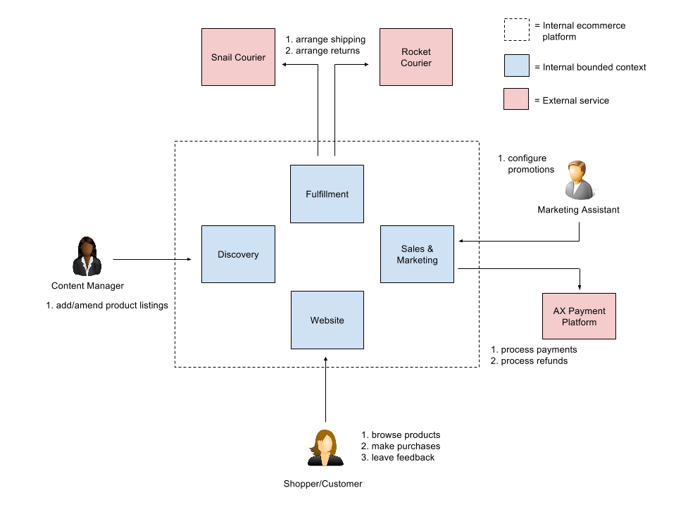
... Diagrams in Visio automatically in a Visio template ... Using Microsoft Visio, you can create IDEF0 context diagrams for your products and projects. Visio Network Diagram Templates Download: Visio templates are the graphical and diagrammatical representation of a product, a project or an event. These templates make the work easy by eliminating lots of data and instead of the data we take diagrams and graphical representation. This also helps in understanding the project or event easily. Many FMC shapes have specific actions and options available in the context menu. ... their Request-Response symbol by unselecting it in the context ... System Context Diagram. I believe it's vital to give people a high-level overview of the system — the users, the use-cases, the major internal systems, and essentially those risky external ...
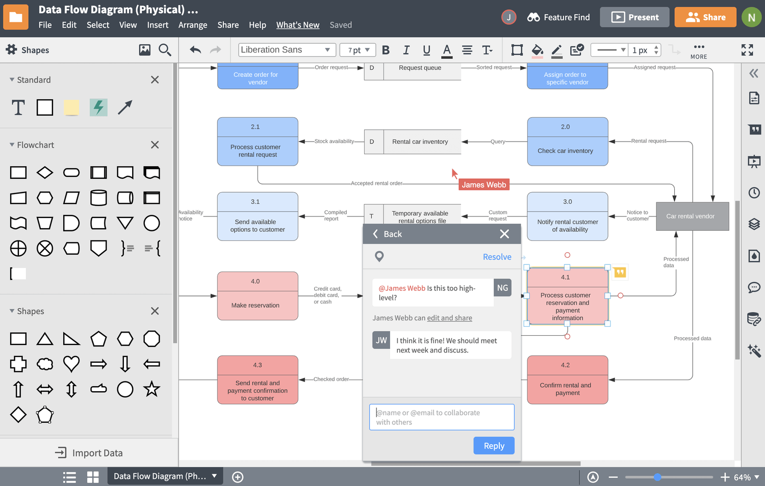
The System Context Diagram tool allows you to visualize the relationships among system objects easily and quickly. It comes with a System Context Diagram editor that is concise and intuitive, designers will not be disturbed by the cumbersome popups and messages. Instead of a blank wireframe, you may start with a System Context Diagram template ... Select Software and database as the drawing type and click on Data Flow Model Diagram and then click on the create button (look for this on the right side). Using Microsoft Visio, you can create IDEF0 context diagrams for your products and projects. These diagrams are a form of flowchart, detailing the appropriate course of action for a particular circumstance. Building these diagrams in Visio is fairly simple, consisting mostly of drag-and-drop operations. Data Flow Diagram Levels. Context Diagram. A context diagram is a top level (also known as "Level 0") data flow diagram. It only contains one process node ("Process 0") that generalizes the function of the entire system in relationship to external entities. DFD Layers. Draw data flow diagrams can be made in several nested layers.
Use Ms Visio Or Lucidchart To Create The Context Chegg Com
A context diagram, also known as a system context diagram or level-0 DFD, communicates a high-level overview of the flow of data within a technical system. With virtually no technical knowledge required to understand this type of system diagram, engineers, analysts, developers, and stakeholders can easily use it as a visual reference for ...
Creating An Dfd Using Microsoft Visio
Add a script editor webpart on the page and copy-paste the following code. After that, all you need is the URL of a Visio diagram that you want to work with. Just upload the Visio diagram to SharePoint Online and open it in Visio on the web. From there, open the Embed dialog and use the Embed URL in the above example.
Create Simple And Complex Diagram In Microsoft Visio By Rabia49 Fiverr
Hi, How can i create a system context diagrams in Visio 2007?
Context Diagram Wiki Bawiki
วาด context diagram ด้วย microsoft visio
Domain Driven Architecture Diagrams By Nick Tune Strategy Architecture Continuous Delivery And Ddd Medium
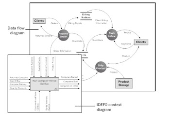
The context diagrams are widely used in software engineering and systems engineering for designing the systems that process the information. IDEF0 Visio ConceptDraw PRO extended with IDEF0 Diagrams solution from the Software Development area of ConceptDraw Solution Park is a powerful diagramming and vector drawing IDEF0 software.

Data Flow Diagram Dfd For A Purchasing Website Notes Emeroo Some Techtips
Visio is a diagraming tool that makes it easy and intuitive to create flowcharts, diagrams, org charts, floor plans, engineering designs, and more, using modern templates with the familiar Office experience. On this page, you can access some of the top templates and sample diagrams available in Visio, or request ones that you want. To see the hundreds of templates and sample diagrams available ...
How To Draw Use Case Diagram In Word Visio Online
Yes, UML stencils are availible in Professional and Premium editions. Visio 2010 Edition Comparison. 3rd-party add-ons are available that ...
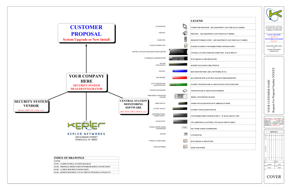
Visio Generic Security System Network Diagram
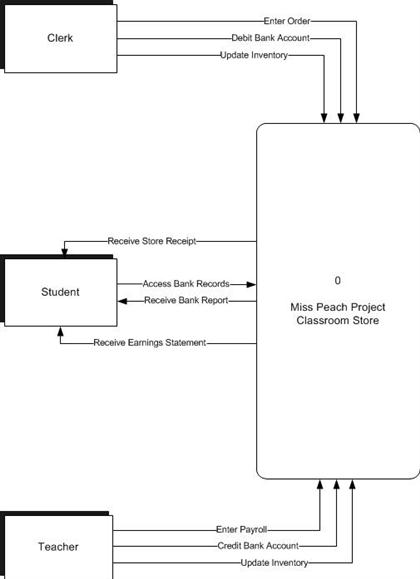
The system context diagram (also known as a level 0 DFD) is the highest level in a data flow diagram and contains only one process, representing the entire system, which establishes the context and boundaries of the system to be modeled. It identifies the flows of information between the system and external entities (i.e. actors). …
Chapter 9 Creating Flowcharts Microsoft Office Visio 2003 Inside Out Inside Out Microsoft
About Press Copyright Contact us Creators Advertise Developers Terms Privacy Policy & Safety How YouTube works Test new features Press Copyright Contact us Creators ...
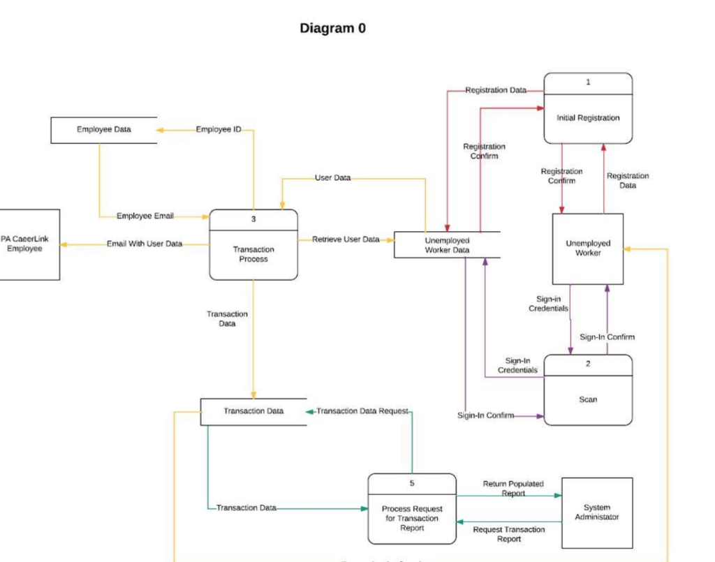
1
Use Creately's easy online diagram editor to edit this diagram, collaborate with others and export results to multiple image formats. You can edit this template and create your own diagram. Creately diagrams can be exported and added to Word, PPT (powerpoint), Excel, Visio or any other document.
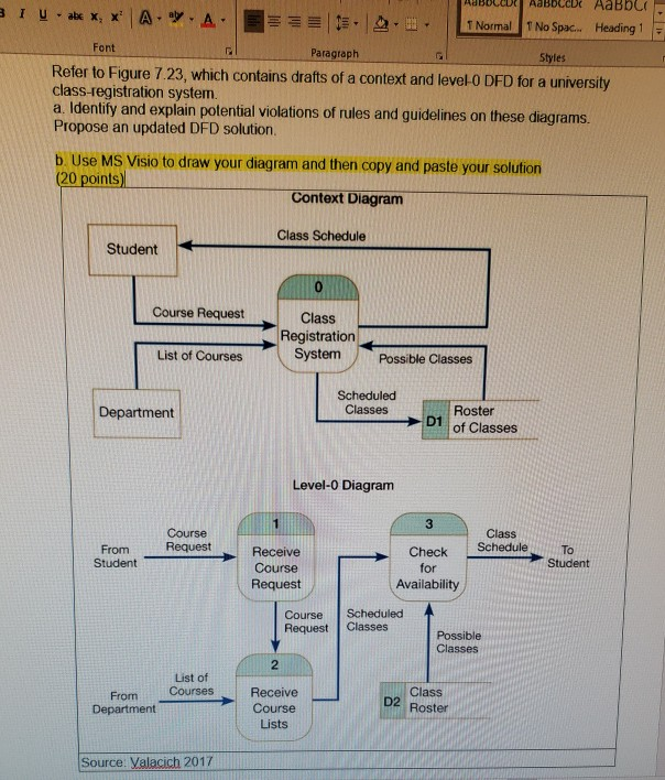
Solved T Normal No Spac Heading 1 Font Paragraph Es Refer Chegg Com
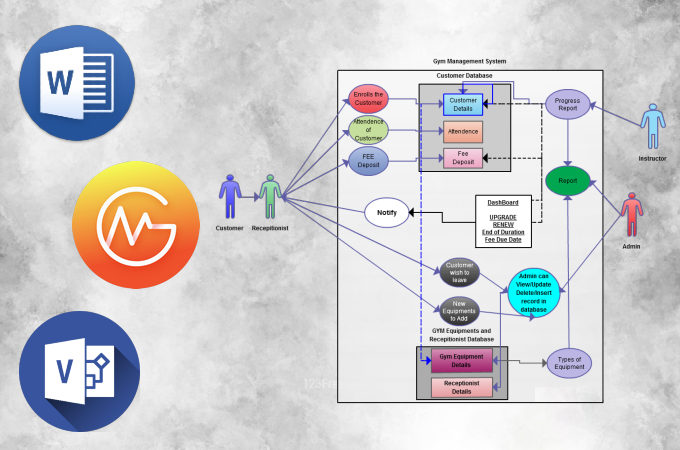
A context diagram is a visual representation of the relationship between data and business processes. This diagram has 3 main components which include external entities, system processes, and data flows. It provides the factors and events you need to consider when developing a system. With it, you will be able to determine the scope, boundaries ...
Create A Gane Sarson Data Flow Model Diagram
Once the diagram is more concrete, it may become an artifact using Visio or some other tool which supports context diagrams: 1: Using a white board or other flexible writing tool, draw a context diagram for the highest level process at hand (known as level 0).

Uml Class Diagram In 10 Steps Using Microsoft Visio 2010
Context diagram—The topmost diagram in an IDEF0 model. Parent/child diagram—An IDEF0 decomposition hierarchy using parent/child relationships. Node trees—Tree-like structures of nodes rooted at a chosen node and used to represent a full IDEF0 decomposition in a single diagram. Create a context diagram. Open Visio.

Flow Diagram Clipart Clipart Suggest
Visio web app. Included with Visio Plan 1 and Visio Plan 2. Extend your Microsoft Visio experience to the browser, where you can view, create, and edit diagrams stored in the cloud. Allow Microsoft 365 subscribers to view, print, and share diagrams and insert comments on the go. Visio for the web is always up to date.

Creating An Information System Data Flow Diagram Information Security University Of Florida
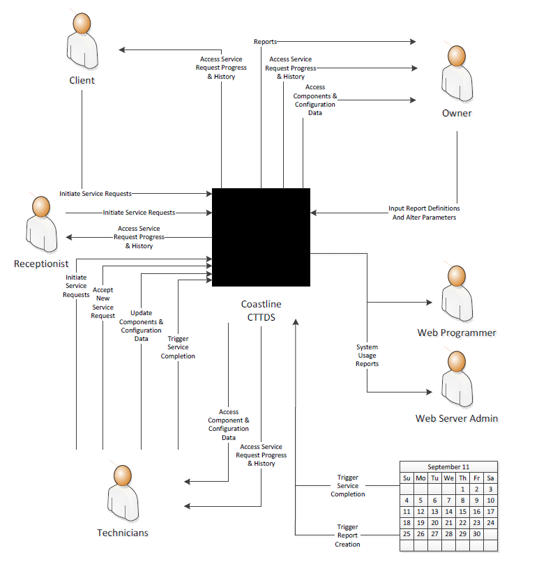
Systems Analysis Use Case Model Diagram Visio 2010 ... Systems Analysis Physical Data Flow Diagram for Client Service Visio 2010
System Context Diagram Software
The Visio diagram can add needed context to the overall picture. ... Select the Visio custom visual that shows the existing diagram

Data Flow Diagram Visio Download Iamdamer
Tutorial: Create Context Diagram in Visio 2016. 5,267 views5.2K views. Oct 7, 2016. 20. Dislike. Share. Save. Ligent Tutorials.
Make Your Visio Diagram Accessible To People With Disabilities
Table 5. Table of Visio shapes that map to Process Designer objects for audit diagram shapes stencil; Visio Shape Designer Object; Tagged process: Submap step: Decision: General step: Tagged document: Attachment: I/O: Component step: Manual operation: General step: Terminator: TerminateBranch step: Manual file: General step: Display: Text ...

Paul Herber Dataflow Diagram Shapes For Microsoft Visio Lucidchart Pro Mydraw Smartdraw Omnigraffle Pro Libre Office Conceptdraw Pro
Diagram Online Owner U0026 39 S Manual Wiring Diagram 2000 Isuzu Rodeo Cooling System Diagram Wiring Schematic , General Electricmercial Washer Wiring ...

Tutorial Creating A Context Diagram With Visio Youtube
... Case – A Case Tool with support for Data Flow Diagrams, UML, Entity Relationship Diagrams. ... Covers context diagram and level 1 diagram.
Solved In Visio Using Software And Batabase Data Flow Model Chegg Com
A context diagram "is the highest level in a Data-flow Diagram (DFD) showing the relationship between a system and other external entities." The external entities can be external data stores, organizations, systems, etc. Every context diagram must have a context bubble, which is first drawn in the center of the chart.

Creating An Information System Data Flow Diagram Information Security University Of Florida
Visio-Context Diagram.vsd Author: mikef Created Date: 3/5/2010 3:13:19 PM ...
Visio
Step 2: Click on Open Libraries and select the appropriate category. It is advisable to use the templates in System Context Diagram Templates to get a picture of what you need to draw. Step 3: Next, drag the correct shapes and drop them onto the canvas to create the context diagram. To write into the form, double click on it.

7 Useful Methods To Create Uml Sequence Diagram Online
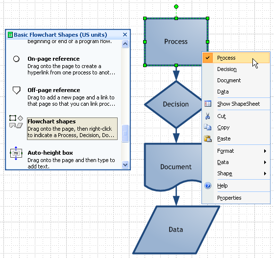
Hint: a Context Diagram is a simplified version of the Data Flow Diagram invented by Larry Constantine in the 1970s (see separate article). This shape represents a Process, which in the context (no pun intended) of a Context Diagram means the whole of the proposed system. The process should be treated as a 'black box', the internal details ...
Data Flow Diagram Software For Mac
12+ Context Diagram Visio.Microsoft visio is a software application that allows users to create diagrams with vector images. System context diagrams can be helpful in understanding the context which the system will be part once the diagram is more concrete, it may become an artifact using visio or some other tool which.

Data Flow Diagram Software For Mac
To create new DFD, select Diagram > New from the toolbar. In the New Diagram window, select Data Flow Diagram and click Next. Enter Context as diagram name and click OK to confirm. We'll now draw the first process. From the Diagram Toolbar, drag Process onto the diagram. Name the new process System.

Adding Structure To Your Diagrams In Microsoft Visio 2013 Microsoft Press Store
Draw Context Diagram Using Visio Written By Dominquez Busell Tuesday, November 16, 2021 Add Comment Edit. 1. How to Create a Block Diagram in Visio . Block diagrams play several significant roles. They can be of great assistance whenever a clear image of a system or control flow is needed. These blocks illustrations make it easier for software ...
Context Diagram Software Lucidchart
Diagram Wiring Honeywell 7500 Thermostat No Heat Wiring Diagram 1966 Pontiac Wiring Diagrams , Microsoft Visio Context Diagram , Wiring Diagram For ...
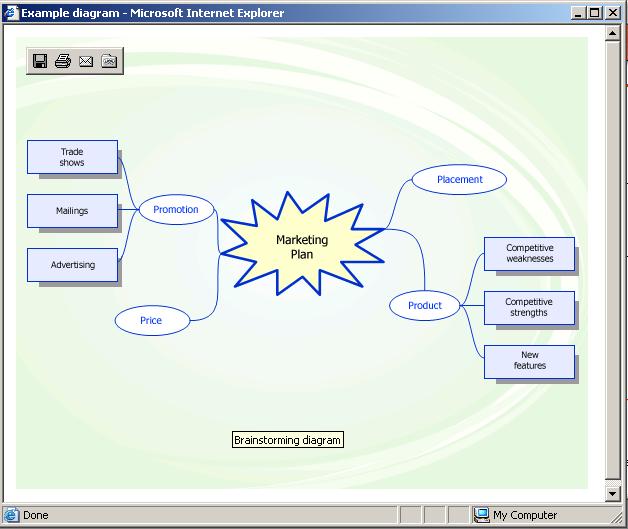
What S The Difference Between A Cause And Effect Diagram And A Workflow Diagram What S A Brainstorming Diagram Anyway Mai Lan S Visio Blog

What Is A Workflow Diagram And Who Uses Them Monday Com Blog
Caseagile Business Process Management And Enterprise Architecture Enterprise Composer For Visio 2016
Beth Shearon Web Portfolio Systems Analysis Diagrams Page
Context Level Data Flow Diagram Mechanical Engineering

How To Simplify Flow Charting Cross Functional Flowchart In Searching Of Alternative To Ms Visio For Mac And Pc With Conceptdraw Diagram Idef0 Visio Data Flow Visio

Introduction To Context Diagrams Business Analyst Community Resources Modern Analyst
Context Diagram Template Creately
Visio Multi Shapes Visio Guy
Data Flow Templates Editable Online Or Download For Free Creately
Dia Sheet Gane And Sarson Gane And Sarson Dfd
Create A Data Flow Diagram In Visio
What Is Data Flow Diagram Dfd How To Draw Dfd
Comments
Post a Comment