41 erd vs class diagram
The main difference between UML and ERD is that UML is a modeling language that represents a system or a software visually while ERD is a diagram that represents the entities and their relationships in a database.. UML is a standard modeling language that helps to get a pictorial understanding of the software. There are various diagrams in UML such as class, object, use case, activity and many ... Use case diagrams can be described by mentioning who will perform what function, and which kind of association is exist between functions (use cases) and Class diagrams can be described by showing the system's classes, their attributes, functions, and the relationships among objects.
ERD vs Class Diagram Class Diagram This term is used in the software field. In one of the languages of software called "UML" or "Unified Modeling Language," there are structure diagrams which describe or show the structure of any system by the help of showing the classes of the system. These diagrams also show the operations of the classes, attributes, and relationships between ...

Erd vs class diagram
Data modeling is a technique to document a software system using entity relationship diagrams (ER Diagram) which is a representation of the data structures in a table for a company's database. It is a very powerful expression of the company's business requirements. Data models are used for many purposes, from high-level conceptual models, logical to … Pertemuan 1 - Perbedaan ERD dan Class Diagram. ERD merupakan suatu model untuk menjelaskan hubungan antar data dalam basis data berdasarkan objek-objek dasar data yang memiliki hubungan antar relasi. Nah, perbedaan antara garis tebal dan garis tipis adalah untuk menunjukkan weak entity-nya. Class diagram merupakan diagram yang menunjukan adanya ... There are many ways to tell the difference between ERD and Class diagram. For instance, ERD, otherwise known as Entity Relationship Diagram, only portrays systemic features. On the other hand, Class Diagram displays the most vital sections of a system, the systemic and behavioural features.
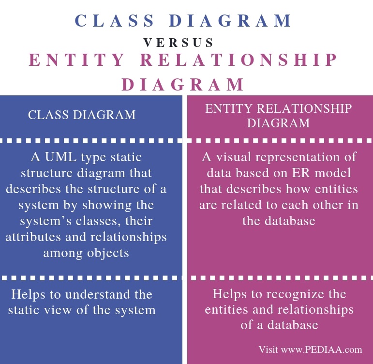
Erd vs class diagram. Data model may be represented in many forms, such as Entity Relationship Diagram or UML Class Diagram. Data Dictionary. Is a reference and description of each data element. It is a detailed definition and documentation of data model (learn more about data dictionary). The main difference between Class Diagram and Entity Relationship Diagram is that Class Diagram represents the classes and the associations among them in a software program while an Entity Relationship Diagram represents the entities and their relationships between them in a database.. UML (Unified Modeling Language) is a standard modeling language to visualize and document a software system. Systems Analysis and Design often require the conversion of a ERD (Entity Relationship Diagrams) to a Class Diagram. In this video learn how to change your d... ERD vs Class Diagram Diagram Kelas Istilah ini digunakan dalam bidang perangkat lunak. Dalam salah satu bahasa perangkat lunak yang disebut "UML" atau "Unified Modeling Language," ada diagram struktur yang menggambarkan atau menunjukkan struktur sistem apa pun dengan bantuan menunjukkan kelas-kelas sistem.
ER Diagram stands for Entity Relationship Diagram. 2. Definition: It is a general modelling language which is used to visualize the design of a software system. It is a pictorial representation of the real-world entities and their relationships with each other. 3. Relationship: It is the parent of ER diagram. It is the child of UML. 4. Use ER Diagram Uses. When documenting a system or process, looking at the system in multiple ways increases the understanding of that system. ERD diagrams are commonly used in conjunction with a data flow diagram to display the contents of a data store. They help us to visualize how data is connected in a general way, and are particularly useful for constructing a relational database. ER Diagram vs Class Diagram . ER (entity-relationship) diagrams and Class diagrams are two of the design diagrams that the software developers create usually during the design phases of the software engineering life cycle. ER diagrams are a product of entity-relationship modeling (ERM) technique for modeling databases. About the differences between class diagram and ERD, class diagram/model represent both structural and behavior features of a system (attribute and operations). Classes models act as a mold for the object instance. In class model, classes related to each other in association relationship, part-whole relationship and generalization relationship.
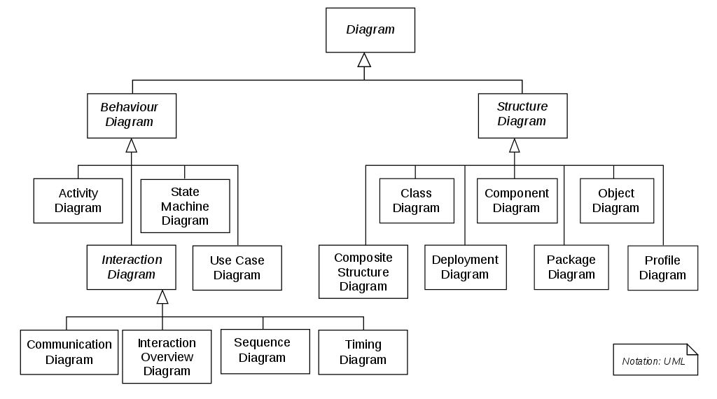
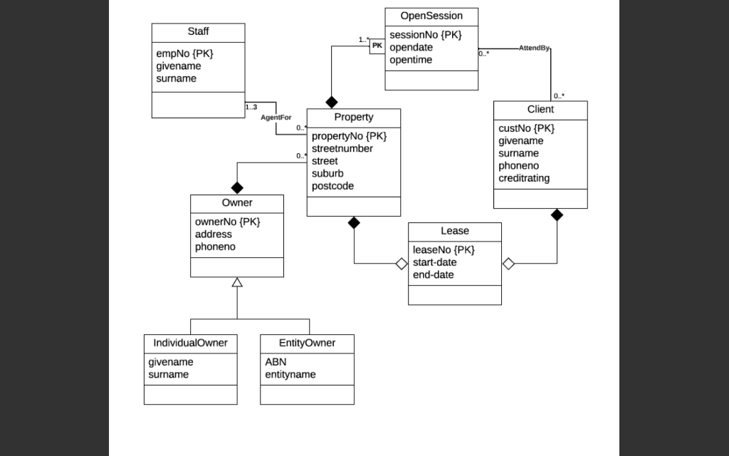
Entity Relationship Diagram, also known as ERD, ER Diagram or ER model, is a type of structural diagram for use in database design. An ERD contains different symbols and connectors that visualize two important information: The major entities within the system scope , and the inter-relationships among these entities . When it comes to system construction, a class diagram is the most widely used diagram. UML Class Diagrams is a type of static structure diagram that is used for general conceptual modeling of the systematics of the application. Such a diagram would illustrate the object-oriented view of a system. The object orientation of a system is indicated by a class diagram. What is ER Diagram? ER Diagram stands for Entity Relationship Diagram, also known as ERD is a diagram that displays the relationship of entity sets stored in a database. In other words, ER diagrams help to explain the logical structure of databases. ER diagrams are created based on three basic concepts: entities, attributes and relationships. Class vs Entity: The class diagram has a rectangular box with 3 sections that contains class, attribute and the operation name. The ER diagram has a rectangular box that contains the name of entity. The diagrams are shown in figure: Module (class name) Module code: int Module title: string Level: int
Purposes Of The Classes Uml Diagrams Readychef
Data modeling is a technique to document a software system using diagrams and symbols. It is used to represent communication of data. The highest level of abstraction for the data model is called the Entity Relationship Diagram (ERD). It is a graphical representation of data requirements for a database.

The Components Of A Class Diagram And How It Differs To Erd Stack Overflow
"Entity-relationship model" is just another name for the entity-relationship diagram. First coined in the 1970s by MIT professor Peter Chen, "entity-relationship model" was the original working title for the new diagram in his seminal paper "The Entity-Relationship Model: Toward a Unified View of Data."

Entity Relationship Diagrams Explained By Sonic The Hedgehog Dev Community
How to create ERD and Class diagram

Cs372 Entity Relationship Models
Entity-Relationship (ER) Diagrams 29 STUDENT DEPT MINOR_D FACULTY TUTORS CHAIR_F MAJOR_D Tutor Tutee 1 1 N M N M All departments have a faculty member who serves as the chair. A faculty member can only chair one department. N 1
Data Modelling With Uml Training Material
The Synchronize form Entity Relationship Diagram to Class Diagram dialog will be shown. The entity relationship diagrams in your project show on the left hand side of the table and the target class diagram shows on the right hand side. Click on the entity relationship diagram cell and the preview will be shown up.
What Is The Difference Between Uml And Erd Pediaa Com
UML is a common notation/language for object oriented modeling and it includes a multitude of diagram types. ERD is a diagram for data modeling (attributes and relationships). Some structural UML diagrams are fairly similar in what you can model, but the concept is different. Show activity on this post.

Class Diagram Staruml Documentation
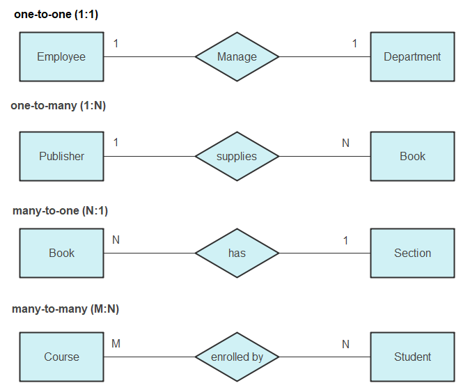
ERD means the Entity-relationship Diagram, reflecting the key relationships between different entities in an information system: members, roles, items, products, locations, concepts, and more. The most common practical uses of ERD include relational databases in software engineering, academic institutions, etc. Below is a good example of the ...
How Would You Create A Domain Model Class Diagram Chegg Com
Class diagrams are equivalent of ERDs in relational world and are mostly used to design classes in object-oriented programming languages (such as Java or C#). In class diagrams architects define: Classes (equivalent of entity in relational world), Attributes of a class (same as in an ERD) including data type,

Diagrams Pycharm
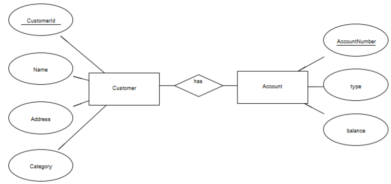
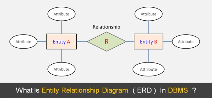
An Entity Relationship Diagram (ERD) is a visual representation of different entities within a system and how they relate to each other. For example, the elements writer, novel, and a consumer may be described using ER diagrams the following way:

Data Modeling Entity Relationship Diagram Er Diagram Business Analyst Community Resources Modern Analyst
1 Class Diagrams and Entity Relationship Diagrams (ERD) Class diagrams and ERDs both model the structure of a system. Class diagrams represent the dynamic aspects of a system: both the structural and behavioural features. ERDs, depicting only structural features provide a static view of the system. 2 Class Diagrams

Uml 2 Class Diagrams An Agile Introduction
There are many ways to tell the difference between ERD and Class diagram. For instance, ERD, otherwise known as Entity Relationship Diagram, only portrays systemic features. On the other hand, Class Diagram displays the most vital sections of a system, the systemic and behavioural features.

Uml Class Diagrams Class Inheritance And Relationships Between Classes The Freecodecamp Forum
Pertemuan 1 - Perbedaan ERD dan Class Diagram. ERD merupakan suatu model untuk menjelaskan hubungan antar data dalam basis data berdasarkan objek-objek dasar data yang memiliki hubungan antar relasi. Nah, perbedaan antara garis tebal dan garis tipis adalah untuk menunjukkan weak entity-nya. Class diagram merupakan diagram yang menunjukan adanya ...

Difference Between Erd And Class Diagram Difference Between
Data modeling is a technique to document a software system using entity relationship diagrams (ER Diagram) which is a representation of the data structures in a table for a company's database. It is a very powerful expression of the company's business requirements. Data models are used for many purposes, from high-level conceptual models, logical to …

Difference Between Uml And Er Diagrams By Bhanu Priya Youtube

Class Diagram Template For Course Registration System Course Registration Erd 545x963 Png Download Pngkit
1

Convert Er Diagrams To Class Diagrams Astah
Er Diagram Symbols And Notations Edraw

Entity Relationship And Class Table Models In Pids A Entity Download Scientific Diagram
Entity Relationship Diagrams With Draw Io Draw Io
What Is The Difference Between Class Diagram And Entity Relationship Diagram Pediaa Com

Erd To Data Model Transformation Enterprise Architect User Guide
Class Diagrams Method Overloading Types Of Classes
Make Uml Diagrams Use Cases Use Case Diagram Erd Class Diagram And Etc By Saadabid12 Fiverr
Entity Relationship Diagrams With Draw Io Draw Io

Difference Between Class Diagram And Entity Relationship Diagram Varias Classes

How To Generate Class Diagram From Erd

Convert Uml To Er Models Astah

What Is An Entity Relationship Diagram And How To Make One Miroblog A Blog By Miro
1
Class Diagram Enterprise Architect User Guide

Make Erd Use Case Sequence Class Diagram For Your Sw Project By Abdo Hamdy Fiverr
Solved Question 4 Er To Relational Schema Mapping 6 Chegg Com

Data Modeling Entity Relationship Diagram Er Diagram Business Analyst Community Resources Modern Analyst
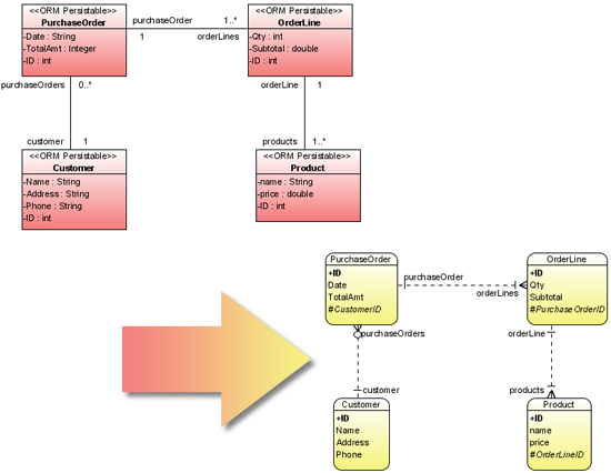
Er Diagram And Class Diagram Synchronization Object Relational Mapping Oo Software Modeling Tool
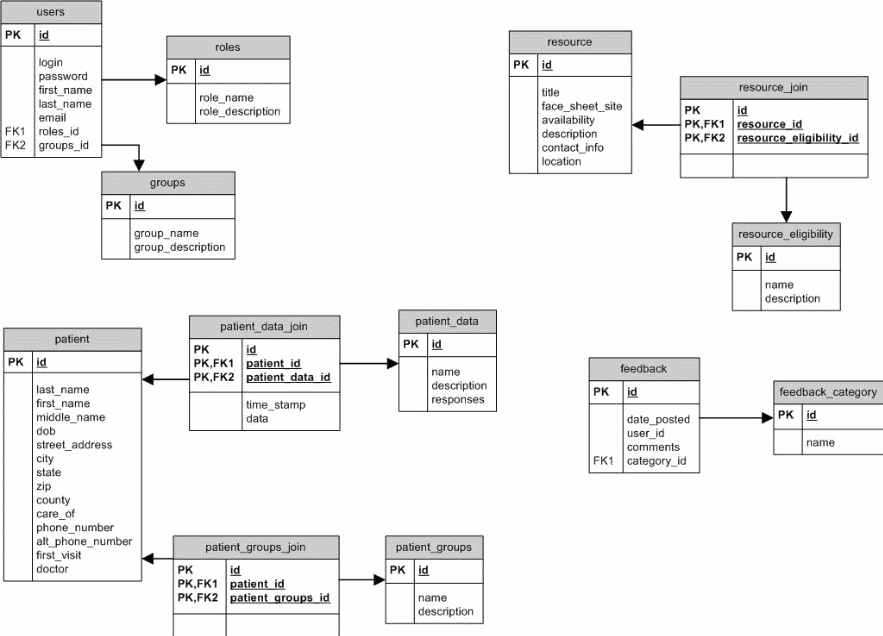
Is This An Entity Relationship Diagram Or A Class Diagram Stack Overflow
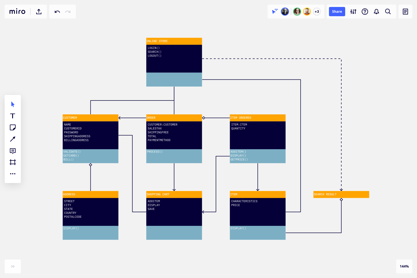
Uml Diagram Examples Types Miro
Information Models Main Events Receive Public Health Report Send Public Health Report Receive Acknowledgement Send Acknowledgement Entity Relationship Diagram Erd Data Structure This Establishes A Preliminary Organization Of The Defined Data

Entity Relationship Diagram Erd Er Diagram Tutorial
Do Classes In An Uml Class Diagram Always Translate To Entities In A Conceptual Data Model Stack Overflow
Entity Relationship Diagram Erd Explained Er Model In Dbms
Comments
Post a Comment