39 ladder diagram symbols
PLC Ladder Logic Diagram Symbols-III. May 3, 2020. by microdigisoft. 0. PLC programming with Function Block Diagram (FBD) -II. March 25, 2020. by microdigisoft 0. PLC Basic Input Devices and Sensors types. May 30, 2020. by ... Ladder Logic Schematic Symbol Flashcards. By John Rosz Terry Fleischman. This interactive object is designed to help learners memorize the schematic symbols used in ladder logic diagrams. Learners quiz themselves using electronic flashcards. Download Object.
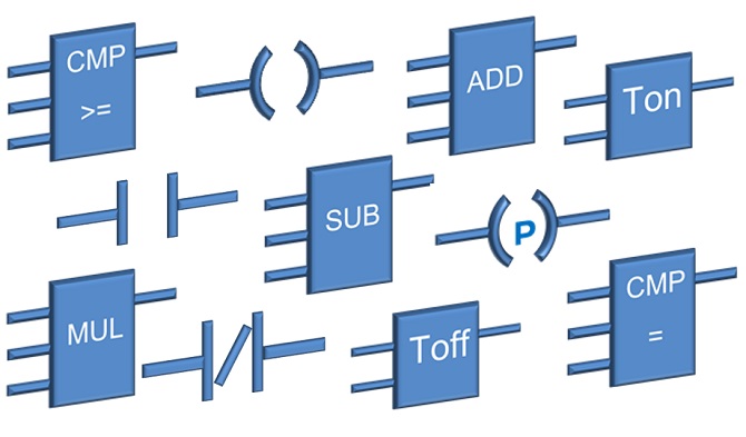
In last tutorial we have seen computational mathematical instructions Ladder Logic Symbols(PLC Ladder Diagram Symbols-II.This tutorial we will continue with "Timers" and "Counters" instructions.Timers are important part of PLC without which it is very difficult to think of executing a process.Timers are blocks that count the time as specified by the user and the executes the algorithm ...

Ladder diagram symbols
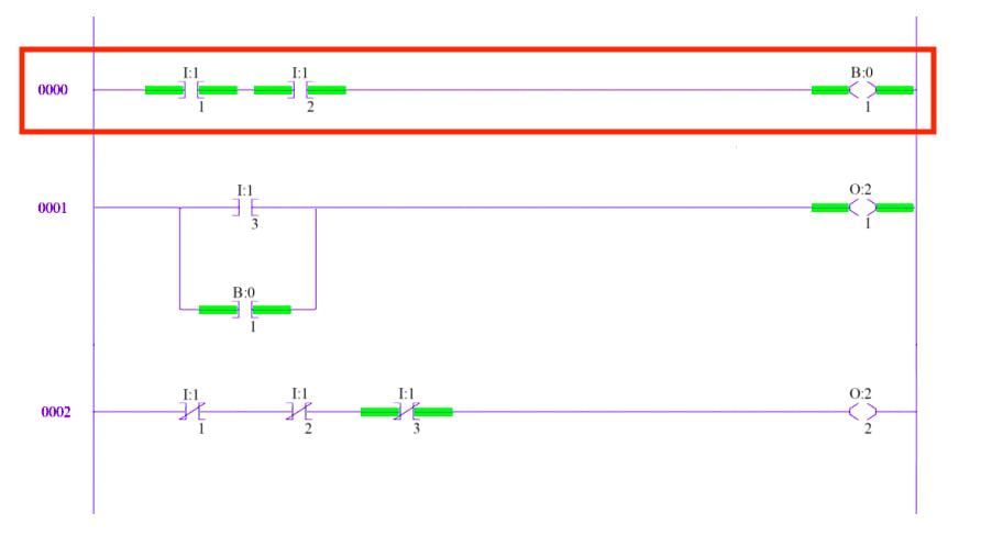
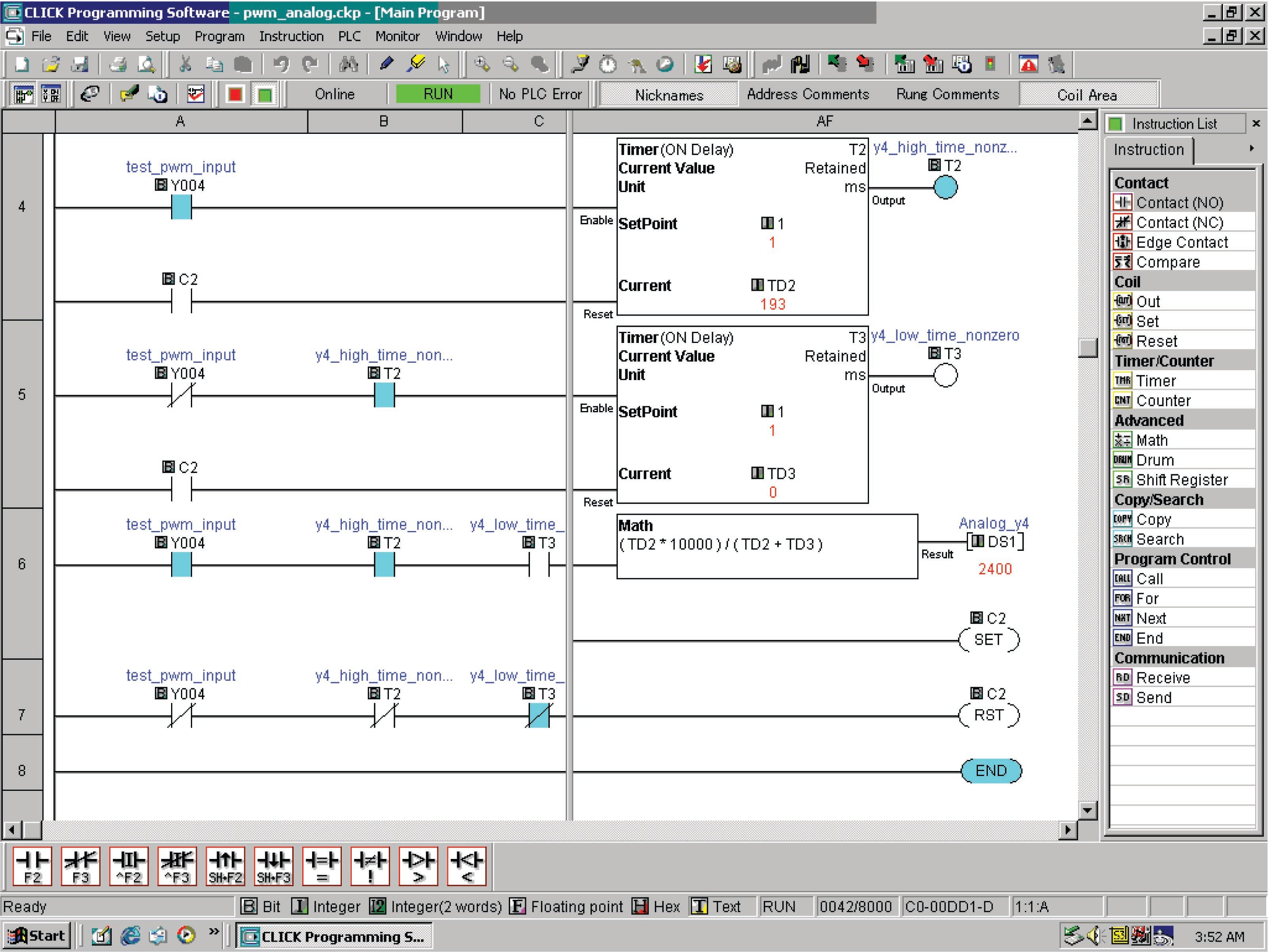
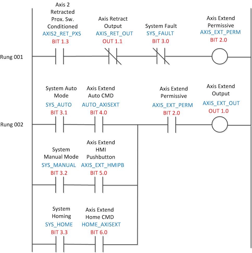
In ladder diagrams, the load device (lamp, relay coil, solenoid coil, etc.) is almost always drawn at the right-hand side of the rung. While it doesn't matter electrically where the relay coil is located within the rung, it does matter which end of the ladder's power supply is grounded, for reliable operation. Take for instance this circuit: Color-highlighting of Ladder Diagram components only works, of course, when the computer running the program editing software is connected to the PLC and the PLC is in the “run” mode (and the “show status” feature of the editing software is enabled). Otherwise, the Ladder Diagram is nothing more than black symbols on a white background. Ladder logic looks almost identical to a ladder diagram except the contacts and coils are replaced with computer bits. But we still need to illustrate what these bits represent, so we use logic symbols. These symbols come straight from relay logic diagrams even if some of the components are digital now.
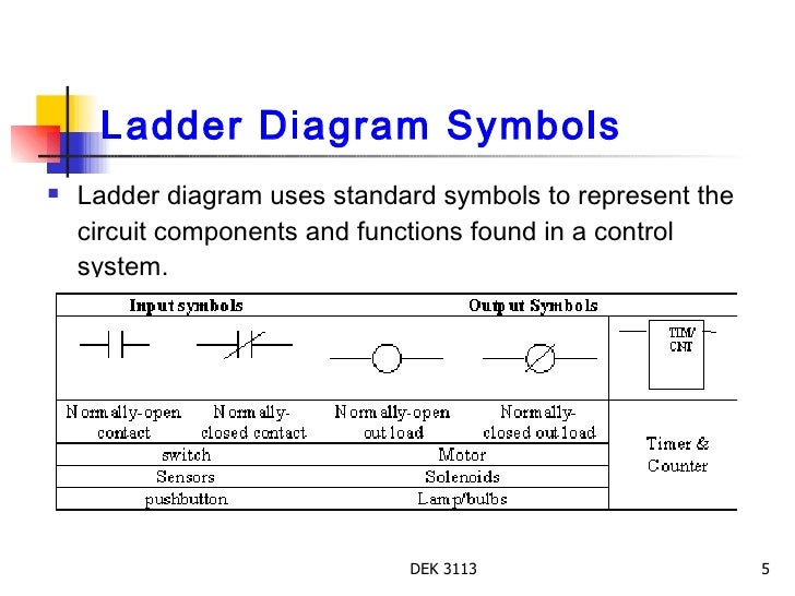
Ladder diagram symbols. Oct 2, 2018 - Ladder logic symbols are a set of symbols used in PLC ladder diagrams. Download all the IEC 61131-3 ladder diagram symbols as DWG, ... Line Diagrams A line (ladder) diagram is a diagram that shows the logic of an electrical circuit or system using standard symbols. A line diagram is used to show the relationship between circuits and their components but not the actual location of the components. Line diagrams provide a fast, easy understanding of the connections and ladder diagram or electrical schematic or elementary diagram can be divided into two distinct portions. The first is the power portion and the second is the control. ... Symbols used in Electrical Diagrams . Ch 2 Ladder Basics 3 Ladder circuits have some common characteristics. They are: 1. Power bar on the far left 2. Current flow from the ... Ansi architectural symbols receptacle and plug configurations circuit wiring diagrams mcgraw hill education access engineering smartdraw on twitter in schematics are covered by a variety of national international standards iec ieee here just few common electrical diagram schematic symbolstoyota drawings control real english typical drawing conventions symbol library for your form solidworks ...
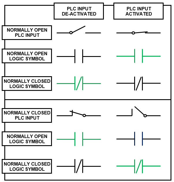
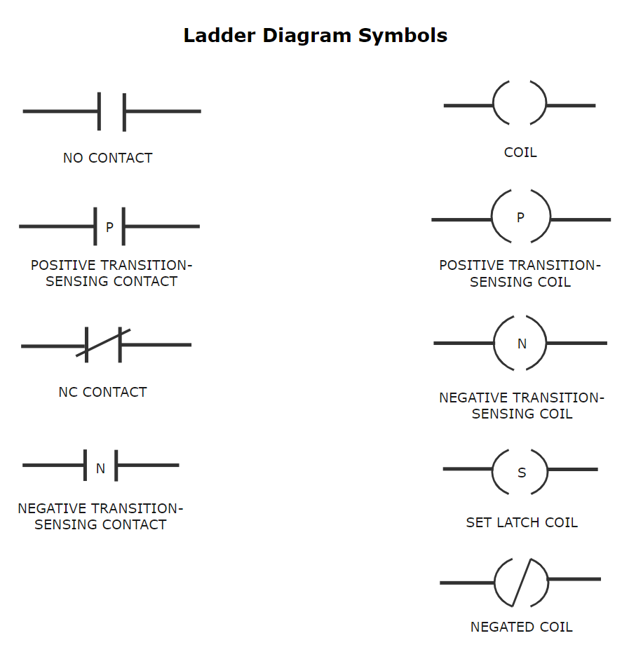
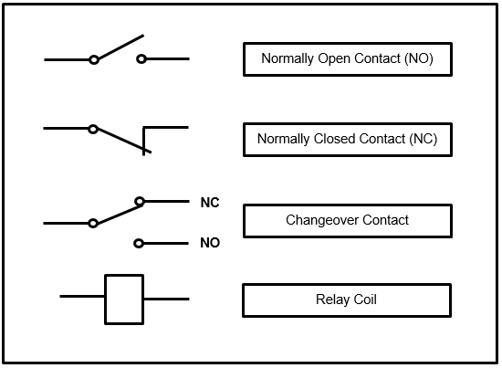
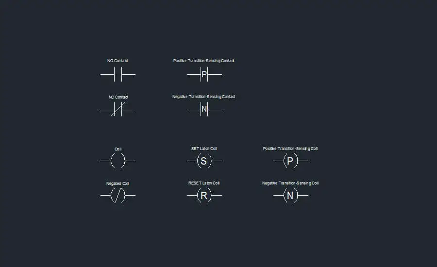
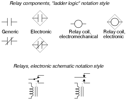
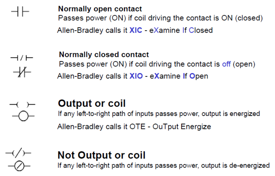
Feb 09, 2015 · Ladder logic was designed to have the same look and feel as electrical ladder diagrams, but with ladder logic, the physical contacts and coils are replaced with memory bits. Let’s take a look. For this program, the relay logic’s ladder diagram is duplicated with ladder logic; no more hard-wired logic, but memory locations instead. Jun 28, 2015 · The ladder diagram graphical programming language is standardized by the PLCopen organization, and thereby the symbols used in ladder diagrams.Since ladder logic is a graphical programming language, the PLC programs written in ladder logic are a combination of ladder logic symbols. Nov 30, 2015 · In drawing a ladder diagram, certain seven conventions are adopted: Convention 1 // The vertical lines of the diagram represent the power rails between which circuits are connected. The power flow is taken to be from the left-hand vertical across a rung. Convention 2 // Each rung on the ladder defines one operation in the control process. In ladder logic the normally open contact (NO) and normally closed contact (NC) symbols are mainly used to define PLC digital inputs and internal logic instructions. They have been translated into ladder logic from switches and relay contacts used in electric circuits. An coil in ladder logic is the symbol which mainly defines PLC digital outputs.
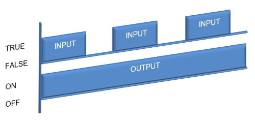
Ladder diagrams (sometimes called "ladder logic") are a type of electrical notation and symbology frequently used to illustrate how electromechanical switches and relays are interconnected. The two vertical lines are called "rails" and attach to opposite poles of a power supply, usually 120 volts AC. Ladder logic looks almost identical to a ladder diagram except the contacts and coils are replaced with computer bits. But we still need to illustrate what these bits represent, so we use logic symbols. These symbols come straight from relay logic diagrams even if some of the components are digital now. A ladder diagram, shown in figure 3, is a diagram that explains the logic of the electrical circuit or system using standard NEMA or IEC symbols. A ladder diagram is used to point out relationships between circuit components, not the actual location of the components. Ladder diagrams provide a fast and easy understanding of the connection of ... Apr 25, 2020 — The five most used ladder logic symbols are as follows: Normally Open Contact, Normally Closed Contact, Output Energize, Output Latch and Output ...What are the Ladder Logic S...Normally Open (NO) Contact ...Normally Closed (NC) Contac...1 of 3Ladder Logic is one of the most common PLC programming languages. The standards of the language are well documented by the International Electromechanical Commission (IEC) in the exhibit 61131-3. Howe...Continue on www.solisplc.com »2 of 3The most fundamental symbol of ladder logic programming is the Normally Open Contact or the Examine If Closed XIC Instruction. This symbol was created as a direct reapplication of the relay-based cont...Continue on www.solisplc.com »3 of 3The opposite of the Normally Open Contact is the Normally Closed. This validation will look at the specified bit and evaluate to TRUE when the bit is de-energized and FALSE when it's energized. The ap...Continue on www.solisplc.com »
Ladder Logic Symbols All Plc Diagram Symbols
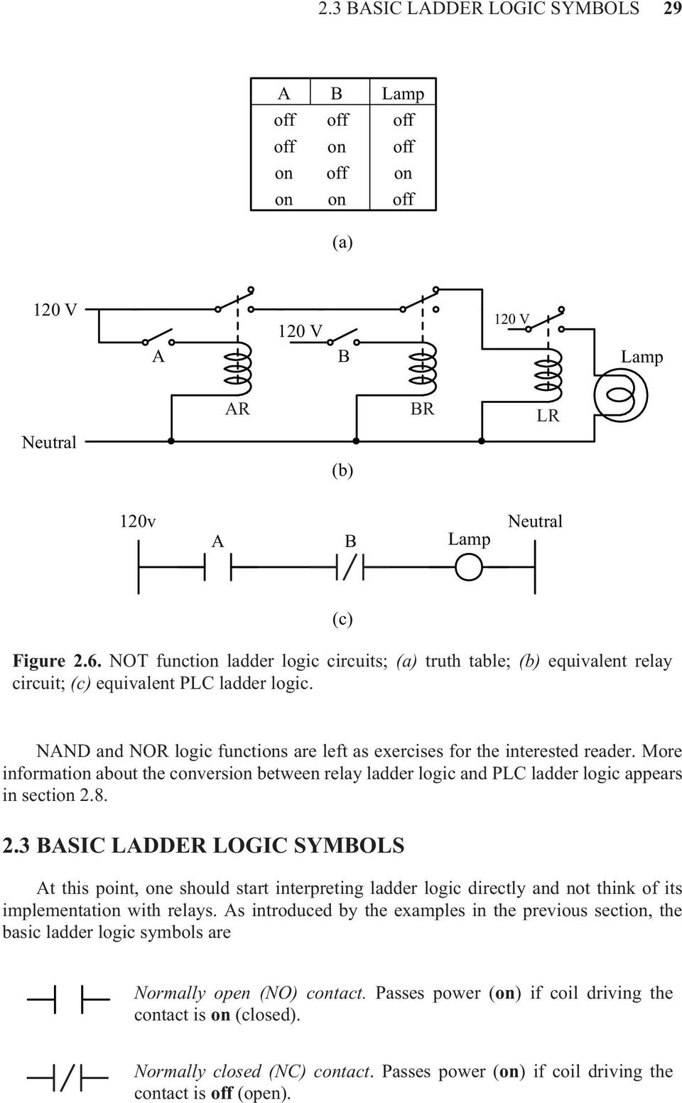
2Basic Ladder Logic Programming Chapter Topics: † Basic ladder logic symbols † Ladder logic diagram † Ladder logic evaluation † Start/stop logic OBJECTIVES Upon completion of this chapter, you will be able to: † Understand basic ladder logic symbols † Write ladder logic for simple applications Scenario: A program with a long scan time may not detect short-duration events.
Ladder Logic Programming Examples Ladder Logic World
These graphic symbols are the ones used most often on ladder diagrams for fluid power electrical control circuits. They are standard JIC (Joint Industrial Council) symbols as approved and adopted by the NMTBA (National Machine Tool Builders Association). They have been extracted from the Appendix of the NMTBA Specification EGPl-1967.

Ladder Logic Wikipedia
Ladder diagrams are advanced schematics widely used to record logic structures for industrial controls. These are called ladder diagrams because they mimic a ...1. What Is a Ladder Diagram?2. Application Scenarios of...3. Benefits of Using a Ladd...1 of 3Ladder diagrams are advanced schematics widely used to record logic structures for industrial controls. These are called ladder diagrams because they mimic a ladder, with two vertical rails (supply po...Continue on www.edrawmax.com »2 of 3Every system in the relay rack will be depicted with a symbol on the diagram of the ladder indicating the relations between such devices. Furthermore, other things beyond the relay rack, such as pumps...Continue on www.edrawmax.com »3 of 3Intuitive and self-documenting. A ladder diagram provides superb schematic interpretation focused on well-understood principles of circuit architecture. The learning curve to get going with a ladder d...Continue on www.edrawmax.com »

Ladder Logic Tutorial Part 2 Building Logic Plc Academy
Sep 04, 2017 · These graphic elements are called symbols. One of the smart things about the ladder logic symbols is that they are made to look like electrical symbols. Ladder logic was originally created for technicians, electricians, and people with an electrical background. People who are used to look at electrical diagrams and schematics.
3
ladder diagram symbols_text.pdf download. download 6 files . SINGLE PAGE PROCESSED JP2 ZIP . Uplevel BACK 952.6K . ladder diagram definition_jp2.zip download. 1.2M . ladder diagram examples_jp2.zip download. 777.2K ...
1
Basics 6 7.2 kV 3-Line Diagram : Basics 7 4.16 kV 3-Line Diagram : Basics 8 AOV Elementary & Block Diagram : Basics 9 4.16 kV Pump Schematic : Basics 10 480 V Pump Schematic : Basics 11 MOV Schematic (with Block included) Basics 12 12-/208 VAC Panel Diagram : Basics 13 Valve Limit Switch Legend : Basics 14 AOV Schematic (with Block included)

Figure 8 1 Process And Controller Ppt Download
Ladder Diagram symbols 10 TM240 - Ladder Diagram (LD) 4 LADDER DIAGRAM SYMBOLS 4.1 ContactsContacts with various functions are available. They can be added to the left side of the ladder diagram and connected to other contacts. They cannot be added to the far right, however, since this area is reserved for coils.
What Is A Ladder Logic And What Is Ladder Logic Diagram In Plc Plc Programmable Logic Controllers Industrial Automation Plc Programming Scada Pid Control System
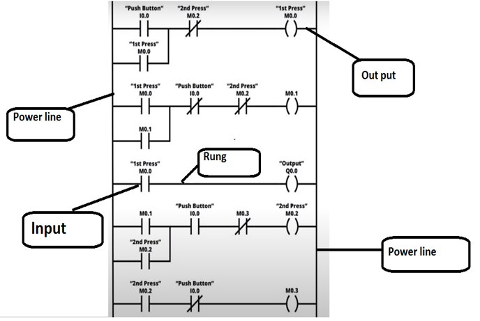
A ladder diagram comprises 'rails' that are two parallel lines drawn vertically and represent power supply, and 'rungs' that are several lines drawn horizontally with various symbols to connect the 'rails' to form an illustration of a control circuit. With that information, in a nutshell, a ladder diagram, as mentioned earlier, is a drawing of the logical structures of industrial ...

Symbols Used In Plc Programming Ladder Logic Diagram Symbols How To Interpret Plc Symbols Youtube
An actual ladder diagram of a relay-based motor control system is shown here, complete with red-line edits showing modifications to the circuit made by an industrial electrician: Perhaps the most confusing aspect of relay control circuits for students to grasp is the meaning of normal as it applies to the status of relay contacts.
2 Basic Ladder Logic Programming Pdf Free Download
An electronic symbol is a pictogram used to represent various electrical and electronic devices or functions, such as wires, batteries, resistors, and transistors, in a schematic diagram of an electrical or electronic circuit.These symbols are largely standardized internationally today, but may vary from country to country, or engineering discipline, based on traditional conventions.
Ladder Logic 201 Inputs Automationprimer
plc ladder diagram symbols Ladder Logic Symbols - Operation and Common Uses. March 2, 2021 February 28, 2021 by Steven. The ladder logic symbols that are used in PLC programming have been derived from traditional relay logic control circuits. If you have a basic knowledge of electric circuits then getting started in ladder logic programming ...
1
Ladder Logic Diagram Example 1 Computer Aided Manufacturing TECH 4/53350 27 Task: Draw a ladder diagram that will cause the output, pilot light PL2, to be on when selector switch SS2 is closed, push button PB4 is closed and limit switch LS3 is open. (Note: no I/O addresses yet.) Thought Process
Thevenin Equivalent Circuit Example Edrawmax Editable Templates
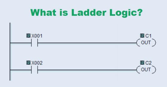
Nov 13, 2019 · No need to memorize all the standard symbols for each separate device. Parts of a ladder logic diagram and how it works PLC Programming: Ladder Logic Diagram (Photo from PLCacademy) The ladder logic diagram consists of two fundamental parts, which you can see as the vertical and the horizontal lines.
Chapter 2 Ladder
Mar 18, 2019 · 1. Just like on the diagram, we start with the stop push-button. It will be represented with an examine OFF bit. These look like a normally closed (NC) contact. Drag it to the first ladder rung and the program will place it to the far left. This will be a “Stop push button”. 2. Next, drag an examine ON bit and drop it to the right of the ...
Ladder Logic In Programmable Logic Controllers Plcs Technical Articles
Complex ladder diagram logic is the realization of simple logic. Therefore, mastering the basic ladder diagram is the key, No matter how complex the ladder diagram is, it is an organic combination of basic ladder diagrams. The following describes the explanation of Mitsubishi PLC ladder diagram symbols. Different PLC symbols represent different.
Ladder Logic Basics Ladder Logic Tutorial With Ladder Logic Symbols Diagrams Basic Plc Programming Paperback Politics And Prose Bookstore
Electrical Ladder Drawing Basics. Feb. 1, 2006. Understanding the basic layout, symbols, and cross-reference system of ladder diagrams will help you become a better troubleshooter. Roger Zieg.
Ladder Logic Symbols Ladder Logic World
Hubble diagram. Hubble's law can be easily depicted in a "Hubble diagram" in which the velocity (assumed approximately proportional to the redshift) of an object is plotted with respect to its distance from the observer. A straight line of positive slope on this diagram is the visual depiction of Hubble's law.

A Logical Guide To Relay Ladder Logic Symbols C3controls
The ladder diagram (LD) is a simple logic construction and more reliable than an electronic circuit controller. Easy to learn and read the program. Every programming symbol performs specific actions.

Electro Magnetic World Basic Ladder Logic Symbols
common is the ladder diagram, so called because it looks like the symbols that are used to represent the components in the system have been placed on the rungs of a ladder. From this point forward, ladder dia-grams will be referred to as "schematic" diagrams, or simply "schematics." A typical schematic of a pack-
Relay Logic Vs Ladder Logic Ladder Logic World
Ladder logic looks almost identical to a ladder diagram except the contacts and coils are replaced with computer bits. But we still need to illustrate what these bits represent, so we use logic symbols. These symbols come straight from relay logic diagrams even if some of the components are digital now.
Ladder Logic Tutorial With Ladder Logic Symbols Diagrams
Color-highlighting of Ladder Diagram components only works, of course, when the computer running the program editing software is connected to the PLC and the PLC is in the “run” mode (and the “show status” feature of the editing software is enabled). Otherwise, the Ladder Diagram is nothing more than black symbols on a white background.
Ladder Diagram Schematic Diagram Wiring Diagram Electrical Academia
In ladder diagrams, the load device (lamp, relay coil, solenoid coil, etc.) is almost always drawn at the right-hand side of the rung. While it doesn't matter electrically where the relay coil is located within the rung, it does matter which end of the ladder's power supply is grounded, for reliable operation. Take for instance this circuit:
Ladder Logic Symbols Ladder Logic World
Ladder Logic Symbols All Plc Diagram Symbols
Ladder Diagram Ld Programming Basics Of Programmable Logic Controllers Plcs Automation Textbook
Engineer On A Disk
Ladder Logic 202 Outputs Automationprimer

What Is The Difference Between Ladder Logic Function Block Diagrams Realpars

What Is Ladder Logic Ladder Logic Diagram Examples

Ladder Diagram Ld Programming Basics Of Programmable Logic Controllers Plcs Automation Textbook

Ladder Logic Symbols Function Graduate From Kurinjipadi Facebook
Ee Sharif Edu
Appendix C Circuit Schematic Symbols Applied Industrial Electricity

Ladder Logic Symbols Plc Programming In Rslogix 5000 Studio Allen Bradley
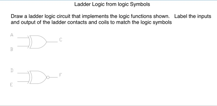
Solved Ladder Logic From Logic Symbols Draw A Ladder Logic Chegg Com

Electrical Ladder Drawing Basics Ec M
Ladder Logic Tutorial With Ladder Logic Symbols Diagrams
Plc Ladder Logic Symbols Plc Instrumentation Forum

Logic Gates Using Plc Ladder Important For Basic Programming
Comments
Post a Comment